Chiller Installation and Startup - 2021 BROAD Chiller Service Webinar Series 5# - BROAD U.S.A - BROAD USA INC.
←
→
Page content transcription
If your browser does not render page correctly, please read the page content below
2021 BROAD Chiller Service Webinar Series 5#

Chiller Installation and Startup

                BROAD U.S.A.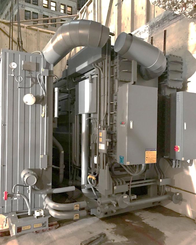
Chiller Installation and Startup

1. Mechanical room design
2. Chiller delivery inspection
3. Rigging and Installation
4. Wiring and control
5. Startup requirement
Mechanical room design
Mechanical room design
 ❑Temperature 41-109ºF, humidity
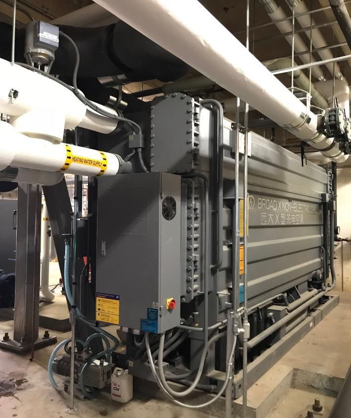
Shipping
❑ Double stager Chillers < BZ75 (gas fire 250 tons), BS100 (Steam fire 300 tons)(Max. width < 83inch)
  in single piece. Other units will be in 2-6 pieces shipment.

❑ If limited by site space or machine room access, small unit can also be split shipment (or split with
  steel frame),or steel-joint split shipment
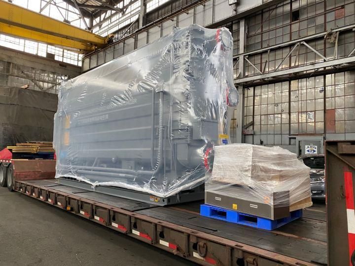
Shipping
❑ Lithium bromide solution is charged into the chiller when a
  unit is shipped in one piece

❑ Lithium bromide solution packed separately for split
  shipment chiller or single-piece shipment with unit shipping
  weight over 70 klbs.

Shipping container
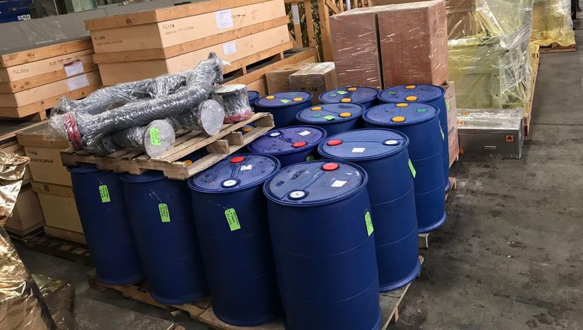
Delivery

After the chiller and spare parts are delivered to the jobsite, check the packing list to confirm the
following:

   ❑ If the chiller is in good condition outwardly

   ❑ The total parts and quantity

   ❑ Compound gauge readings

   ❑ Vibration meter sealing is still secure.
Packing list

                                                                         Lithium bromide solution
               Figure 6 Touch Screen Cabinet
           Touch Screen Cabinet is in cardboard box   Touchscreen

               Tool box is stainless steel box               Tools box             Vacuum Pump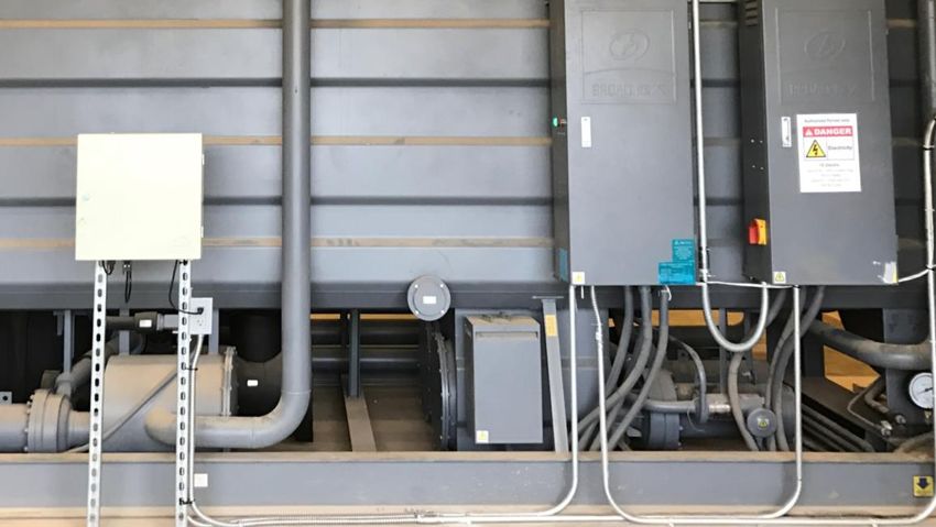
Compound gauge readings
   The proper shipping pressure range should be at around 3 +/- 1.5 Psi;

     Main Shell Gauge Location

      Generator Gauge Location
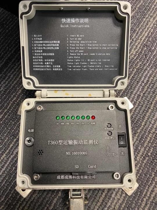
Vibration meter sealing

    To supervise the vibration during the transportation, each chiller is equipped with a vibration meter
    before shipment.
    Before unloading the chiller, the client and freight agent should check the vibration meter sealing.
    If the sealing is opened before checking, contact Broad for appropriate handling.
Storage
❑ Unit indoor storage is recommended to protect machine
elements;
❑ Don’t remove the intact protective component
transparency cover;
❑ Place unit in a good drainage area;
❑ Store loose parts box in a dry and secure place;
❑ Stored above freezing temperatures. (Chiller tested in
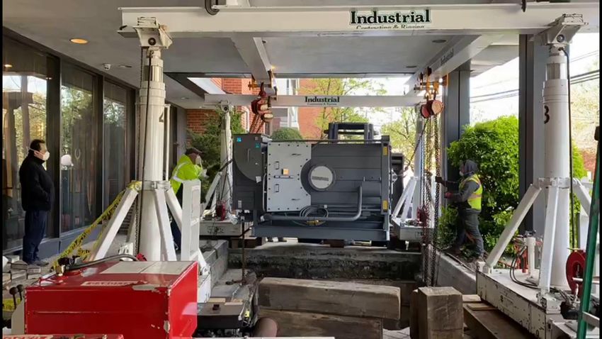
factory and refrigerant water may remained in unit)Rigging ❖ Rigging can only be handled by professionals
❑ Chiller’s shipping weight labeled on the nameplate.
❑ The pick-up points are the rigging lugs on the top of the chiller.
❑ The chiller must be kept level as much as possible when rigging. Because of Lithium bromide
solution in unit, The center of gravity maybe move when chiller not leveling.
center of
gravityMoving
❑ Only drag the dragging hole and do not place forces on other part of chiller.
❑ Both sides of generator and Main Shell must be lifted simultaneously
❑ Lift instead of dragging at an incline >10°.
❑ Lift must be leveled on the front and rear sides of roller dolly to prevent the chiller from
being twisted.
❑ Do make sure the foundation to be level, firm and not sinkable even for the temporary
location.Leveling
❑ After placing the chiller, leveling and lay thin steel plate where it is
uneven to guarantee compact contact between the chiller and
base.
❑ Take tube sheet as the leveling point and make front/rear and
left/right leveling, It should be leveled within 0.8/1000 both
lengthwise and sidewise within 2 hours.
Take a long enough clear
plastic Tubing with ¼ inch ID
dimension, fill in water fully
and discharge all the air out.
Follow the measurement steps
for each level measuring
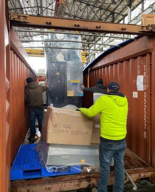
points.Chiller assembly ❑ Make sure the Main Shell matches the HTG when several units are delivered in split shipment, The Mark of chiller “1” and chiller ”2” can be found on the base beams. ❑ The weight of chiller must be evenly balanced. Otherwise, the chiller may be twisted slowly, which will finally result in damage or leakage. ❑ No access to the chiller or valves for unauthorized persons. Valves of the chiller are forbidden to be screwed. ❑ The chiller should be protected during installation. If chiller room is under construction, protective measures are needed to avoid damage or dirt to the chiller.
Chiller assembly

    ❑ Inform Broad immediately for chiller joining assistance when
      the split-shipped chiller is delivered on the jobsite.

    ❑ Prepare the tools and materials at the jobsite: Sets of
      welding and oxyacetylene cutting machine, High purity
      Nitrogen (99.999%) with regulator and gauge, 3 phase
       power, circulation fan.

    ❑ Purge and Leak check after assembly;

    ❑ Charge Lithium bromide solution to chiller when power
       and heat source are ready for chiller startup
Chiller assembly
Water System Installation

❑ The weight of all the external pipes should be
  taken by supports and rigging hooks, but never by
  the chiller, expansion Joint is recommended.

❑ Pressure gauge and thermometer should be set near the
  outlet/inlet of the external pipe for easy observation.
❑ The piping setup should easy for maintenance. and easy
  to open the water box cover.

❑ Common head water system, the motorize valve must
  be equipped at the chilled W. and cooling W. outlet
  of every chiller

❑ Cooling tower should be located far away from the heat
  and dust. Especially it should be 40’ (12m) far from the
  stack or the stack should be 6.5’ (2m) higher than cooling
  tower.
Water System Installation
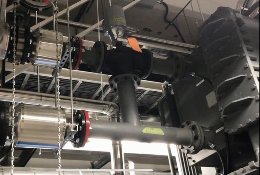
Chilled Water and cooling water drain hose must be removed before piping fill water for
cleaning, the hose used for draining the water out of the chiller tubes during shipment.
The hole must be plugged, or a shutoff valve can be installed.
Before Before After After
ORInstallation – Burner Any work on the burner or applicable interfaced product (controls) must be completed within the guidelines of the manufacturer’s instructions and applicable local and national codes.
Installation – Gas train
❑ To achieve better start conditions, the distance between burner and gas valves should be as
  small as possible. Observe gas train layout and flow direction.
❑ The gas train must be purged prior to first commissioning.
Exhaust System

❑ Unit exhaust pressure: 0 ~ 0.4 inch H2O (varies with load)

❑ Each chiller should be equipped with an intendent exhaust stack. If the
  shared exhaust stack must be applied, it should be insert type and the main
  stack should be larger and higher to avoid any interference with each other

❑ Wind shield, rain cover and lightening rod
  (refer to local requirement) should be
  installed at the outlet of the exhaust stack.

❑ Condensed water drain and fouling
  collector should be installed between chiller
  and stack to prevent condensate back to
  chiller.
Installation – Hot water valve

   All hot waterlines should be properly insulated to avoid heat loss to ambient.
Installation – Steam system
Chiller Wiring
Chiller Wiring

 ❑ The flexible conduit required to connect Control cabinet,
   the control cabinet may need to slightly move on service or
   maintenance.
 ❑ All wires must connect from the bottom of control cabinet,
   It’s prohibit to drill hole on the top the cabinet.

                              Ground connection
Touch Screen Installation ❑ Installed in chiller room, office or other places. It can be fixed on the desk or wall- mounted; should be convenient for observation and hearing the alarm. ❑ The wiring distance between control cabinet and touch screen is 100’ (30m) max for standard supply and could be 1640ft (500m) for special order. ❑ Single-phase/3-pole plug should be preserved within 3.2’ (1m) of the installation. 120V-60HZ- 1P Plug for touch screen must be single-phase, 3-pole (the third pole is for grounding).
Control sequence and wiring

❑ For the safety of the chiller and efficiency,
   Broad requests to be able to control the
   chilled water and cooling water flow on/off.
❑ Do not jump out safety devices (flow switches,
   pressure switches) or adjust the safety value of
   the device.
❑ Condenser water flow can NOT run alone
   without chilled water flow.
❑ Do not shut off chilled water system pump
   manually or close the valves to reduce chilled
   water flow when Broad chiller is online or in
   dilution off mode.
Chilled water and cooling water flow control

     Single chiller system or dedicated pumps system, chiller
     control the Chilled w. pump and Cooling w. pump.

     Multiple-chiller systems with manifolded pumps, should
     install the automatic two-position isolation valves at each
     chiller, chiller control the Chilled w. valve and Cooling w.
     valve. When turning on a chiller, a pump is turned on and
     the isolation valve is opened

     For chiller normal operation, must keep the minimum
     chilled water flow rate anytime
Internet monitoring A dedicated internet line is required, the RJ45 connection is to be dropped inside the control cabinet. Chiller can use either static or dynamic IP address. If static IP applies, IP address, subnet address, gateway address request, and open internet port 5700 for data transfer must be provided. Remote monitoring cannot access firewalls or VPN networks. Broad monitoring center data server IP 61.187.123.142. Broad center web server IP 61.187.123.138. If have multi-chiller, One RJ45 internet cable dropped inside control cabinet with have internet gateway and 5 conduit shield cable have to place to connect each chiller together for internal communication.
Building Automation System (BAS) Control Interface

  ❑ Dry contact of BAS Control Interface
   2 contacts for input:
   BAS start (ON), BAS shut off (OFF) , momentary signal with its duration 5 second.
   Caution: When BAS Start (On)/Shut Off(Off) is getting through at the same time, the chiller will
   take it for a chiller shut-off signal.
   4 contacts for output:
   Control mode ON: controlled by BAS control system OFF: controlled by chiller itself
   Chiller status ON: chiller is in operation (dilution included) OFF: chiller is shut off
   Dilution ON: chiller is in dilution process OFF: chiller is in non-dilution
   Fault ON: fault OFF: fault free

  ❑ Communication Interface

   the interface such as Modbus RTU, Modbus IP, BACnet MSTP,BACnet IP and Lonwork.
   If addition interface required, Please call Broad local office.
Building Automation System (BAS) Control Interface
New chiller installation and startup procedure

    ❑ Chiller delivery inspection

    ❑ Project installation kickoff meeting

    ❑ Chiller assembly or supervise

    ❑ Chiller Installation Check List (GC complete)

    ❑ Request for start-up of Broad Absorption Machine(s) Form (GC signed and send back two
      weeks before startup)

    ❑ Broad Tech on site startup (2~3 day each chiller)

    ❑ Chiller operation training and hand over
Q&A
BROAD U.S.A Inc - New Jersey BROAD U.S.A. Inc - California
401 Hackensack Ave, Suite 503 100 Citrus St, Suite 250
Hackensack, NJ 07601 West Covina, CA 91791
Tel: (201) 678-3010 Tel: 626-967-8651
Fax: (201) 678-3011 Fax: 626-967-8654
Sales@broadusa.com
Service@broadusa.comYou can also read