CBCT Electron Density & Image Quality Phantom System - USER GUIDE - CIRS
←
→
Page content transcription
If your browser does not render page correctly, please read the page content below
CBCT Electron Density &
Image Quality Phantom System
                                                                           Model 062M, 062MA & 062MQA

                                                                          USER GUIDE

     MINIMIZE DOSE • INCREASE IMAGE QUALITY • ENHANCE OUTCOMES

 900 Asbury Ave • Norfolk, Virginia 23513 • USA • Tel: 757-855-2765 • WWW.CIRSINC.COM

                                            1
OVERVIEW

        CBCT ELECTRON DENSITY & IMAGE QUALITY PHANTOM SYSTEM

The CBCT Electron Density & Image Quality Phantom System                                          data. The phantom can also accommodate any ion chamber
integrates three phantoms in one highly functional and ergo-                                      for dose measurements and validation of heterogeneity correc-
nomic package. The phantom system can be configured as:                                           tion based on the corrected CT calibration curve.
       Model 062M Electron Density Phantom                                                        Model 062MQA CBCT Electron Density & Image Quality
                                                                                                  Phantom configuration adds the Model 062QA-35 Im-
       Model 062MA CBCT Electron Density Phantom
                                                                                                  age Quality Phantom to the 062MA CBCT Electron Density
       Model 062QA-35 Image Quality Phantom                                                       Phantom configuration. The Image Quality Phantom presents
                                                                                                  a series of features designed to perform the entire set of Image
       Model 062MQA CBCT Electron Density and Image
                                                                                                  QA tests for Computed Tomography recommended in Report
       Quality Phantom
                                                                                                  #1 of the Task Group as approved by the American Association
The “M” within the model numbers stands for “modular” and                                         of Physicists in medicine. This phantom is also compliant with
is used to suggest that any of these phantoms can be used                                         TG-142 (Table VI) Report: QA of Medical Accelerators.
separately or in combination with extra parts to form a different
                                                                                                  The size of the 062MA and 062MQA covers geometries for
phantom.
                                                                                                  imager dimensions of up to 40 cm X 40 cm. They are made of
Model 062M Electron Density Phantom configuration is                                              Plastic Water®-LR (15 keV - 8 MeV) and contains a set of tissue
composed of Head and Body Electron Density sections and                                           equivalent electron density plugs for calibration. Additional inter-
tissue-equivalent electron density plugs.                                                         changeable slabs along with the phantom’s support system al-
                                                                                                  low for off axis repositioning of the Electron Density section and
Model 062MA CBCT Electron Density Phantom configura-
                                                                                                  CBCT Image Quality Phantom with an increment of 1.25 cm.
tion is an extended version of the CIRS Model 062M Electron
Density Phantom specially designed for Cone Beam kV and                                           While the design intent of the both the Model 062MA and
MV CT imaging systems. It was designed in collaboration with                                      062MQA is to account for the specific geometry of volumetric
Dr. Peter H. Cossmann, PhD to provide a reliable tool for CT                                      imaging equipment, these configurations are also suitable for
number to electron density calibration in volumetric imaging.                                     axial/helical CT equipment and provides the user with an imag-
Reliable CT electron density calibration curves help enable                                       ing volume that closely resembles an average male torso.
treatment plan adaptation directly from Cone Beam CT (CBCT)

REFERENCES:
PH Cossmann, A Stuessi, C von Briel, Characterisation of a Linac Cone-Beam-CT Option:             PH Cossmann, U. Gneveckow Characterisation of a Linac Cone-Beam-CT Option: What Is the
What Is the Future Potential for Treatment Planning? SU-GG-T-536, Medical Physics, Vol. 35,       Future Potential for Treatment Planning? Medical Physics (submitted).
No. 6, June 2008.
                                                                                                  PH Cossmann, V. Varchena A novel phantom design for the electron density calibration of a
PH Cossmann, U Gneveckow, C von Briel Characterisation of a Linac Cone-Beam-CT Option:            linac CBCT option, Zeitschrift fuer Medizinische Physik (submitted).
What Is the Future Potential for Treatment Planning? SSK17-04, RSNA Scientific Assembly and
Annual Meeting Program 2008, p. 546.                                                              ICRU Report No.44, January 1989, p.22.

                                                                                              2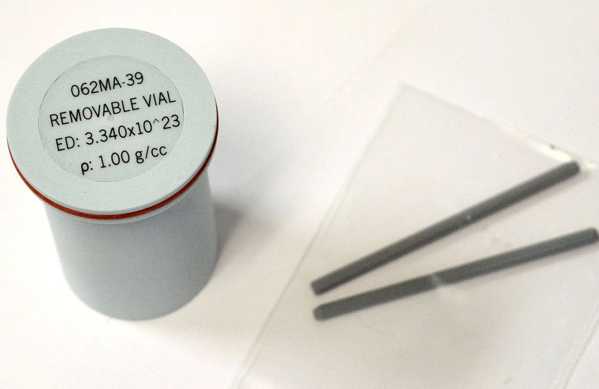
CBCT ELECTRON DENSITY & IMAGE QUALITY PHANTOM SYSTEM

      TABLE OF CONTENTS

CBCT ELECTRON DENSITY &                                                                                    DATA COLLECTION AND ANALYSIS
IMAGE QUALITY PHANTOM SYSTEM                                                                                CBCT Electron Density & Image Quality Phantom System
 Standard System Components .  .  .  .  .  .  .  .  .  .  .  .  .  .  .  .  .  .  .  . 4                    Model 062M, 062MA & 062MQA . . . . . . . . . . . . . . . . . . 17
 System Configurations .  .  .  .  .  .  .  .  .  .  .  .  .  .  .  .  .  .  .  .  .  .  .  . 5               Treatment Planning .  .  .  .  .  .  .  .  .  .  .  .  .  .  .  .  .  .  .  .  .  .  . 17
                                                                                                              Quality Assurance Testing .  .  .  .  .  .  .  .  .  .  .  .  .  .  .  .  .  .  .  . 17
OVERVIEW & SPECIFICATIONS                                                                                     Evaluation of Effective Energy in CT  .  .  .  .  .  .  .  .  .  .  .  .  .  . 18
 Electron Density Phantom Model 062M  .  .  .  .  .  .  .  .  .  .  .  .  .  .  . 6                         CBCT Electron Density & Image Quality Phantom
 CBCT Electron Density Phantom Model 062MA  .  .  .  .  .  .  .  .  .  .  . 7                               Model 062MQA .  .  .  .  .  .  .  .  .  .  .  .  .  .  .  .  .  .  .  .  .  .  .  .  .  . 19
 CBCT Image Quality Phantom Model 062QA-35  .  .  .  .  .  .  .  .  .  .  . 8                                 Image Quality Overview  .  .  .  .  .  .  .  .  .  .  .  .  .  .  .  .  .  .  .  . 19
 CBCT Electron Density & Image Quality Phantom                                                                Initial Phantom Set Up  .  .  .  .  .  .  .  .  .  .  .  .  .  .  .  .  .  .  .  .  . 19
 Model 062MQA .  .  .  .  .  .  .  .  .  .  .  .  .  .  .  .  .  .  .  .  .  .  .  .  .  . 10               CBCT Image Quality Phantom Model 062QA-35 .  .  .  .  .  .  .  .  .  . 20
 Optional Accessories Model 062M, 062MA & 062MQA . .  .  .  .  .  . 11                                        Uniformity  .  .  .  .  .  .  .  .  .  .  .  .  .  .  .  .  .  .  .  .  .  .  .  .  .  .  . 20
                                                                                                              CT Number Linearity .  .  .  .  .  .  .  .  .  .  .  .  .  .  .  .  .  .  .  .  .  . 20
                                                                                                              Contrast-to-Noise Ratio (CNR)  .  .  .  .  .  .  .  .  .  .  .  .  .  .  .  .  . 21
ASSEMBLY & SET UP                                                                                             Slice Thickness .  .  .  .  .  .  .  .  .  .  .  .  .  .  .  .  .  .  .  .  .  .  .  .  . 21
 CBCT Electron Density & Image Quality Phantom System                                                         Low Contrast Visibility  .  .  .  .  .  .  .  .  .  .  .  .  .  .  .  .  .  .  .  .  . 22
 Model 062MA & 062MQA  .  .  .  .  .  .  .  .  .  .  .  .  .  .  .  .  .  .  .  .  .              12
   Support Base Assembly .  .  .  .  .  .  .  .  .  .  .  .  .  .  .  .  .  .  .  .  .            12          Magnification/Spatial Linearity  .  .  .  .  .  .  .  .  .  .  .  .  .  .  .  .  .               22
   CBCT Section set up .  .  .  .  .  .  .  .  .  .  .  .  .  .  .  .  .  .  .  .  .  .           12          Spatial Resolution . .  .  .  .  .  .  .  .  .  .  .  .  .  .  .  .  .  .  .  .  .  .  .         23
   Positioning  .  .  .  .  .  .  .  .  .  .  .  .  .  .  .  .  .  .  .  .  .  .  .  .  .  .  .   13          Modulation Transfer Function (MTF) .  .  .  .  .  .  .  .  .  .  .  .  .  .  .                   23
 CBCT Electron Density & Image Quality Phantom                                                              CBCT Electron Density & Image Quality Phantom System
 Model 062MQA .  .  .  .  .  .  .  .  .  .  .  .  .  .  .  .  .  .  .  .  .  .  .  .  .  .        14        Model 062MA & 062MQA
   “In Air” Set up  .  .  .  .  .  .  .  .  .  .  .  .  .  .  .  .  .  .  .  .  .  .  .  .  .     14          Dosimetry Arrangement & Measurements .  .  .  .  .  .  .  .  .  .  .                             24
 CBCT Image Quality Phantom Model 062QA-35 .  .  .  .  .  .  .  .  .  .                           15          Electron Density Sample Test Data Sheet .  .  .  .  .  .  .  .  .  .  .  .                       25
   “In Air” Set up  .  .  .  .  .  .  .  .  .  .  .  .  .  .  .  .  .  .  .  .  .  .  .  .  .     15          Electron Density Test Data Sheet  .  .  .  .  .  .  .  .  .  .  .  .  .  .  .  .                 26
   “On the Couch” Set up  .  .  .  .  .  .  .  .  .  .  .  .  .  .  .  .  .  .  .  .  .           15        Handling Instructions  .  .  .  .  .  .  .  .  .  .  .  .  .  .  .  .  .  .  .  .  .  .  .         27
 Water-Fillable Electron Density Plug .  .  .  .  .  .  .  .  .  .  .  .  .  .  .  .              16        Warranty . .  .  .  .  .  .  .  .  .  .  .  .  .  .  .  .  .  .  .  .  .  .  .  .  .  .  .  .  .   27

                                                COMPUTERIZED IMAGING REFERENCE SYSTEMS, INC.
                                                               900 Asbury Ave • Norfolk, Virginia 23513 • USA
                                                                 Tel: 757.855.2765 • Fax: 757.857.052
                                                              Email: admin@cirsinc.com • www.cirsinc.com

                                                                                                       3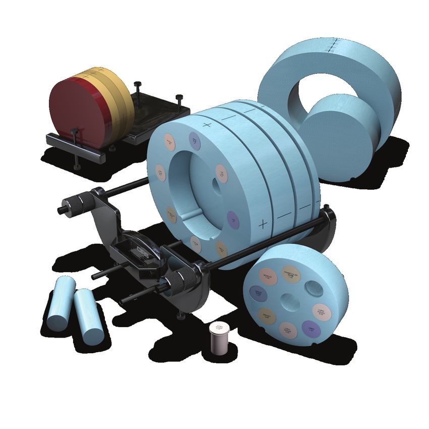
CBCT ELECTRON DENSITY & IMAGE QUALITY PHANTOM SYSTEM
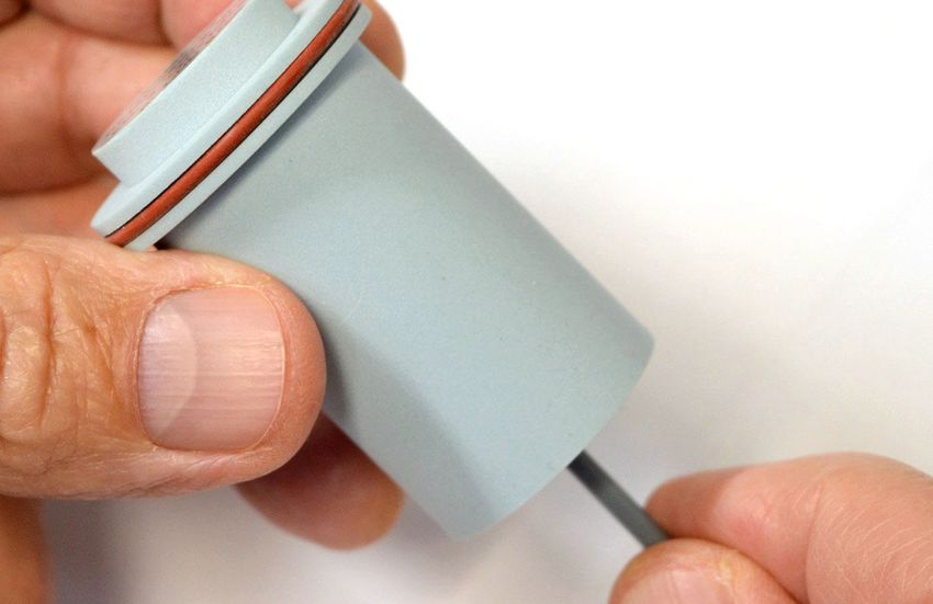
STANDARD SYSTEM COMPONENTS
Electron Density Phantom 062MA-01 Electron Density Phantom 062MA-02
1 2 3 Electron Density Phantom Plugs
Head Insert Body w/feet
CBCT Electron Density Phantom 062MA-37 CBCT Electron Density Phantom 062MA-36 CBCT Electron Density Phantom 062MA-33
4 5 6
Annulus Insert (100 mm thick) Annulus (100 mm thick) Bolus Section (12.5 mm thick)
CBCT Electron Density Phantom 062MA-34 CBCT Electron Density Phantom 062MA-24 9 Background Insert (2 Units) 062MA-32
7 8
Bolus Section (37.5 mm thick) Bolus Section (50 mm thick)
062MA & 062MQA 062MA-30 CT Image Quality Phantom 062MQA-50 CT Image Quality Phantom 062MQA-30
10 11 12
Holder & Stand Holder & Stand
4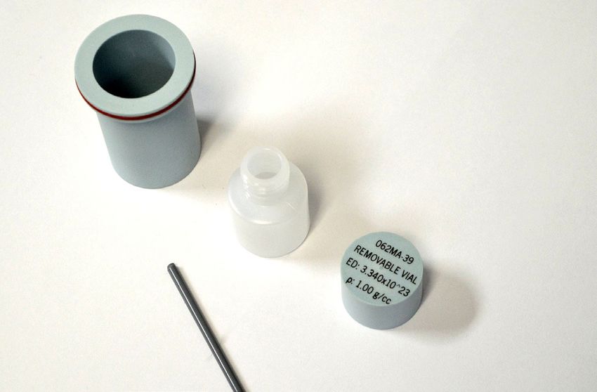
CBCT ELECTRON DENSITY & IMAGE QUALITY PHANTOM SYSTEM

  SYSTEM CONFIGURATIONS

                          11                  12       8   7   6                 5   4

                 2

                 10

                                                                                            1
             9

                                        3

                               CBCT ELECTRON DENSITY AND IMAGE QUALITY PHANTOM
                                                Model 062MQA
                                               Components 1-12

ELECTRON DENSITY PHANTOM                    CBCT ELECTRON DENSITY PHANTOM        IMAGE QUALITY PHANTOM
        Model 062M                                    Model 062MA                    Model 062QA-35
      Components 1-3                                Components 1-10                 Components 11-12

                                                       5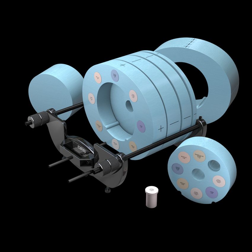
OVERVIEW & SPECIFICATIONS

       ELECTRON DENSITY PHANTOM
       MODEL 062M

The Electron Density Phantom, Model 062M, is used to
account for tissue heterogeneity in radiotherapy treatment
planning. The phantom is used with a CT scanner to provide
precise correlation between electron density of tissues and their
CT number in Hounsfield units (HU).
The Model 062M consists of 2 nested disks made from Plastic
Water®-LR. They can represent both head and abdomen
configurations. Nine different tissue equivalent electron density
plugs can be positioned at 17 different locations within the scan
field. Included is a water vial plug that can be filled with any
fluid. Optional distance marker plugs enable quick assessment
of the CT scanner’s distance measurement accuracy.                                                    FEATURES:
                                                                                                           • Evaluate CT scan data
                                                                                                           • Correct for inhomogeneities
                                                                                                           • Document relationship between CT number and tissue
                                                                                                             electron density
                                                                                                           • Simulate indicated tissue within the diagnostic and
                                                                                                             therapeutic energy range
                                                                                                           • Quick assessment of distance registration (optional)
SPECIFICATIONS MODEL 062M - TABLE 1
                                  Electron Density Head Insert: Ø 180 mm x 50 mm (Ø x D)
 OVERALL DIMENSIONS:              Electron Density Body without Head Insert: 330 mm x 270 mm x 50 mm (W x H x D)
                                  Electron Density Plugs: Ø 30 mm X 50mm (Ø X L)
                                  Electron Density Head Insert: ≈ 0.950 kg (2 lb)
 WEIGHT:
                                  Electron Density Body without Head Insert: ≈ 2.1 kg (4.7 lb)
 MATERIALS:                       Water and Tissue Equivalent Epoxy Resins

                                                                                                            *PHYSICAL DENSITY,    ELECTRON DENSITY,     RED
 QTY      PART NO.                DESCRIPTION                                                               g/cc                  x 1023 electrons/cc   (RELATIVE TO H2O)
 1        062MA-01                Electron Density Head Insert                                              1.029                 3.333                 0.998
 1        062MA-02                Electron Density Body without Head Insert                                 1.029                 3.333                 0.998
 2        062A-04                 Lung (Inhale) Equivalent Electron Density Plug                            0.205                 0.668                 0.200
 2        062A-05                 Lung (Exhale) Equivalent Electron Density Plug                            0.507                 1.658                 0.496
                                  Breast (50% Gland / 50% Adipose) Equivalent
 2        062A-06                                                                                           0.99                  3.261                 0.976
                                  Electron Density Plug
                                  Solid Trabecular Bone (200 mg/cc HA) Equivalent
 2        062A-08                                                                                           1.16                  3.730                 1.117
                                  Electron Density Plug
 2        062A-09                 Liver Equivalent Electron Density Plug                                    1.07                  3.516                 1.052
 2        062A-10                 Muscle Equivalent Electron Density Plug                                   1.06                  3.483                 1.043
 2        062A-11                 Adipose Equivalent Electron Density Plug                                  0.96                  3.171                 0.949
                                  Solid Dense Bone (800 mg/cc HA) Equivalent
 2        062A-15                                                                                           1.53                  4.862                 1.456
                                  Electron Density Plug
                                  Solid Dense Bone (1250 mg/cc HA) Equivalent Electron
 1        062A-27                                                                                           1.82                  5.663                 1.695
                                  Density Plug

 1        062MA-39
                                  Water-fillable Electron Density Plug, Ø 1" remov-                         1.00                  3.340                 1.000
                                  able vial inside (Real water data provided)
 1        062M-30                 Set of 2 Feet for Model 062M
 1        062M-40                 Soft Carry Case for Model 062M
* Physical Density - The actual physical density of the insert can vary within ± 1% of the manufacturing target density.
Note: CIRS strongly recommends that the user inputs the electron density whenever prompted for material data by the TPS.

                                                                                             6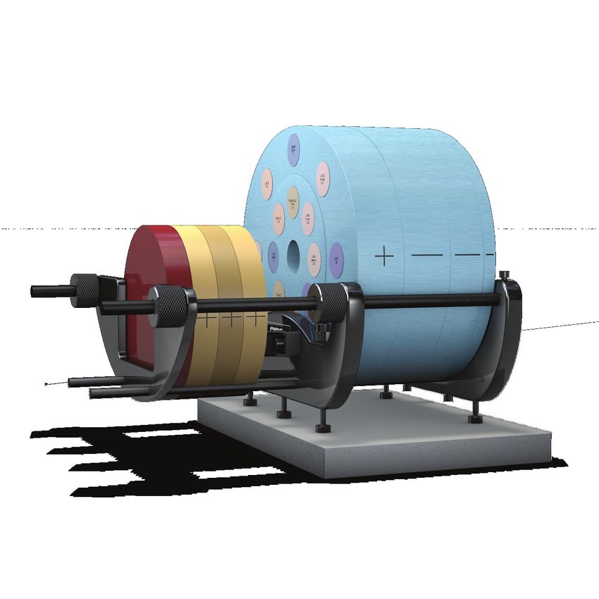
OVERVIEW & SPECIFICATIONS

       CBCT ELECTRON DENSITY PHANTOM
       MODEL 062MA

The Cone Beam (CBCT) Electron Density Phantom is an
extended version of the CIRS Model 062M Electron Density
Phantom specifically designed for Cone Beam CT Imaging
systems. Preliminary data shows that there may be differences
between the HU readings for Diagnostic CT and Cone Beam
CT. The geometry of the Cone Beam CT requires additional
material and suggests that off central axis measurements
should be taken.
The phantom is a valuable tool for CT number to electron
density calibration in volumetric imaging. Reliable CT calibra-
tion curves help enable treatment plan adaptation directly from
Cone Beam CT data. Additionally, the phantom can accommo-
date any ion chamber for dose measurements and validation
of tissue heterogeneity correction based on the corrected CT
calibration curve.
The Model 062MA CBCT Electron Density Phantom's size                                                       FEATURES:
covers geometries for imagers with dimensions up to 40 cm x
40 cm. It is made of Plastic Water®-LR and contains the same                                                   • Evaluate CT scan data
set of tissue equivalent electron density inserts as the standard                                              • Correct for inhomogeneities
Model 062M. Additional interchangeable slabs allow for reposi-                                                 • Document relationship between CT number and
tioning of the electron density section off axis.                                                                tissue electron density
                                                                                                               • Simulate indicated tissue within the diagnostic and
                                                                                                                 therapeutic energy range
                                                                                                               • Quick assessment of distance registration (optional)
SPECIFICATIONS MODEL 062MA - TABLE 2
 OVERALL DIMENSIONS:              330 mm x 270 mm x 250 mm (W x H x D)
 WEIGHT:                          ≈ 18 kg (40 lb)
 MATERIALS:                       Water and Tissue Equivalent Epoxy Resins

                                                                                                            *PHYSICAL DENSITY,     ELECTRON DENSITY,      RED
 QTY      PART NO.                DESCRIPTION
                                                                                                            g/cc                   x 1023 electrons/cc    (RELATIVE TO H2O)
 1        062M                    Electron Density Phantom - All standard parts (Table 1)
 1        062MA-24                50 mm Thick Bolus Slab                                                    1.029                  3.333                  0.998
 1        062MA-33                12.5 mm Thick Bolus Slab                                                  1.029                  3.333                  0.998

 1        062MA-34                37.5 mm Thick Bolus Slab                                                  1.029                  3.333                  0.998
                                  CBCT Electron Density Phantom - Annulus
 1        062MA-36                                                                                          1.029                  3.333                  0.998
                                  (100 mm Thick)
                                  CBCT Electron Density Phantom - Annulus Solid insert
 1        062MA-37                                                                                          1.029                  3.333                  0.998
                                  (100 mm Thick)
 2        062MA-32                100 mm L x Ø 30 mm Background Equivalent Plug                             1.029                  3.333                  0.998
 1        062MA-30                Holder/Support set for Model 062MA & 062MQA
 1        062MA-40                Soft Carry Case for Model 062MA

* Physical Density - The actual physical density of the insert can vary within ± 1% of the manufacturing target density.
Note: CIRS strongly recommends that the user inputs the electron density whenever prompted for material data by the TPS.

                                                                                             7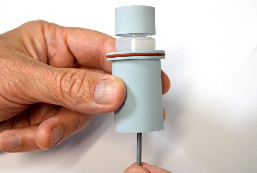
OVERVIEW & SPECIFICATIONS

      CBCT IMAGE QUALITY PHANTOM
      MODEL 062QA-35

The purpose of image quality measurements is to quantify
various image quality indicators for 3D images taken from
a selection of image acquisition and reconstruction settings
representative of clinical practices. Assessment of the image
quality parameters over time can show trends in variation of
said parameters helping the user to decide whether or not
recalibrations of the imaging system are necessary.
The Image Quality Phantom (062MQA-50) is composed of four
layers: Uniformity, Low Contrast/Magnification, CT Number
Linearity/Slice Thickness, and Spatial resolution.

UNIFORMITY LAYER
The Uniformity Layer is designed to measure the system’s
ability to produce uniform images across the field of view of
an object with highly homogeneous physical properties in all
directions.

                                                                        CT NUMBER LINEARITY/SLICE THICKNESS LAYER
                                                                        The CT Number Linearity and Slice Thickness Layer is designed
                                                                        to determine Contrast-to-Noise Ratio, CT Number consistency
                                                                        over time and Slice Thickness. Five rods made of Low-Density
                                                                        Polyethylene (LDPE), Polystyrene, Acrylic, Delrin and Teflon and
                                                                        a cylindrical air pocket (25.4 mm diameter x 15 mm length) are
                                                                        used to measure the CNR and HU. Three angled air channels
 BACKGROUND:      Plastic Water®-LR
                                                                        placed within the middle of the layer, which are arranged in an
 DIMENSIONS:      Ø 180 mm x 25 mm thickness                            equilateral triangle, are used to assess the Slice Thickness.

Note: Irregularities may be
present when imaging the
interface between phantom
layers, as shown by the green
and yellow circles in the image
to the right. These irregulari-
ties are caused by coatings
that protect air cavities and
other imaging features from
infiltration of the background                                           BACKGROUND:        Plastic Water®-LR
material during fabrication.                                             CT NUMBER          Five ø 25.4 mm (1”) x 25mm long rods made of:
The coatings do not affect the                                           LINEARITY:          •     Low-Density Polyethylene (LDPE)
performance of the phantom, as their radiation attenuation                                   •     Polystyrene
is closely matched to that of the bulk background. Further-                                  •     Acrylic
more, the imaging irregularities are isolated to the layer inter-                            •     Delrin
                                                                                             •     Teflon
face, where it is not recommended to take measurements.                                     Cylindrical air pocket ø 25.4 (1”) mm diameter x
                                                                                            15 mm long
                                                                         SLICE              Three Ø 0.8 mm x 73.1 mm long air channel
                                                                         THICKNESS:         ramps placed at 20° with respect to the transver-
                                                                                            sal plane arranged in an equilateral triangle
                                                                         DIMENSIONS:        Ø 180 mm x 25 mm thickness

                                                                    8
OVERVIEW & SPECIFICATIONS

       CBCT IMAGE QUALITY PHANTOM
       MODEL 062QA-35

LOW CONTRAST/MAGNIFICATION LAYER                                                                 SPATIAL RESOLUTION LAYER
The Low Contrast Layer assesses the system's ability to detect                                   The Spatial Resolution Layer is designed to evaluate the spatial
small differences in contrast. It contains three sets of low                                     resolution of IGRT systems. Line pair patterns from 1 lp/cm
contrast rods with linear attenuation differences of 0.5%, 1%                                    to 16 lp/cm are embedded in the background. In order to
and 2% relative to the background material. The diameters of                                     minimize artifacts, each line pair pattern is made from a mate-
the low contrast rods were chosen so as to provide a 0.5 ratio                                   rial with ≈ 350 HU greater than the background attenuation.
between two adjacent rods by cross section and volume.                                           The line pair patterns are 3D patterns, 12 mm in height along
                                                                                                 the longitudinal axis of the CBCT Image Quality Phantom. The
Additional layer features evaluate the magnification on the
                                                                                                 spatial resolution targets are arranged in a circular pattern.
orthogonal axes of the transversal image and provide input for
calculation of Point Spread Function and subsequent calcula-
tion of Modulation Transfer Function.

                                                                                                  BACKGROUND:              CIRS proprietary epoxy formulation
 BACKGROUND:             Plastic Water®-LR                                                                                 (attenuation ≈ 70 HU)
 LOW CONTRAST:           3 sets of targets Ø 10, 7, 5, 3.5, 2.5, 1.8, 1.2                         LINE PAIRS               From 1 lp/cm to 16 lp/cm (attenuation ≈ 420
                         mm x 25 mm long with attenuation differences of                          PATTERNS:                HU; a difference that is often used in cardiac
                         0.5%, 1% and 2% relative to the background                                                        angiography imaging), embedded in the
                                                                                                                           background
 MAGNIFICATION:          Four Ø 0.050 mm x 25 mm long Tungsten
                         wires which show on slices as four points,                               DIMENSIONS:              Ø 180 mm x 25 mm thickness
                         one at the center and three on a circle R55
                         mm at 0°, 90° and 225° or 0°, 135° and
                         270° (depending on scan orientation) going
                         clockwise starting at 12 o’clock.
 ALIGNMENT:              Ø Exterior 25.4 mm (1”) x 25 mm long Delrin tube
 DIMENSIONS:             Ø 180 mm x 25 mm thickness

SPECIFICATIONS MODEL 062QA-35 - TABLE 3
 OVERALL DIMENSIONS:               Ø 180 mm x 100 mm (Ø x D)

 WEIGHT:                           ≈ 2.5 kg (5.6 lb)

 MATERIALS:                        Water and Tissue Equivalent Epoxy Resins, Engineered Plastics

                                                                                                             *PHYSICAL DENSITY,   ELECTRON DENSITY,     RED
          PART NO.                 DESCRIPTION                                                               g/cc                 x 1023 electrons/cc   (RELATIVE TO H2O)
   1      062MQA-50                CBCT Image Quality Phantom

                                         Background (Uniformity, Low Contrast/                               1.029                3.333                 0.998
                                         Magnification, CT Number/Slice Thickness layer)
                                         Background (Spatial Resolution layer)                               1.11                 3.641                 1.090

   1      062MQA-30                Holder for 062MQA-50 CBCT Image Quality Phantom (assembled)

   1      062MQA-40                Soft Carry Case for 062MQA-50 CBCT Image Phantom and 062MQA-30 Holder
* Physical Density - The actual physical density of the insert can vary within ± 1% of the manufacturing target density.
Note: CIRS strongly recommends that the user inputs the electron density whenever prompted for material data by the TPS.

                                                                                             9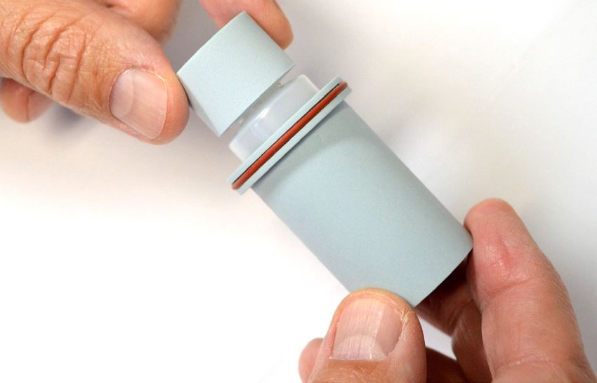
OVERVIEW & SPECIFICATIONS

      CBCT ELECTRON DENSITY & IMAGE QUALITY PHANTOM
      MODEL 062MQA

The Model 062MQA phantom provides a comprehensive tool
that can be used for both electron density calibration and im-
age quality assessment of Cone Beam CT systems integrated
in radiation therapy devices. The electron calibration function
of the phantom enhances the outcome of the adaptive radia-
tion therapy while the image quality features address the fine
balance between optimizing image quality while minimizing
radiation dose.
The 062MQA CBCT Electron Density & Image Quality Phantom
incorporates 3 phantoms:
         1. Electron Density Phantom (50 mm thick)
         2. CBCT Phantom which is used with the Electron
            Density Phantom
         3. CBCT Image quality phantom
The 100 mm thick body section has a central hole that receives
the CBCT Image Quality Phantom. Each Bolus slab is drilled to
accommodate an ion chamber insert and allow for ion chamber
measurements regardless of the position of the Image Quality
Insert. The thicknesses of the sections were selected to allow
for positioning of any of the layers containing the Image Quality
features in the central axis of the beam. Also sections of differ-
ent thickness decrease the increment with which the electron
density section can be offset from the central axis.
                                                                              FEATURES:
                                                                                 • Perform all CT Image QA tests for AAPM TG Report #1
                                                                                 • Perform dose measurements using Ionization chambers
                                                                                 • Calibrate Electron Density in multi-slice CT and Cone
                                                                                   Beam CT
                                                                                 • Perform central axis and off-set measurements
                                                                                 • Position simulated tissue materials in CT & CBCT energy
                                                                                   range at 17 different locations
                                                                                 • Optimized for volumetric imaging
                                                                                 • Quick positioning and customized loading configurations

SPECIFICATIONS MODEL 062MQA - TABLE 4

       PART NO.          DESCRIPTION

  1    062MA             Cone Beam (CBCT) Electron Density Phantom - All standard parts (Table 2)

  1    062QA-35          CBCT Image Quality Phantom - All standard parts (Table 3)

                                                                     10
OVERVIEW & SPECIFICATIONS
OPTIONAL ACCESSORIES
MODEL 062M, 062MA & 062MQA
TABLE 5
*PHYSICAL DENSITY, ELECTRON DENSITY, RED
PART NO. DESCRIPTION g/cc x 1023 electrons/cc (RELATIVE TO H2O)
062MA-07** 800 mg/cc HA in Water Equivalent - Core Insert 1.53 4.862 1.456
062MA-12** Titanium Rod Core Insert 4.51 12.475 3.735
062MA-13 Distance Marker Insert 1.029 3.333 0.998
Water Equivalent Chamber Rod with Cavity for
062MA-14-CV† 1.029 3.333 0.998
Ion Chamber
062MA-16 Water Equivalent Insert 1.029 3.333 0.998
062MA-17** 1000 mg/cc HA in Water Equivalent - Core Insert 1.660 5.243 1.570
062MA-18** 1250 mg/cc HA in Water Equivalent - Core Insert 1.82 5.663 1.695
062MA-19** ICRU Cortical Bone Equivalent Core Insert*** 1.91 5.915 1.771
062MA-20** 1500 mg/cc HA in Water Equivalent - Core Insert 1.99 6.134 1.837
062MA-21** 1750 mg/cc HA in Water Equivalent - Core Insert 2.15 6.600 1.976
Solid Dense Bone (1000 mg/cc HA) Equivalent
062A-26 1.66 5.243 1.570
Electron Density Plug
Solid Dense Bone (1500 mg/cc HA) Equivalent
062A-28 Electron Density Plug 1.99 6.134 1.837
Solid Dense Bone (1750 mg/cc HA) Equivalent
062A-29 2.15 6.600 1.976
Electron Density Plug
Water Equivalent Material Surrounding 6.4mm
062MA-41 Diameter Stainless Steel (Alloy 20) Rod Core 8.03 23.101 6.917
Electron
Water Equivalent Material Surrounding 6.4mm
062MA-42 Diameter Aluminum Rod Core Electron Density 2.70 8.008 2.398
Plug
* Physical Density - The actual physical density of the insert can vary within ± 1% of the manufacturing target density.
Note: CIRS strongly recommends that the user inputs the electron density whenever prompted for material data by the TPS.
** These inserts have a standard Ø D of 30 mm and contain a 10 mm diameter core of the indicated reference surrounded by H2O-equivalent background.
The titanium reference has a unique diameter of 6.35 mm.
*** CIRS Cortical bone reference is based on ICRU Report No.44, and represents ≃12.2% H20, 24.6% protein, 58% mineral (assumed to be Calcium Hydroxyapatite (HA)), and 5.2% monosac-
charides. CIRS further offers a series of mineral density references that mimic various HA concentrations in a pure water-equivalent epoxy background matrix.
† Purchased separately. Refer to CIRS cavity and Plug code list for available Ion Chamber Cavities. If the ion chamber cavity is not specified by customer, phantom is supplied
with Part No. 062MA-14-CV50-1 that accommodates a Farmer type ion chamber.
UPGRADE PACKAGES TABLE 6
PART NO. DESCRIPTION INCLUDES
CBCT Electron Density Phantom Annulus Insert, CBCT Electron
Density Phantom Annulus, CBCT Electron Density Phantom Bolus
1 062MA-35 Converts Model 062M to Model 062MA Section- (12.5 mm, 37.5 mm and 50 mm thick), ION Chamber Insert,
Background Insert, Holder and Stand, Soft-Sided Carry Case
CBCT Image Quality Phantom, Holder and Stand, Soft-Sided Carry
1 062QA-35 Converts Model 062MA to Model 062MQA Case
11ASSEMBLY & SET UP
CBCT ELECTRON DENSITY & IMAGE QUALITY PHANTOM SYSTEM
MODEL 062MA & 062MQA
3 5 4
SUPPORT BASE ASSEMBLY 1
2
2
6
3
9
10
6
9
8
7
6
6 7
• Identify the front handle plate, 8 which has two adjustable legs. set screws) and provided Allen wrench (do not over tighten the
7 . The front handle plate is shipped with set screws 6 already set screws).
inserted in proper places
• Slide the back handle plate 1 (easily identifiable by the presence
• Attach the two threaded nylon rods 2 to the front handle plate of three leveling feet) 9 10 through the nylon and carbon fiber
by tightening them in the threaded holes until the ends of rods rods 4 until it lies on top of the front handle plate. The plate face
are flush with the face on which the CIRS label is affixed. Secure with the CIRS label affixed should be facing towards the outside.
in place using provided set screws 6 (1/4-20 x ½" long set
screws) and provided Allen wrench (do not over tighten the set • Slide the buffer plates 5 through the nylon and carbon fiber
screws). rods until it lies on top of the back handle plate.
• Insert the two carbon fiber rods 4 in the matching holes and • Tighten two plastic knurled knobs 3 on each threaded nylon
secure in place using provided set screws 6 (1/4-20 x ½" long rod.
CBCT SECTION SET UP
1
3
2
5
4
• Set up the phantom by pushing the back handle plate 1 and • When placed on the support, the phantom sections rest on the two
adjacent buffer plate 5 against the plastic knurled knobs. 3 carbon fiber rods, 4 which align the sections with respect to each
other and on the two threaded nylon rods. 2
• Fully extended the support before adding the phantom sections
• Secure sections on the support by tightening the knurled knobs. 3
12ASSEMBLY & SET UP
CBCT ELECTRON DENSITY & IMAGE QUALITY PHANTOM SYSTEM
MODEL 062MA & 062MQA
POSITIONING
Images below show different positioning arrangements of sections, which allow for off axis Dosimetry
measurements, Electron Density off axis measurements, and axial positioning of each layer of the CBCT
Image Quality Phantom (062MQA-50).
062MQA-50
062MA-14-CV
Ion Chamber
Insert
062MQA-50 Spatial Resolution Layer 062MQA-50
(1 piece composed Low Contrast / Magnification Layer
of 4 layers) CT Number Linearity / Slice Thickness Layer 062M
Uniformity Layer Electron Density
Phantom
062MA-14-CV Ion Chamber Insert
13ASSEMBLY & SET UP
CBCT ELECTRON DENSITY & IMAGE QUALITY PHANTOM
MODEL 062MQA
“IN AIR” SET UP
1
2
3
4 7
5
6
1 CBCT Image Quality Phantom 4 Fixed length leveling leg
Suspended “in air”
5 2x Consolidating legs
2 Knurled Knobs
Secure back handle plate 6 LINAC Couch
and buffer plate in place 7 2x Adjustable leveling legs
3 Buffer plate
• The modular design of the phantom system allows for • Place the CBCT Image Quality Phantom on the support
positioning the CBCT Image Quality Phantom over the rails (carbon fiber rods) against the buffer plate, which is
LINAC couch so that “in air” measurements/tests can be secured by the knurling knobs. Carefully adjust the sup-
performed with minimal interference from the support. port and/or the LINAC couch so that the laser/field lights
Moreover, the CBCT Image Quality Phantom can be used fall on the CBCT Image Quality Phantom laser alignment
“in air” or inserted in the 100 mm bolus section to simu- marks. Make any adjustments to the level and fix the lev-
late more realistic attenuation conditions. eled position again if needed.
• To perform tests/measurements “in air,” extend the sup-
NOTE: The support is shipped with the fix length level-
port and place it on the LINAC couch. Add the bolus and
ing leg fully inserted in its thread insert. If the user wants
electron density sections on the couch side to serve as
more clearance for the three point leveling scheme then
counterweight. Configure the support as shown above.
the extra clearance can be obtained by unscrewing the
Be sure that the counterweight actually weighs more than
threaded stud of the fix length leveling leg from the thread
the part that is suspended “in air”.
insert.
• Level the support using the provided Allen wrench (not
• Follow the same procedure to have the CBCT Image
shown in image) and bring the LINAC laser field lights in
Quality Phantom set up “in air” while it is inserted in the
coincidence with the laser alignment marks engraved on
100 mm section. In this set up the user must use all the
the bolus sections. Secure this position by slowly twisting
remaining bolus sections and the electron density section
the consolidating legs 5 using the Allen wrench until they
(body plus head) as counterweight.
reach the LINAC couch.
14ASSEMBLY & SET UP
CBCT IMAGE QUALITY PHANTOM
MODEL 062QA-35
The CBCT Image Quality Phantom includes a Holder (062MQA-30) which comes assembled. This is provided as a convenience
for when the user wants to use the Model 062QA-35 apart from the CBCT Electron Density Phantom.
“ON-THE-COUCH” SETUP
Level in three point scheme
using legs #1, #2 and #4
6
1
4 2
3
5
1 Leg #1 4 Leg# 4
2 Leg #2 5 LINAC Couch
3 Leg #3 6 Counterweight (NOT INCLUDED)
Place on the support before leveling
“IN-AIR” SETUP
Level in three point scheme 6
using legs #1, #2 and #3
1
2
4
3
5
When the CBCT Image Quality Phantom is being used with the holder, a counterweight heavier than 3 kg is recommended for the
"on the couch" set up, but is required for the "in air" set up. After extending and placing the support on the couch, the counter-
weight should be placed prior to placing the CBCT Image Quality Phantom on the support rails.
15ASSEMBLY & SET UP
WATER-FILLABLE ELECTRON DENSITY PLUG
MODEL 062MA-39
062MA-39 insert with removable vial and Push-Rods
Use Push-Rod provided to push the vial out of insert through the small hole in the bottom of the insert.
Fill vial (middle) with desired liquid and screw the lid onto the Insert vial back into the insert ensuring the lid is leveled with the
vial. insert. Please note that parts are machined with tight toler-
ances, there will be some friction.
16DATA COLLECTION & ANALYSIS
CBCT ELECTRON DENSITY & IMAGE QUALITY PHANTOM SYSTEM
MODEL 062M, 062MA & 062MQA
TREATMENT PLANNING
• Set up with inserts in desired locations. of the push rod.) Do no remove the shell cap that is glued
to the vial's top cap. Fill with water or desired contrast
• Scan phantom using normal abdominal (or head for small
agent, and tighten the shell cap so that it is flush with the
section) scan protocol.
face of the plug that encapsulates the water vial.
• Record CT “region of interest” (ROI) values for each insert
in each location. • CTU OF HOMOGENEOUS SIMULATED TISSUES
• Change location of inserts as desired and repeat scan/ The phantom accommodates 8 (eight) pairs of tissue-
record sequence. equivalent plugs and a water vial (encapsulated in a
• For CBCT Scanners: Loosen the rod and knobs and containing plug). All plugs are optimally positioned to
place the phantom body section (062MA-02) in a offset obtain maximum CTU information from a single exposure
position as shown below. Repeat the above sequence of while minimizing artifacts (See page 24). Water is placed
data collection. Use a curve fitting algorithm to determine in the middle of the phantom as a reference, and one
the CT ROI data for each tissue. This can now be entered of each tissue-equivalent plug is spread to a peripheral
into treatment planning software with data conversion (“body”) and a centralized (“head”) location. Since some
(using relative electron density factors (RED) listed on the CT scanners display significant CTU variations depend-
specification page of this technical manual). ing on an object’s location in the gantry, this method of
positioning is beneficial for single exposure evaluation in
each location.
DIAGNOSTIC CT CONE BEAM CT CONE BEAM CT
CTU variations can be tested by comparing an exposure
of the Electron Density Phantom (062M) facing front,
with an exposure of the phantom turned in the opposite
direction. Users are free to determine the location of each
insert, although configuration options may be limited due
to situations where single (optional) inserts are chosen for
evaluation.
If the user is using the “head” section alone or with the
electron density image quality insert (062QA-35), it is
advisable to use one of each tissue-equivalent insert for a
quick measurement of a full range of densities.
ctron Density Phantom CBCT Electron Density Phantom CBCT Electron Density Phantom
tandard Configuration Central Axis Configuration Offset Configuration
• DISTANCE MEASUREMENTS
An optional distance marker insert with small longitudinal
holes is available. Measure the distance between holes
QUALITY ASSURANCE TESTING using scanner “caliper” function and compare to actual
QA testing can be as thorough as the user may require. Scan- distance measured on the phantom with a ruler or caliper.
ner manufacturer’s recommendation should be followed in
developing a QA plan. Phantom scanning provides a method
for learning about the stability of the scanner in question and its
ability to image and display various tissues.
• CTU OF H2O
The Real Water Electron Density Plug (062MA-39), which
incorporates a Ø 25.4 mm (1”) vial, allows for scanning
of regular water at various positions in the scan field with
beam hardening effects in existence. A good QA practice
involves keeping records over time of the CT value of the
H2O insert in various locations. Alternatively, the insert can
be used for scanning contrast agents.
Filling Instructions: Remove the vial by pushing it out of
the plug shell using the provided push rod (there is a hole
on the bottom face of the plug shell that matches the size
17DATA COLLECTION & ANALYSIS
CBCT ELECTRON DENSITY & IMAGE QUALITY PHANTOM SYSTEM
MODEL 062M, 062MA & 062MQA
EVALUATION OF EFFECTIVE ENERGY IN CT
The reference data provided below, used for this evaluation, are
the recalculated attenuations and the expected CT values for
the 800 mg HA in H20 insert.
TABLE 7
Mass Expected Linear
Attenuation, CTU Value, Attenuation,
cm2/g HU cm-1
KEV = 40 MRO = 0.6346 2652.75 MU = 0.9742
KEV = 50 MRO = 0.4132 1805.64 MU = 0.6344
KEV = 60 MRO = 0.3112 1326.01 MU = 0.4778
KEV = 80 MRO = 0.2240 875.23 MU = 0.3439
KEV = 100 MRO = 0.1879 690.57 MU = 0.2884
• Physical Density = 1.53 g/cc
• Electron Density = 4.862 x 10²³ electrons/cc
• RED (Relative Electron density to H20) = 1.456
• Based on a 4-degree polynomial fitting, the effective en-
ergy in keV is given by the following formulation:
(keV) eff=a/(CTU) + b + c (CTU) + d(CTU)2
With (CTU) = measured CTU value for the bone insert and:
a = 78387.86
b = -35.71341
c = 0.03691735
d = -7.364412 x 10⁻⁶
This formulation is valid between 50keV to 100keV.
18DATA COLLECTION & ANALYSIS
CBCT ELECTRON DENSITY PHANTOM & IMAGE QUALITY PHANTOM
MODEL 062MQA
IMAGE QUALITY OVERVIEW
The purpose of image quality measurements is to quantify
various image quality indicators for 3D images taken from a
selection of image acquisition and reconstruction settings rep-
resentative of clinical practices. Assessment of the image qual-
ity parameters over time can show trends in variation of said
parameters helping the user to decide whether or not recalibra-
tions of the imaging system are necessary. It was observed that
there is a great variation of image quality parameters based on
the position of a testing feature within the imaging volume. To
account for such facts and for consistency in time and space
both the CBCT Electron Density Phantom (062MA) and CBCT
Image Quality Phantom (062QA-35) were designed to allow
the positioning of any of the image quality features (layers of Engraved Laser Marks on
062QA-35) in the central transversal plane of the CBCT beam. 062MQA & 062MA Sections
Laser marks are engraved on three sides on all CBCT Electron
Density Phantom sections as well as on each layer of CBCT Engraved Laser Marks on
Image Quality Phantom. CBCT Image Quality Phantom
INITIAL PHANTOM SET UP
The design of the phantom system allows for the same align- • The positioning of the phantom system with respect to
ment to the laser lights/field lights system regardless of the the LINAC/CT laser and field lights should be verified
configuration chosen for testing. Remember that the phantom again during the image analysis stage of testing. There are
system is modular allowing the user to order/select just the three testing features designed to verify the positioning/
parts that form the configuration most appropriate for the mea- alignment of the phantom system. All theses positioning/
surements to be performed. alignment check features, some of which play a role in im-
age QA testing, are embedded in the Image Quality Insert
• Set up the holder/support on the table.
(062QA-35). These positioning/alignment check features
• Place the desired sections of the phantom system on the are:
holder/support. If the “in air” configuration is chosen re-
- Ø 25.4 mm (1”) x 25.4 mm L machined Delrin ring
member to place first on the support the sections chosen
(embedded in Low Contrast Layer/Magnification
to play the counterweight role and then the sections to be
layer). CBCT/CT software specific distance measure-
tested on the overhang portion of the support.
ment tools should yield equally orthogonal diameters,
• Tighten/secure the phantom sections in place (see Sec- when the phantom is properly aligned.
tions Set Up).
- Low Contrast Layer/Magnification layer contains
• Align the whole phantom system to the laser/field lights by four wires (seen as bright spots in transversal images),
superimposing the lights on the top engraved laser marks. one in the center, one on the vertical axis, one on the
horizontal axis, and one at 45° from the horizontal
• Raise or lower the LINAC/CT couch until the laser/field
axis. Use of any CBCT/CT orthogonal measuring/visu-
lights are superimposed on the lateral engraved laser
alization tool should show the parallelism of the wires
marks. If the lights are not collinear with the engraved
to the image axes.
laser marks, adjust the two leveling feet of the phantom
system support until the superimposition/co-linearity of - A well positioned/aligned phantom should yield
lights - laser marks is obtained, then consolidate the new equal lengths of the slice thickness ramps, which are
position using the two consolidating legs. embedded in the CT Number Linearity/Slice Thick-
ness layer.
• Verify again the superimposition/co-linearity of lights to the
top laser marks and adjust if necessary by lateral transla-
tion of the LINAC couch and/or phantom system.
19DATA COLLECTION & ANALYSIS
CBCT IMAGE QUALITY PHANTOM
MODEL 062QA-35
UNIFORMITY
Uniformity is defined as the system’s ability to produce a uni-
form image across the entire field of view (FOV) when an object
with homogenous density is scanned.
• In CBCT systems there can be variation between the
uniformity measurements taken in the central plane of
the beam and offset from this plane due to the specifics
of the CBCT imaging geometry. It is recommended that
measurements with the Uniformity layer placed axial and
off central axis be taken.
• To account for the influence of beam hardening and the
scattering observed in volume imaging, measurements
taken with the Image Quality Insert (062QA-35) inserted
in the CBCT Image Quality Phantom should be com- FIGURE 1. ROI MEASUREMENTS
pared with measurements taken using the Annulus Solid
(062MA-37).
CT NUMBER LINEARITY
There are different methods to analyze uniformity:
Assessment should be performed in different locations within
A value for uniformity can be calculated using one of the follow- the scanned 3D volume. The effective value of the CT Num-
ing formulas: ber for each reference insert is dependent on the computa-
tion used and the spectrum of the beam energy. Thus, these
(CT#max - CT#min ) values may vary from published data.
U= (1)
(CT#max + CT#min ) /2 • The numbers provided (Table 8) are for reference only.
If the phantom system was ordered in a configuration
that includes the electron density sections (062MA-01
(CT#Average (peripheral) - CT#Average (center) ) and 062MA-02) then it is recommended that a thorough
U= (2)
CT#Average (center) electron density calibration be performed. Calibration en-
sures that the system is optimized for CT Number linearity
To evaluate the uniformity using the above formulas it is recom- assessments.
mended that at least five ROI measurements are taken (Figure
TABLE 8
1). The ROI should be approximately equal in size and should
encompass an adequate number of pixels. Physical Expected CT#
Material
Density, g/cc (on a 12 bit scale)
Formula (1) can be used for each individual ROI, or “max” and
“min” can refer to the maximum and minimum pixel values Air 0.00 ≈ - 1000
averaged over each ROI.
LDPE 0.92 ≈ -97
In formula (2) the CT#Average (peripheral) is calculated from all the Polystyrene 1.05 ≈ -40
peripheral ROIs.
Acrylic 1.18 ≈ +120
• Use a CBCT/CT software profiling or histogram measuring
function to assess uniformity. Delrin 1.41 ≈ +360
Teflon 2.20 ≈ + 1080
• The displayed image of the uniformity layer should show
no “streaking” artifacts.
• For spiral multi-slice acquisitions ensure that any part of • After the scan is performed, use the window and level
the spiral that contribute to the image is constrained to be functions along with ROI tool to measure the CT number
within the volume of the uniformity layer. of each rod. Use ROI that cover the center of each CT
Number rod with an area of approximately 50% from that
of the rod diameter
(R ROI = 12.7 / √2).
20DATA COLLECTION & ANALYSIS
CBCT IMAGE QUALITY PHANTOM
MODEL 062QA-35
CONTRAST-TO-NOISE RATIO (CNR)
CNR gives an indication of an imaging system ability to distin-
guish the difference between two structures in the presence of
image noise. CNR is expressed as the ratio of the difference in
mean gray level between two objects (a.k.a. contrast) by the
standard deviation of the noise.
• One formula that can be used to calculate CNR is:
CNR = |GA - GB| / (σN), where GA is the mean gray level of
object A, GB is the mean gray level of object B, and σN is
the image noise.
• If GA is calculated for an ROI placed over one of the CT
Number rods then GB and σN should be calculated for an
ROI adjacent to that respective rod.
SLICE THICKNESS
Slice thickness evaluation can provide the user with valuable
information about the systems ability to accurately reconstruct
imaged geometry. Therefore, it is recommended that the slice
thickness be calculated from images of the slice thickness layer
taken in different places within the FOV.
The results of this test are highly dependent on phantom align- FIGURE 3. SLICE RECONSTRUCTION
ment thus the user is advised to carefully align the phantom
during the set up phase.
• Since there is a variation in the length of visible slice thick-
ness ramp projections, it is recommended that a similar • Place ROI over all the ramp projections and one over the
approach to the one described for magnification test be background (Figure 4). Record the minimum HU value
taken. Select a good slice to be analyzed. (since the slice thickness measuring ramps are air chan-
nels, the minimum value is the CT Peak Number “P”) for
• Slice thickness is expressed as (thickness in mm in each ramp projection ROI. Record the mean HU value of
this case) the value at “full with at half maximum value” the background ROI (value “B”) (Figure 4).
(FWHM) (Figure 2). For slice thickness evaluations
fmax = largest CT number in absolute value (in this case
the minimum HU value), which represents the peak of the
slice thickness ramp projection, while ½*fmax is the value
of the pixel corresponding to the voxel that encloses 50%
from the slice thickness ramp structure and 50% back-
ground material (Figure 3).
FIGURE 4.
FIGURE 2. SLICE PROFILE
21DATA COLLECTION & ANALYSIS
CBCT IMAGE QUALITY PHANTOM
MODEL 062QA-35
• For each individual ramp projection calculate the CT50 LOW CONTRAST VISIBILITY
and adjust the window to a low value (W = 4 for example)
and the level to the calculated CT50 (Figure 5). The length The low contrast visibility (resolution of closed attenuations) is
of the slice thickness ramp projections that needs to be highly subjective depending on the individual performing the
measured stands out in the image. test. It is recommended that the user be more concerned with
the consistency of the test rather than the absolute contrast
and size threshold established by a particular test.
• As explained, for the uniformity test it is recommended
to assess the low contrast visibility with the low contrast/
magnification layer positioned in different locations within
the imaged 3D space.
• Scan the phantom system in a configuration that is
deemed the most appropriate for the scanning protocol.
Adjust the window and level settings for the best image
display.
• The smallest discernible target defines the limit of the low-
contrast detectability.
• If the low contrast visibility is determined through a quan-
FIGURE 5. titative method, average the measurements made from
several scans.
• Since the ends of the slice thickness ramp projections are • For a more objective evaluation of low contrast visibility
hard to identify, it is recommended that the user adjust the user may construct a contrast detail curve. The shape
back the window and level to see if the right ends were of the curve is however dependent of on scan parameters
selected (Figure 6). (mA, kV, etc) and reconstruction algorithms.
MAGNIFICATION/SPATIAL LINEARITY
Tests should be performed in different locations within the
scanned 3D volume.
• Use the visualization software's distance measuring tool to
measure the distance between the central tungsten wire
and the wires arranged on the circle with a radius R = 55
mm. Measured distances that are equal to actual distanc-
es show that the geometric accuracy of the CBCT/CT is
such that the actual divergence of the x-ray beam matches
the divergence assumed in the reconstruction algorithm.
FIGURE 6.
• One way to ensure that the right points are selected for
distance measurements is to place an ROI over one of
• Average the three measured distances and multiply the the wires and then to determine the maximum CT number
result with “tan (20°)” (2.36397). The calculated value is the value for that ROI.
slice thickness at FWHM.
• Then, using a very narrow window adjust the level close
to that maximum value (Figure 1), which will show just the
pixels that have the maximum CT Number value. The dis-
tance measurements should be done between these pixels
(Figure 7. Note that the distance at 45° may not equal the
mathematically calculated distance because the measure
distance tool jumps from center of pixel to center of pixel).
22DATA COLLECTION & ANALYSIS
CBCT IMAGE QUALITY PHANTOM
MODEL 062QA-35
MODULATION TRANSFER FUNCTION (MTF)
The visual evaluation of spatial resolution based on line pairs/
cm is subjective depending on a series of factors chief among
them being the visual acuity of the observer.
• To eliminate the subjectivity of the visual spatial resolution
evaluation the user can calculate the “Modulation Transfer
Function” of the imaging system using a Droege-Morin
algorithm applied to the line pairs/cm patterns.
• Also, the MTF, which is 2D FFT (Fast Fourier Transforma-
tion), can be calculated using the tungsten wires from the
low contrast/magnification layer, which in this case play
the role of “delta input signals”.
• Both the Droege-Morin and 2D FFT algorithm can be dif-
FIGURE 7. ficult to perform manually so the user is advised to employ
specialized software (Figure 9).
FIGURE 8.
SPATIAL RESOLUTION
The 1 to 16 line pairs/cm patterns are used to visually assess
the imaging system's ability to resolve fine detail, respectively
lines of high contrast placed close
together.
The image should be adjusted for the best image visibility using
the tools provided by the visualization software.
FIGURE 9. FFT/ INVERSE FFT
23DATA COLLECTION & ANALYSIS
CBCT ELECTRON DENSITY & IMAGE QUALITY PHANTOM SYSTEM
MODEL 062MA & 062MQA
DOSIMETRY ARRANGEMENTS & MEASUREMENTS
Both 062MA CBCT Electron Density Phantom and 062MQA CBCT Electron Density & Image Quality Phantom are designed to
allow for dosimetry measurements in the central location of the Electron Density Head section or in special cases in any other loca-
tion of the 062M.
When the section arrangement is such that the CBCT Electron Density Body with Head Insert is at one end of the phantom,
dosimetry measurements (see image on lower right) can be taken in locations other than the central hole of the CBCT Electron
Density Head Insert by exchanging the Ion Chamber insert with any of the Electron Density inserts (plugs).
When the Ion Chamber insert is not in use, one or both Ø 30 mm x 100 mm Long Background Equivalent Inserts can be placed in
the central hole of bolus sections depending on the arrangement.
24DATA COLLECTION & ANALYSIS
ELECTRON DENSITY
SAMPLE TEST DATA SHEET
The arrangement below shows each plug optimally positioned to obtain maximum CTU information from a single exposure while
minimizing artifacts.
Muscle
Batch # _________
CTU ___________
Bone 800
Adipose Dense Bone
Batch # _________ Batch # _________
CTU ___________ CTU ___________
BR 50/50
Batch # _________
CTU ___________
Bone 200
Trabecular Bone Liver
Batch # _________ Batch # _________
CTU __________ CTU ___________
Lung Exhale Lung Inhale Plug w/ Water Lung Exhale Lung Inhale
Batch # _________ Batch # _________ Batch # _________ Batch # _________ Batch # _________
CTU ___________ CTU ___________ CTU ___________ CTU ___________ CTU ___________
Muscle Adipose
Batch # _________ Batch # _________
CTU ___________ CTU ___________
Bone 800
Dense Bone
Batch # _________
CTU ___________
Bone 200 BR 50/50
Trabecular Bone
Batch # _________
Batch # _________
CTU ___________
CTU __________
Liver
Batch # _________
CTU ___________
25DATA COLLECTION & ANALYSIS
ELECTRON DENSITY
TEST DATA SHEET
TEST DATE:_______________ PHANTOM S/N:______________
PHANTOM S/N:______________ DATE:_______________
Batch # _________
CTU ____________
Batch # _________ Batch # _________
CTU ____________ CTU ____________
Batch # _________
CTU ____________
Batch # _________ Batch # _________
CTU ____________ CTU ____________
Batch # _________ Batch # _________ Batch # _________ Batch # _________ Batch # _________
CTU ____________ CTU ____________ CTU ____________ CTU ____________ CTU ____________
Batch # _________ Batch # _________
CTU ____________ CTU ____________
Batch # _________
CTU ____________
Batch # _________ Batch # _________
CTU ____________ CTU ____________
Batch # _________
CTU ____________
TESTER: _______________________
26HANDLING & WARRANTY
HANDLING INSTRUCTIONS RETURNS
If you are not satisfied with your purchase for any reason,
It is recommended to store phantom and its inserts in the please contact Customer Service or your local distributor prior
provided carrying case. In order to minimize the shrinking/col- to returning the product. Visit https://www.cirsinc.com/distribu-
lapsing of the phantom’s holes (shrinking/collapsing magnitude tors/ to find your local distributor. Call 800-617-1177, email
can be up to a few tenths of microns) due to the material nature rma@cirsinc.com, or fax an RMA request form to 757-857-
and long term storage it is recommended that the caring case 0523. CIRS staff will attempt to remedy the issue via phone
that stores the phantom is laid on one side so as the phantom’s or email as soon as possible. If unable to correct the problem,
sections have the holes in a vertical orientation. Also, it is rec- a return material authorization (RMA) number will be issued.
ommended that for long term storage all the phantom’s holes Non-standard or “customized” products may not be returned
are fitted with the appropriate matching parts. for refund or exchange unless such product is deemed by
CIRS not to comply with documented order specifications. You
must return the product to CIRS within 30 calendar days of
WARRANTY the issuance of the RMA. All returns should be packed in the
original cases and or packaging and must include any ac-
All standard CIRS products and accessories are warranted by
cessories, manuals and documentation that shipped with the
CIRS against defects in material and workmanship for a period
product. The RMA number must be clearly indicated on the
as specified below. During the warranty period, the manufac-
outside of each returned package. CIRS recommends that you
turer will repair or, at its option, replace, at no charge, a product
use a carrier that offers shipment tracking for all returns and
containing such defect provided it is returned, transportation
insure the full value of your package so that you are completely
prepaid, to the manufacturer. Products repaired in warranty will
protected if the shipment is lost or damaged in transit. If you
be returned transportation prepaid.
choose not to use a carrier that offers tracking or insure the
There are no warranties, expressed or implied, including product, you will be responsible for any loss or damage to the
without limitation any implied warranty of merchantability or fit- product during shipping. CIRS will not be responsible for lost or
ness, which extend beyond the description on the face hereof. damaged return shipments. Return freight and insurance is to
This expressed warranty excludes coverage of, and does not be pre-paid.
provide relief for, incidental or consequential damages of any
kind or nature, including but not limited to loss of use, loss of
WITH RMA NUMBER, ITEMS MAY BE RETURNED TO:
sales or inconvenience. The exclusive remedy of the purchaser
is limited to repair, recalibration, or replacement of the product CIRS Receiving
at manufacturer’s option. 900 Asbury Ave
This warranty does not apply if the product, as determined Norfolk, Virginia, 23513 USA
by the manufacturer, is defective because of normal wear, ac-
cident, misuse, or modification.
PRODUCT WARRANTY PERIOD
NON-WARRANTY SERVICE
If repairs or replacement not covered by this warranty are Model 062M, 062MA & 062MQA -
required, a repair estimate will be submitted for approval before CBCT Electron Density & Image Quality 60 Months
Phantom System
proceeding with said repair or replacement.
27©2013 Computerized Imaging Reference Systems, Inc. All rights reserved. Computerized Imaging Reference Systems, Inc. has been certified
by UL DQS Inc. to (ISO) 13485:2016. Certificate Registration
Brand names, product names or trademarks belong to their respective holders.
No.10000905-MP2016.
Specifications subject to change without notice.
Publication: 062M 062MA 062MQA UG 072721You can also read