CAM strategies and functions for efficient manufacturing
←
→
Page content transcription
If your browser does not render page correctly, please read the page content below

© The helmet was programmed and produced by DAISHIN

     manufacturing
     CAM strategies
     and functions for efficient
cam strategies

Table of contents                          Page

        User interface		                    3

        2D strategies 	                     9

        3D strategies                       17

        HSC functions                       25

        5axis machining                    29

        Specialised applications            37

        Mill/turn strategies 	             47

        General functions                   53

        Feature and macro technologies     63

        Post-processors and simulation      71

        Strategy overview                   75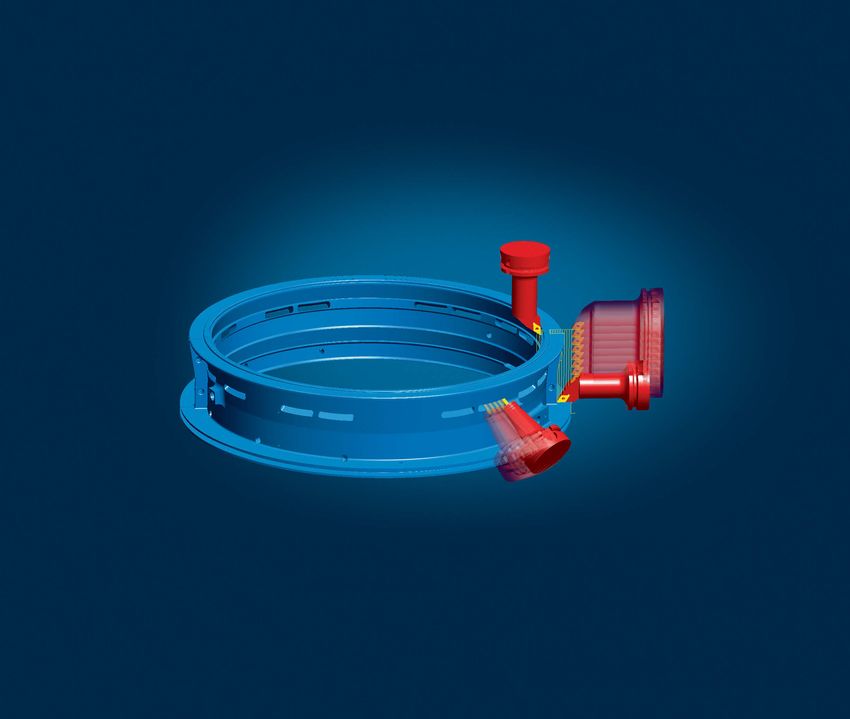
User interface

hyperMILL® covers a very wide variety
of machining strategies, ranging from
Turning and Milling with 2D, 3D and
HSC applications, all the way through
to 5axis simultaneous and dedicated
special applications. All these strategies
are accessible from a single, coherent user
interface. Administrative tools, such as job
lists or component jobs, enable a highly
transparent and reliable workflow. Func-
tions such as associative programming or
parameter programming reduce program-
ming times. This programming philosophy
simplifies training and daily usage.

                                               User interface

                                                     3
Windows-oriented user interface
➜E
asy handling, single interface for all strategies, swift and
secure programming
Working with hyperMILL® is easy, as users are already familiar with the
operating principle. The Windows look and feel facilitates user input.
Clearly structured dialog boxes with a graphical and menu-guided user
interface help users in their programming tasks.
Individual jobs as well as complete job lists can be copied within and
between projects using a drag-and-drop procedure. Tried and proven
technology sequences can be transferred between similar projects at
the click of a mouse.
Graphical user interface
Rapid result technology
➜ Fast programming and modification with minimal errors
Rapid result technology from hyperMILL® integrates automated func-
tions that take modified parameters into account. A clearly arranged job
management system, along with descriptions of problems and errors,
reduce both programming and input errors. Machining status is displa-
yed graphically, while easy setup, change and copying operations make
it possible to implement modifications and variations very quickly.
Dialog boxes with plain text
instructions
4 Erroneous entries are marked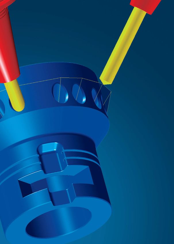
Job list
➜P
arallel calculation and programming, structured procedures
and job storage
With hyperMILL®, several projects can be open at the same time – while
one project is being calculated, another one can be programmed. A
single job list can be used for all machining strategies, from turning to
5axis simultaneous machining. The job lists are stored directly in the
CAD model. All relevant data is automatically integrated and linked
and can be retrieved at any time.
Tool list
Job list with stock management
Compound job
➜ F or well-structured job lists
Compound jobs help users to improve their project organisation and
management. A job list consists of several compound jobs. Users can
structure these jobs according to aspects such as machining process,
geometry, 3D position or tool orientation. Thus,
����������������������������
it is possible to cre-
ate structured lists containing many hundreds of programming steps.
Furthermore, the various jobs can be shown or hidden as a group.
User interface
Clear structuring according
to job group 5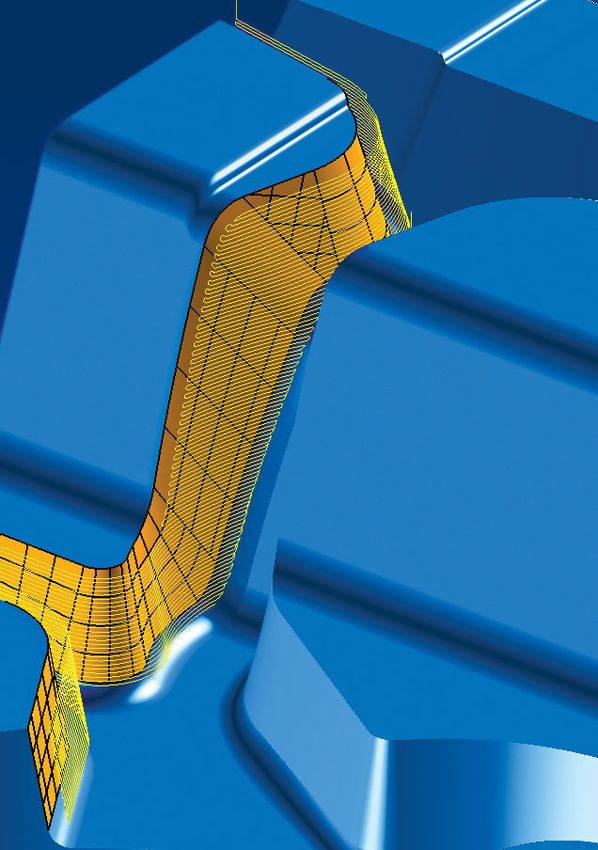
Associative programming

                                  ➜T
                                    ime-saving programming with associative copies

                                  This functionality allows users to work more flexibly and quickly edit
                                  common machining strategies where only few parameters differ across
                                  several steps in a job.

                                  Associative jobs permanently link all parameters with an original refe-
                                  rence job. Changes to the reference job are automatically copied to the
                                  associated jobs. Any individually definable parameter for a job step can
                                  be unlinked from the template by a simple mouse click so that it can be
                                  defined differently for this job step.

                                  All parameters that have been unlinked from the job template are dis-
                                  played in a separate window of the job step where they can be edited.

    Input screen

                                  Parameter programming

                                  ➜ Flexible changes and fast variant programming

                                  Programming with parameters enables the description of dependencies
                                  and consequently a rational modification with user-defined variables.
                                  This makes it possible to quickly implement variations and changes.

    Application of variables

                                  Defining zero points

                                  ➜C
                                    ustomising aspects such as positional tolerances
                                   or multiple clampings
                                  By defining zero points, positional tolerances and positions can be flex-
                                  ibly and transparently customised to current requirements. Each defined
                                  zero point is assigned a unique ID, and during post-processing this
                                  unique ID is translated into a corresponding NC code by means of a zero
                                  point table. This feature also allows the definition of multiple zero points.

6                              The new zero point appears as an entry in the frame browser.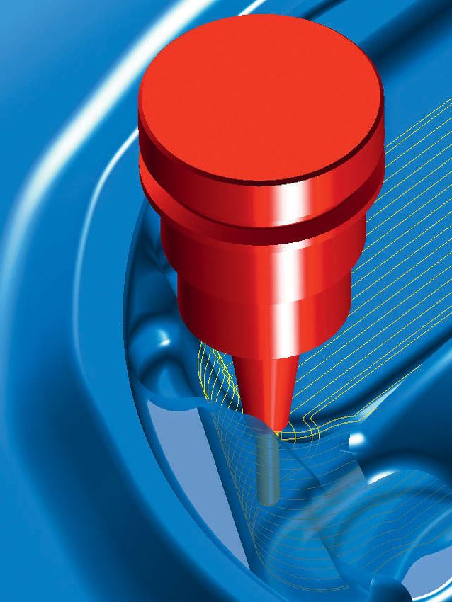
Global editing

                    ➜ Fast and easy editing across within multiple jobs

                    hyperMILL®'s user interface offers additional options to edit parameters
                    through several jobs simultaneously. Next to central parameters such as
                    surface, depth, allowance or infeed, various other geometry selections
                    such as milling or milling surfaces and even macros can be changed
                    within multiple jobs.

Editing screen

                    Extended setup

                    ➜ Improved management of data and files used in hyperMILL®

                    This function simplifies the handling, entry and configuration of di-
                    rectories containing essential hyperMILL® data such as postprocessor
                    information, machine definitions and NC files. When saving a CAD model,
                    a backup copy can be created automatically. The storage location and
                    number of backup copies are freely definable.

                                                                                               User interface

                 Setup definition                                                                     7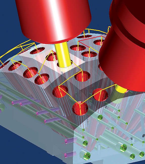
2D strategies

hyperMILL® enables the efficient program-
ming and processing of typical 2D tasks.
High-performance 2D contour milling, intel-
ligent feature technology and the support
of controller-specific NC formats are just a
few of the reasons why.
9
    2D strategies
Face milling
➜ Large surfaces
With the face milling strategy, flat areas can be machined quickly and
simply in one-way or zigzag paths. This allows several independent
surfaces to be machined in a single operation.
Zigzag mode with filleted path links
Pocket milling
➜O
pen and closed pockets with or without islands
and circular or square pockets
In this way, any pocket can be machined, even if it includes islands and
additional pockets with various heights and depths. This strategy always
seeks a start point where the plunging occurs outside of the material.
If this is not possible, a stepdown is made directly in the material via a
ramp or a helix, depending on the type of milling tool and setting. This
strategy also supports canned cycles for round and square pockets.
Minimised number of rapid movements and dwell time
Automatic feature Complete machining Supports 2D controller
10 recognition of the bottom cyclesContour milling
➜ Optimised machining of open and closed contours
The contour milling strategy is used to machine complex contours. A
selection can be made between centre path and contour path, including
G41/G42 tool path compensation. hyperMILL® automatically prepares
the contours, detects bottlenecks and self-cuts and prevents collisions
with defined safe zones.
The “Automatic orientation”, “Fast travel optimisation” and “Contour
sorting” functions assist users while programming models with multiple
contour areas or for machining automatically detected pocket features.
The automatic search feature for starting points can be used together
with intelligent approach and retract macros to ensure that infeeds and
transition movements are always performed in the most suitable areas
for the technology in use. Other functions such as automatic vertical step
down, multiple infeeds and definition of additional finishing offsets al-
low users to make effective and reliable use of their tools.
Machining with multiple Z-infeeds
2D trimming against the model...
...with automatic cut division Fillet outside edges… ... with extended edges 2D strategies
Optimisation functions
Checking self-cut, bottleneck Spiral machining down With multiple lateral infeed
and collision to the bottom 11Playback
➜S
imple creation of toolpaths
Toolpaths can be generated manually by moving the tool across the mo-
del with the mouse. Once defined, hyperMILL® performs a collision check
for the tool against the model. If a collision is detected, the software mo-
difies the tool paths to place them at collision free points on the model.
Easy generation of NC toolpaths
With collision checks Reliable programming of machining
processes
Rest machining
➜ The machining of residual stock
For areas not accessible using large tools in 2D contour and pocket
machining, this strategy calculates separate tool paths for small milling
tools. This referencing approach automatically detects all areas that have
not been processed and machines them. It detects not only areas within
a contour, but also between different contours.
Residual stock machined with contour or pocket Tangential infeed for best surfaces
12 machining cycleDrilling
➜C
entering, simple drilling, deep drilling, drilling with
chip break, reaming and boring, thread milling and drilling,
deep hole drilling
The strategies and functions for drilling enable highly efficient program-
ming, especially in conjunction with feature and macro technologies.
Depending on the machine controller and available options, the postpro-
cessor will supports canned cycles, subroutines, point lists or will output
simple G1 movements.
In helical drilling, the milling tool cuts into the part in a spiral motion.
The user can freely define the pitch of the spiral, within the limits
of technological reason. Internal and external threads are produced
by thread milling. The option of deep hole drilling enables the milling
of very deep holes.
Drill optimisation: shortest path
Drill optimisation: X-parallel
2D strategies
Helical drilling with freely definable pitch
Programming with feature recognition 13Optimised simple drilling
➜D
rilling deep holes
Complex deep holes with various steps and cross-holes can be pro-
grammed separately using hyperMILL®. The infeeds, drilling speeds and
coolant can be controlled separately for different areas and geometry
elements such as guide bushings, pilot holes or cross-holes. Here, the
strategy detects cross-holes in the specified stock.
Automatic detection of cross-holes
Pilot hole F1, S1, M9
F2, S2, M8
F3, S3, M9
Cross-hole/breakthrough F4, S4, M9
F5, S5, M9
F2, S2, M8
Input screen for optimising process
145axis drilling
➜D
rilling with different tool angles in a single operation with
optimised toolpath lengths
The 5axis drilling function is used to simply and automatically program
drilling operations with different tool inclinations in a single operation.
An automated function calculates the tool inclination and connects all
reference points of drilling operations for the best possible path.
Within certain drill patterns, the clearance plane can be defined very clo-
se to the part, and the tool need not repeatedly go to a safety position.
For the machining of different drill patterns with different tool inclina-
tions, additional retraction positions can be defined that reduce the
path length. The movements between the drill holes and the movements
between the individual machining planes are automatically checked for
collision against the model. If collisions are detected,
Feature-supported 5axis drilling the cycle automatically positions the tool on a collision-free plane.
Drill hole optimisation reduces the paths travelled between the drill
holes in one plane. If a rotating axis movement is required, the user can
determine whether the A-axis or C-axis is used first. Furthermore, users
also have the option of using the Z-height as a sorting criterion.
Optimised tool path between holes using
different tool inclinations
2D strategies
Optimised drilling for B-axis
Optimised drilling for C-axis Optimised drilling for Z-level
1516
3D strategies                                 3D strategies

hyperMILL® offers a broad spectrum of
3D strategies. Intelligent add-ons generate
optimised machining programs for better
surfaces and shorter machining times.

                                                  17
Roughing
➜ Optimised and reliable roughing, based on current stock
calculation
All depths may be machined by contour offsets from model or parallel to
a specific axis. The stock may be generated from surface or solid models,
from extruded or revolved profiles or as a result of any previous machi-
ning process. Due to automatic stock recognition, the remaining stock
areas are easily detected and machined from any direction.
By defining minimal material removal, milling paths are optimised, and
very short and redundant movements are avoided. The 'Force contour
cutting' parameter enables the use of this strategy for preliminary finish-
ing and rest machining. As a result, a uniform offset is already achieved
during roughing. The plunge movements are optimised by entering the
Contour-parallel machining tool parameters for core diameter and core height. Here, the infeed is
calculated automatically and adapted to the tool.
Collisions are checked against the stock model and part model. When a
possible collision is recognised, the user can select to stop the process
or to adjust the toolpath laterally and continue the operation at a greater
depth.
Axis-parallel machining
Optimisation functions
Automatic plane detection Machining entire part with Avoiding full cuts Filleting corners
a constant allowance
Use for preliminary finishing Cast offset roughing Rest machining from various Lateral offset to prevent colli-
18 directions sion with shank and holderFinishing: Profile finishing
➜ Milling close to contours
Profile finishing enables collision-free machining along surfaces and
surface groups. Such machining offers a number of strategies and
optimisation functions in order to individually machine complex areas
and to adapt NC paths to the special properties of a model.
Axis-parallel machining
Contour-parallel machining
3D strategies
Tool path 90° to guide curve Tool path lateral as offset Cross-flow tool path motion Tool path motion flowing bet-
to guide curve between two guide curves ween two guide curves
Optimisation functions
XY optimisation Machining of only flat areas Profile roughing
19Finishing: Z-level finishing
➜ For steep areas
Machining is executed close to the contour on planes with a constant
Z-infeed. For optimal machining, this strategy offers several machining
functions and optimisation parameters. For closed milling areas, the
“spiral” strategy achieves the best surfaces and machining process.
Plane- or pocket-based machining Spiral machining of closed milling areas Zigzag machining of open milling areas
Optimisation functions
Machining steep areas Automatic Z-infeed Undercut machining with
adjustment lollipop or woodruff cutter
20 Plane level detectionAutomatic rest machining
➜ Rest machining
In the finishing cycle, automatic rest machining detects incomplete ma-
chined areas. After defining the reference tool and the machining
area using the boundary function, the necessary rest machining is
automatically executed.
A rest material area that has not been machined due to potential colli-
sions can be used as a reference for a subsequent machining step with
modified tools (e.g., longer tool lengths). This ensures that only the areas
that could not be completed during the first step are machined in this
next one.
The machining strategies for cavities make it possible to create grooves,
ribs, and deep or narrow slits in a single machining step. Deep areas
Rest machining of incompletely m
achined areas containing large amounts of material can be cleared completely and
effectively using a constant infeed.
Milling grooves
Bullnose endmill as refe-
rence tool
Previous job as reference With definition of machining Undercut machining with
depth lollipop mills
3D strategies
Optimisation functions
Visualisation of non-ma- Machining of only steep Machining of only flat areas Pencil milling
chined area areas 21Complementary strategy: Complete finishing
➜ Electrodes and prismatic parts
By combining Z-level finishing and profile finishing, this strategy can
automatically adapt machining to the requirements of individual regions
of a model. In accordance with the defined slope angle, machining
is divided automatically between steep and flat areas, both of which
can be processed in a spiral pattern.
Slope machining
Parallel machining paths Automatic alignment based Pocket-shaped clearing when
for flat areas on longest pocket dimension there are large distances
between paths
Complementary strategy: Equidistant finishing
➜ Models with flat and steep areas
By defining one or two guide curves, the strategy calculates the milling
paths parallel to the indicated curve. Here, the distance between paths
is not calculated in the XY plane, but rather always on the surface. In this
way, flat and steep areas can be machined in a single operation with the
same surface quality.
Machining with closed guide curve
Machining between two Spiral machining between
22 open guide curves two guide curvesComplementary strategy: ISO machining
➜ Precise machining of individual surfaces and transition radii
with uniform path distances
ISO machining can be performed with global alignment or by defining the
direction of machining with ISO curves. When machining with ISO align-
ment, the milling paths run along the ISO curves (U and V). The U and V
curves of contiguous surfaces are automatically aligned. This facilitates
machining across several surfaces without retracting the tool. The ma-
chining area can be limited by a boundary. The global alignment strategy
automatically determines the optimal milling direction based on the
longest boundary of the selected surface. The user defines whether the
machining proceeds diagonally or freely to the direction of machining.
Multiple surfaces can also be selected here. In addition, spiral machining
ISO machining with global alignment in one step without a dwell point is possible.
Complementary strategy: Freepath machining
➜ Simple engraving and edge milling
During curve machining, the cutter follows a defined contour.
This strategy can be used for especially quick engraving on a planar or
curved surface, or for deburring, chamfering or trimming 3D edges.
3D strategies
Controlling the tool path with guide curves
Complementary strategy: 3D rework machining
➜ Editing of tool paths to prevent collision
With the aid of rework machining, tool paths from a reference operation
with other tools and modified tool inclinations can be output without
recalculating the path, and checked for collisions. This can be done
on the complete tool path as well as with path sections that have been
excluded in the reference operation in order to prevent collisions.
Outputting of complete tool paths
with optimised positioning 2324
HSC functions
High-speed cutting

To respond appropriately to the strict
requirements for precision, surface quality,
tool life and machine dynamics, hyperMILL®
integrates special functions for high-speed
cutting. These functions expand many of
the 3D milling strategies.

                                                  25
Filleting of corner radii
➜ For high feed rates with continuous machine movements
For smoother machine movements and better cutting behaviour, interior
corners can be filleted. Tool path filleting is available as an additional
function with, among others, roughing, Z-level finishing, profile finishing
and automatic rest machining.
Roughing
Z-level finishing Profile finishing Rest machining
Smooth plunging
➜O
ptimal cutting conditions for constant cutter loads
With axial infeed, an optimal feed rate can be maintained and the tool
can be protected using a helix or a linear ramp.
Plunging via helix path
26Smooth infeed
➜O
ptimised tool movement between tool paths
Approaches and retracts, as well as the transition between individual pa-
ths, can be filleted. During the process, the tool can also be raised from
the surface in a smooth movement.
Smooth approach and retract movements
Spiral machining
➜ For high feed rates and optimal cutting conditions
Machining is optimised for Z-level and equidistant finishing, for
automatic rest machining and for machining closed curves with a conti-
nuous tool path – including complete or near-complete spiral infeed.
HSC functions
Continuous spiral tool path
Avoiding full cuts
➜E
ven tool load and averting tool breakage while
milling grooves
Trochoidal machining is the best strategy when milling grooves in the
HSC area. Spiral step-over movements allow larger chip loads and reduce
the time when machining larger depths of cut.
Trochoidal machining 2728
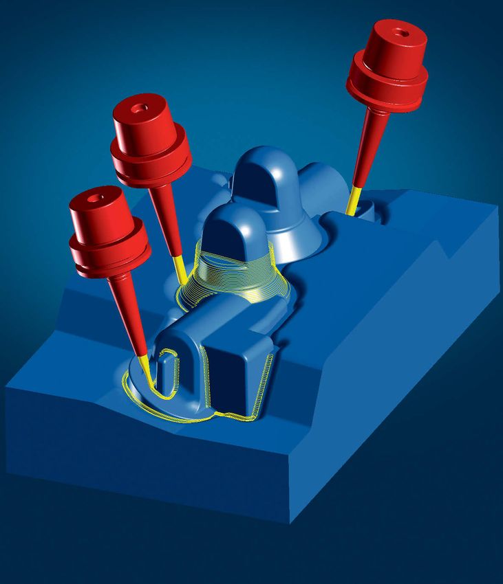
5axis machining

                                                5axis machining
For demanding geometries such as deep
cavities, high steep walls and undercuts,
3D machining is not possible because of
collisions – or it is only possible with long
tools. Machining these areas requires
precisely defined milling areas and many
different tool inclinations, which can be
accomplished without collisions using
5axis machining. Depending on the geo-
metry and machine kinematics, you can
select between 5axis machining with a
fixed tool inclination, automatic indexing
or simultaneous machining. Larger, slightly
curved surfaces and geometries that follow
leading surfaces or profiles can also be
efficiently milled using 5axis machining.

                                                   29
Multi-axis indexing with fixed tool inclination
➜A
ll 2D machining jobs from different sides
This function enables the machining of parts from different directions
with one setup. It shifts and tilts the workplane for machining. The direc-
tion of machining corresponds to the orientation of the tool. Programs
can be transformed and copied, even on multiple workplanes, without
additional job calculation.
Shifted and tilted workplane
With program part repetition Program part repetition with multiple
setup
Milling with fixed option 3 + 2
➜ A
ll 3D machining operations with the tool pivoted relative
to the direction of machining
Cutting areas can be programmed from a single machining direction
with different tool inclinations and free of collision. They can be easily
kept separate, with no overlapping or gaps occurring. The course of the
paths for neighbouring areas and the appearance of the surface can
be precisely determined. In addition, this strategy ensures that all
areas including details are completely calculated.
30 Programming with fixed tool inclinationAutomatic indexing
➜A
utomated 3+2 milling as an alternative to 5axis
simultaneous machining
Areas that require multiple tool angles for machining are programmed
and milled in a single operation using automatic indexing. This method
automatically seeks a collision-free fixed tool angle for individual milling
areas and/or toolpaths. You can choose whether perpendicular (vertical)
or angled tool orientations are preferred. With manually defined segment
limits, milling areas can also be individually separated. If necessary,
5axis simultaneous machining operations can also be used for local ma-
chining. In comparison to complete 5axis simultaneous machining, how-
ever, automatic indexing minimises machine movement. This reduces
machining times and thus minimises stress on the machines.
Automatic search for fixed tool inclination If it is not possible to calculate a collision-free fixed tool angle for
an area, then, with 5axis rest machining, for example, a subdivision
into smaller segments with different tool angles can be performed
automatically.
5axis machining
Profile finishing with optimised tool inclination
5axis simultaneous machining
➜M
achining on or near steep walls; alternative to fixed tool
inclination or automatic indexing
This 5axis machining cycle is the alternative to conventional 3 + 2 milling.
Here a tool tilt to the Z-axis is defined, which hyperMILL® automatically
changes to prevent collisions. The continuous movement of the tool
around the Z-axis is calculated by hyperMILL® either fully automatically
or as a result of defined guide curve.
Fully automatic calculation
of tool inclination
Radial tool alignment Tool axis always runs Tool axis runs locally Manual curve for movement
to Z-axis through the guide curve through the guide curve only around the Z-axis 315axis Strategies for Cavity Machining
➜ For difficult geometries such as deep cavities and
steep high walls
hyperMILL 5AXIS adds 5-axis positions to “z level Finishing”, profile
®
finishing, equidistant finishing, free path milling, rest machining and
rework machining 3D strategies. These strategies can now be used for
3+2 milling, automatic indexing and 5axis milling. Thanks to the fully
automatic calculation of tool positions, 5axis machining jobs can be
programmed as easily as conventional 3D tasks.
5axis “z level Finishing” is used to machine steep surfaces as planes
or pockets. Flat areas can be automatically excluded in this type
of finishing.
5axis z level Finishing with simultaneous machining
As with conventional 3D tasks, flat or slightly curved areas can be
machined using 5axis profile finishing. 5axis collision avoidance
allows you to mill near steep walls using a short tool in a single
step. Combined with automatic indexing, steep walls can also be
machined in the removal direction of the mould.
5axis profile finishing with automatic indexing
Simultaneous machining Fixed position
5axis equidistant finishing allows you to machine steep and flat areas in
a single operation. This strategy generates especially smooth transitions
between individual tool paths. It helps prolong the lifespan of tools and
machines and ensures the best surfaces possible.
32 5axis equidistant finishing with simultaneous machining5axis curve machining makes it possible to mill engravings without colli-
sions using short tools, even near steep walls.
5axis free path milling with automatic indexing
5axis rest machining offers all the options of 3D rest machining in
5axis machining
addition to the 5axis tool positions. Automatic indexing determines
the positions and areas that allow the part to be completely
machined in a single operation.
5axis rest machining with automatic indexing
5axis rework machining (editor) is used to convert 3D programs into
5axis programs. It also allows 3D tools that have been excluded due
to a collision to be machined as 5axis simultaneous machining jobs
or with automatically calculated fixed positions. All
����������������������
3D and 5axis tool-
paths can also be optimised to improve milling results.
5axis rework machining with simultaneous machining 335axis cutting edge machining
➜ Machining of 3D trimming tools
The strategy enables a fast reproducible machining of cutting edges.
The machining job is defined using a reference curve. After selecting the
edge and inputting the height and clearance angle, the machining job
is calculated automatically.
Exact, reproducible machining operations
5axis contour machining
➜M
illing grooves, engraving, deburring and chamfering
With this strategy the tool is guided on or relative to a curve with a fixed
orientation to the surface. Grooves, chamfers and other similar geome-
tries don’t have to be designed in detail. The automatic collision detec-
tion and avoidance functions makes programming these machining jobs
easy and reliable. If necessary, the tool orientation can also be manually
changed for particular areas.
Milling grooves
Trimming – perpendicular Chamfering – fixed tilt Engraving – perpendicular
to surface angle to surface to surface
345axis top milling
➜ Machining of large, moderately curved surfaces
Top milling reduces cutting time by allowing larger path step-overs.
High-quality surfaces are achieved by automatically adapting the tool in-
clination for concave surfaces. Machining is not limited to single surfaces
only. Furthermore, this strategy can also be used for very effective 5axis
roughing, thanks to multiple infeeds and stock detection.
Roughing a shaped pocket base
With constant optical path With optimal fit to the
width surface
5axis machining
5axis swarf cutting
➜M
achining of ruled surfaces
The side of the tool is used to machine workpiece surfaces with the swarf
milling process. Large stopovers between paths reduce the cutting time
and improve the workpiece surface finish. The tool is guided by a surface
along a reference curve. As an alternative, it is also possible to guide the
tool between two curves. Multiple axial and lateral infeeds make swarf
cutting also suitable for roughing. Machining can be precisely and simply
executed by defining stop and milling surfaces and stock tracking.
Machining ruled surface with flank contact
Machining double-curved Swarf cutting with stop
surfaces with point contact surface
35Specialised
applications
Geometries such as impellers, blisks, turbi-
ne blades, tubes and tyres pose special re-
quirements that standard strategies cannot
satisfy. For this reason, hyperMILL® offers
user-friendly special applications seam-
lessly integrated into the CAM system.
3637
Specialised applicationsBlade package: 5axis top milling
➜ F inishing blade surfaces
5axis blade top milling enables continuously spiralling finish machining
with freely definable offsets to the blade and side surfaces. The spiral
tool path can be generated as a 5axis or 4axis simultaneous machining
job. For endmills and bullnose endmills, the lead angle is automatically
adjusted such that the surfaces are not damaged and the tool always
cuts with the front edge.
Continuous spiral path
Automatic lead angle correction
Blade package: Platform machining
➜P
latform machining, trimming and deburring of surfaces
A number of 2D and 3D strategies are available for machining the plat-
forms of a blade. The 2D category includes strategies for drilling, facing,
curve and pocket milling. The various 3D operations include roughing
cycles, finishing operations for the mechanical attachment geometry, as
well as strategies for trimming, deburring or milling/machining curved
surfaces.
38 Complementary strategies for platform machiningBlade package: 5axis swarf cutting
➜R
est machining, fillet milling, machining blade walls
The tool moves in parallel or spiral paths around the blade to point-mill a
seamless transition from top-milling of the blade surfaces to the platform
surface including the fillets and to swarf-mill the platform surfaces.
A rolling ball fillet condition can be created even in conditions when the
designed fillet would ordinarily can not be fully generated due to the
platform dimensions. The tool maintains contact with the blade and a
straight boundary of the platform to achieve a perfect transition in refe-
rence to the platforms of neighbouring blades, which cannot be achieved
Specialised applications
in many CAD systems.
Blade swarf cutting
Blade package: Point machining
➜ Machining blade and root surfaces
5axis blade point milling optimises finishing at the transition between
the blade and the root surface of the top or bottom. Overlapping toolpath
for blade machining provide excellent surface qualities. Alternatively, a
rolling ball radius can be generated here.
Point machining
Surface transition with rolling ball function Transition without rolling ball function 39Multi-blade package: Roughing
➜P
re-turned stock or semi-finished workpiece
The most common roughing strategies are taking slices through the so-
lid. Machining takes place pocket by pocket between the blades. Various
roughing strategies such as “hub offset” or “shroud offset” enable con-
trol of path distribution, tool inclination and tool length to be optimally
adapted to the geometry. Plunge roughing can also be used.
Continuous pocket-by-pocket machining
Layered machining parallel Layered machining perpendi- Plunge roughing with long
to hub cular to hub narrow tools
Multi-blade package: Hub finishing
➜H
ub finishing, rest machining close to the blade
This strategy is suitable for the complete or partial finishing of hub
surfaces. With various infeed options and a scallop height function for
the area around the leading and trailing edges, the machining job can be
precisely adapted to the requirements and the machining time mini-
mised. This strategy can also be applied as rest machining near blade
surfaces.
Complete or partial machining of hubs
Shorter paths using special Shorter paths for the
40 scallop height option “pocket” infeedMulti-blade package: Blade machining
➜M
illing blade surfaces
Depending on the blade geometry, blades are machined with point
contact finishing or swarf cutting. Point milling is a very robust techno-
logy that is able to machine any blade geometry. It is used especially in
high-speed applications, in the manufacturing of prototypes or when the
blade geometry cannot be swarf cut with the necessary precision.
Specialised applications
Point milling
The flank contact with swarf cutting reduces the number of necessary
machining paths and thereby the machining time required. The best fit
of the tool to the surface is found simply by clicking the mouse. This option
simultaneously indicates the surface quality that has been achieved.
Swarf cutting
Complementary machining strategies
➜M
illing the fillet radii between the blade and hub surfaces
as well as between the leading and trailing edges
If the leading and/or trailing edges cannot be machined in a continuous
operation around the blade due to the geometry or for technical reasons,
multi-blade edge machining is applied. Milling transitional areas bet-
ween the blade and the hub surfaces is used if the model contains very
small or variable fillet radii.
Machining leading and trailing edges Milling transitional radii 41Tube package: Machining definition
➜W
ith surface or digitised data
All that is needed to define the particular machining type is a simple
curve. There are no special requirements with respect to the surface defi-
nition, the number of surfaces, the quality of surface patches, the course
of ISO curves or the surface orientation. It is possible to work directly
with the digitised data.
Simple definition of the central curve
Tube package: 5axis roughing
➜5
axis roughing with undercut tubes from the full job
This strategy is an effective alternative to machining with several jobs
required for 3+2 machining. It enables the continuous roughing of a
tube from the full job. There is spiral infeed to the bottom, and work is
executed on the plane. Optimisation functions including preventing
unnecessary movements of the rotary axes in strongly undercut tubes,
allow processing of simple and complex tube geometries.
Effective undercut machining
42 Removal from outside to inside Removal from inside to outsideTube package: 5axis finishing
➜ F ine machining of undercut tubes
5axis Tube Finishing works with a spiral or parallel tool path. Spiral
machining creates seamless surfaces. With parallel machining, it is also
possible to avoid unnecessary movements of the rotary axes. Machining
of inlet and exhaust regions can be easily matched to avoid overlapping
paths. Collision avoidance allows tools with the shortest shank length,
lollipops and tools with thick shanks to be used. Using the most stable
tools guarantees high-quality surfaces.
Specialised applications
Seamless surfaces with spiral tool path
Machining partially open tubes
Tube package: 5axis rest machining
➜M
achining of rest material areas
With this strategy, rest material areas are machined in either a spiral
or parallel movement. The areas to be machined are described by
a reference curve. The machining region can be limited by defining
a value relative to the reference curve.
Rest machining in tubes 43Tyre package: Tyre clock
➜D
escription of the arrangement of identical tyre sections
Tyre moulds consist of a complex pattern of repeating pitches that are
machined into various mould segments. By recognizing the various
patterns, hyperMILL® limits the programming to individual pitches.
The tyre clock definition is used to define the pitch locations around
the tyre mould, and specifically on each mould segment. The complete
tyres are built up by means of the tyre clock in the most automated man-
ner possible.
Arrangement of identical tyre sections.
Tyre package: Automatic segment generation
➜A
utomated programming
When creating NC paths, the tool paths are copied to the corresponding
position in the tyre. In doing so, the automated segment generation
function adjusts the tool paths that go beyond the segment boundary.
Copying tool paths to the corresponding position on the tyre
form
44Tyre package: Machining strategies
➜O
ptimised milling strategies
With the tyre package, the dialogue boxes of all 2D, 3D and 5axis
strategies are expanded by a parameter that allows the user to assign
each machining strategy a pitch (section of identical construction).
Most of the tyre machining process is based on foundation hyperMILL®
strategies.
Specialised applications
5axis roughing (top milling)
3D roughing
5axis rest machining
5axis swarf cutting 5axis contour machining 45Mill/turn strategies The millTURN module of hyperMILL® enables the creation of NC programs for turning and milling in a single set-up. Because of the module’s complete inte gration, the tool database, stock tracking and collision check functions as well as post-processors can be used together for all milling and turning operations.
47
     Mill/turn strategies
Turning contour and turning stock definition
➜ Simple and convenient creation of turning contour and turning
stock
With hyperMILL®, the user can automatically generate the turning contour
and turning stock for machining. The turning contour can be created by
selecting a 2D contour and a corresponding axis, or can be automati-
cally generated via surface/solid/STL selection (maximum interference
contour) by entering the frame and tolerance. The software automatically
takes into account elements that are to be milled in subsequent steps.
This results in a turning contour that ensures precise machining for rota-
tionally symmetrical elements.
In addition to the turning contour, the turning stock can also be automat-
ically created. With stock tracking and the option of switching between
Defining milling and turning stock, you can always work with the current stock.
the bounding This ensures precise machining and helps to avoid unnecessary redun-
geometry dant movements. The following options are available for the definition of
turning stock:
n Generate on the basis of 3D milling stock
n Define by surface/solid/STL selection (maximum interference contour),
specification of axes and tolerance
n Define as cylinder with or without stock allowance
n Define as pipe with or without stock allowance
To define the bounding geometry, the surfaces are selected by clicking on
them with the mouse. hyperMILL® automatically creates the correspond-
ing geometry. In addition, a parallel stock allowance can be defined as an
offset to the contour, for example for cast parts.
Drilling
➜D
rilling with a fixed tool
This strategy is suitable for creating holes in the centre – on the turning
axis of the part – including stock tracking with a fixed tool. On mill/turn
machines, this strategy offers an alternative to helical drilling.
48 Fixed drill and rotating workpieceTurn roughing
➜M
achining of rotationally symmetrical interior and exterior
stock surfaces of any shape
Machining with turn roughing occurs in an axial, radial or contour-parallel
direction, including determination of the cutting edge angle for down-
ward cuts. Functions such as the definition of workpiece positions,
contour selection, stock trimming, stock tracking or path compensation
enable an optimisation of the machining job. Tool definitions may also
be made using standardized ISO definitions.
Mill/turn strategies
Axis parallel roughing
Face turning
Contour-parallel roughing
Positioned turning with optimised tool inclination Clearance angle to Stock resulting from turning
protect the insert and milling processes 49Turn finishing
➜C
ontour-parallel finish machining of rotationally
symmetrical surfaces
With this strategy, the roughed surfaces of workpieces of any shape
are finished in a contour-parallel manner, recognising the cutting edge
angle for downward cuts as well. Functions for defining tool inclination,
approach and retract macros, path compensation and stock offer various
options to meet the needs of any machining job. The various approach
and retract macros can be combined with each other.
Slope-dependent finishing specifically enables the machining of flat and
steep regions and ensures optimal cutting conditions during finishing. To
define the areas to be machined, the user first selects the entire contour.
Next, the user defines the areas that are to be machined and the maxi-
mum slope angle to be used in the single-step process.
Turn finishing
Steep regions
Flat regions Slope-dependent turning deactivated
Approach and retract macros Tangential approach Approach and retract
50 and retract macros in an arcGrooving
➜W
orkpieces with grooves or shoulders
The operations of grooving, parting off and groove turning are program-
mable with this strategy. Workpieces with grooves and shoulders can be
machined either radially or axially. To optimise the machining process,
the ISCAR groove strategy is implemented. This automatically accounts
for the lateral displacement of the cutting length as a result of the lateral
cutting forces. Further optimisation functions are available, such as finish
pass, wall distance, ramp angle, tool path compensation or chip break.
This strategy also enables slope-dependent machining.
Mill/turn strategies
Axial grooving
Axial grooving with ramp Radial roughing for narrow Rework machining in one Rework machining only from
for materials difficult to and deep grooves step top to bottom
machine
Thread cutting
➜C
reation of external and internal threads with constant pitch
Thread cutting enables the turning of single or multiple, cylindrical and
conical shaped, external and internal threads. Infeed occurs with either
constant chip section or constant X-value. Threads are very easy to define
by determining the outer edge of the thread, core or outer diameter, as
well as leading or trailing movement. Control of the infeed, the infeed
angle or the finishing allowance make it possible to respond to individual
requirements.
Turning an external thread 51General functions Functions that apply to all strategies, such as stock tracking, milling and stop surface concepts or automatic collision avoidance, provide for effective, user- friendly techniques.
General functions
Bohrfeaturererkennung
Innerhalb eines festge-
legten Bereichs können
Bauteile nach Boh-
rungen entweder mit
gleicher Orientierung.
Usto del del ullamet er
ad duissis sequam, qui
tat lor at. To odoleniam
irit ut alit augait vele-
sting eugait wisl exer
aciliquat. Ut iureet ac

                                53
Analysis functions
➜V
erification of parts and tools for efficient job planning and
CAM programming
The functions for modelling, surface and tool analysis allow users to
quickly and easily determine which element properties in a component
are relevant for machining tasks. By simply clicking on a surface, users
receive important information on the surface type (radius, plane, free-
form surface), minimum and maximum radius, position and angle as well
as picking point coordinates for the selected frame system. When two
elements are selected, the function displays the minimum distance and
angle between the two surfaces.
In addition to analysing individual surfaces, hyperMILL® can automati-
cally search for all planes and radii on a component and also mark their
positions and sizes accordingly.
Model analysis Various machining data, such as machining type or tolerances, are
often compiled into standardised colour tables. These can be stored in
hyperMILL® so that users have easy access to tolerance and fit data for
holes or other geometries to be machined in a component.
Manual positioning of any tool allows users to quickly and easily check
whether areas that are difficult to access can be machined and, if so, at
which angle. To do this, any tool defined in hyperMILL® can be moved to
any position and freely rotated around all axes. Thanks to the tool length
optimisation analysis function, a CAD model can be checked for colli-
sions as long as collision checking is activated and the milling area is
defined. Furthermore, the user has the option of importing the tool and
frame to be analysed directly from an existing job, or exporting a frame to
the hyperMILL® frame list.
Integration of standar
dised colour tables
Analysis of existing radii on component
54 Tool length optimisation Tool positioning and collision checkingStock tracking and management
functions Funktionen
➜S
imple, transparent monitoring of the machining status
Stock tracking allows calculating the machining status for each single
job, for any number of freely selected jobs or for the entire job list.
Stock models are maintained, independent of the reference frame for
a machining job and can be used to limit the machining area. Job list-
Übergreifende
oriented stock tracking and management guarantee extremely precise
and efficient material removal. Stock is automatically updated via all
turning and milling operations.
The compound stock function allows for machining multiple components,
each of which have their own stock, at the same time. The different
stocks are combined together, allowing a component (and stock) to be
machined free of collision in relation to the completely assembled stock.
General
Calculated stock is shown in a separate window and managed in the
job list. Stock can be used for visual checks as well as for any further
machining, such as the roughing of arbitrary stock. Stock can be saved
in a CAD-neutral STL format.
Stock calculation following each machining job
Job list with stock management
Milling/stop surfaces
➜M
ore exact machining, flexible and accurate limiting
of machining areas, increased precision
In addition to employing the conventional boundary method to define
the machining area, milling and stop surfaces can be used as well. By
selecting the milling surfaces, the user directly defines the areas to be
machined with a few clicks of the mouse. You can also specify the milling
area using bounding curves and stop surfaces. During the machining
process, tools will not come into contact with stop surfaces.
Precise area definition using stop surfaces 55Transformations
➜ F or reproducing machining jobs on identical or
similar geometries
Using transformations, it is possible to reproduce programs for ma-
chining identical or similar geometries within a component or several
identical components that are clamped together. By freely transforming
machining steps across spatial coordinates, users can simplify their pro-
gramming workload and reduce costs. In other words, multiple copies of
machining steps can be placed along the X and Y axes or rotated around
a freely definable axis.
With transformations, users can easily and conveniently create programs
for multiple components clamped within a single plane or in a tombs-
tone fixture, for example. Since the “copies” are associated with the job
template, modifications to a program or geometry can be implemented
quickly and easily. Any changes to the job template are copied automati-
cally by hyperMILL® to the associated jobs. Furthermore, each parameter
can be modified individually. Since users can make local changes or even
delete parameters and dependencies, workflows remain highly flexible
(see also “Associative programming” on page 6).
Another powerful feature is that users can perform collision checks
relative to the finished part for programs that have been offset or rotated.
This means that jobs involving tombstones or multiple setups can be
programmed efficiently and reliably.
Transformations can be applied to all job steps.
Spatial copies of programs
Copies of program sections for components with identical elements
56Mirroring
➜C
reates symmetrical geometries or geometrical planes in
components and determines entire machining programs for
mirrored components
In contrast to simple mirroring actions performed by machine control-
lers, h
yperMILL® does not merely mirror the NC paths. An independent
toolpath is calculated for the mirrored geometry including modified
technology values. Climb milling movements remain intact. Automatic
approach and retract strategies, curve orientations and optimised infeed
movements are taken into consideration in mirrored jobs.
General functions
Mirroring automatically creates an associated element in a browser. Any
changes to the original are automatically applied to the mirrored versi-
ons. Again, every parameter can also be modified individually if required.
Mirroring can be applied to all job steps as well as to the entire job list.
Geometry and boundaries are mirrored
57Job linking
➜ F or intelligent links between jobs and effective reduction
of transition moves
Multiple job steps to be machined with the same tool can be combined
into a single step using job linking. Here, each of the job steps remains
unchanged. h yperMILL® calculates the NC toolpaths between these steps
with respect to the workpiece and performs a collision check. Each job
link is established independently of the type of machining (2D, 3D and
5AXIS machining) and machining direction. Even undercut areas can be
approached safely with job linking.
This unique function allows users to combine multiple strategies into a
single processing cycle. This gets rid of retraction movements between
the individual operations and significantly reduces machining times
Collision-checked link
With and without job linking
Production mode
➜A utomatic optimisation of transition moves for shortest
possible machining times of standard parts
Production mode is a new function that lets you minimise all transition
moves within a job. h yperMILL® automatically optimises fast travel move-
ments according to the path length by stepping over or sideways around
the geometry to the starting point of the next path. Lateral movements
help to avoid unnecessary infeed movements at the Z-level that are
mostly performed with reduced feedrates. By including the stock in the
collision calculation, h
yperMILL® ensures that transition moves remain
reliable.
Machining with production mode
Machining without
58 production modeCollision check with safety allowance
➜B
etter process reliability, high level of flexibility
hyperMILL® detects collisions and offers efficient solutions for collision
avoidance. NC tools can be described in a very detailed manner, includ-
ing holder, tool shank, any number of extensions and a spindle protec-
tion area. Different geometries can be used for calculation and simula-
tion. Depending on the tool and machining strategy, there are different
options available for collision control and prevention. To be on the safe
side, tool components that are not selected for collision checking are
General functions
highlighted.
When performing a collision check against the model, different safety al-
lowances can be defined for all tool components (spindle areas, holders,
extensions and shanks). This makes the evaluation of different pre-ma-
chining conditions very easy. The geometry of the tool elements does not
have to be changed for collision safety.
Definition with safety allowance
Tool length calculation
➜E
xtended tool definition and collision checks
This function, based on the default tool length, calculates both the
necessary maximum and minimum tool reach required to avoid collisions
whilst maintaining rigidity in the tool. The extend function calculates the
Larger reach. The shorten optimisation function calculates the clamping
length of the selected tool in such a way that it is not longer than abso-
lutely necessary and does not fall below the minimal length. If a longer
tool is required, the area is left out or the calculation is cancelled.
Tool length calculation
59Fully automated collision avoidance
➜ Skipping toolpath areas, changing tool orientation during
active collision avoidance
Fully automatic collision avoidance is an active type of collision avoid-
ance that independently attempts to determine a collision-free tool
angle. During roughing, for example, the paths can be moved laterally,
thereby allowing greater machining depths. During finishing with 5axis
simultaneous machining, hyperMILL® uses fully automated modifications
of the tool orientation to prevent collisions. Tool orientation modifica-
tion can be performed either in 5axis simultaneous machining or via
automatic indexing. Moreover, it is possible to cancel machining or skip
toolpaths with collisions in order to mill them with longer tool lengths
and/or modified tool angles.
Checking and avoiding collisions
Tool length calculation 5axis simultaneous milling
Selectable axes for avoiding collisions
➜T
aking account of machine kinematics
The programmer can specify, in reference to the component and
the machine kinematics, which of the two rotary axes is preferred
for collision avoidance. Several options are provided:
n Only the C-axis is used – the fifth (A/B) axis is on a fixed inclination
n The C axis is used in preference to the A/B axis
n Only the A/B axis is used – the tool on the C axis strictly follows the
guide data
n The A/B axis is used in preference to the C axis
In addition to simpler programming and taking account of machine
kinematics, minimised axis movements provide for more consistent
tool movements.
60 Selectable axis for smoother machine movementsTool database
➜E
xtensive definitions of tools using technology data
hyperMILL® comes equipped with a fully redesigned tool database. Tools
can now be defined with greater versatility and much more realistically.
Complete tools can be imported, individual tools can be defined and
complete tools including holders can be custom-assembled. To fully
assemble a tool, freely definable tool extensions are available with corre-
sponding coupling systems.
General functions
By entering the technology data for tool extensions, copying tools into a
job list automatically changes the corresponding technology values.
In addition to the material-specific cutting data, users can also create
various profiles for each tool defined in the database. Thus, different
Freely definable tool holders
applications can be predefined and selected in the job steps – even for
the same workpiece and cutting materials.
A neutral data exchange format is available for importing and exporting
tool data. Input synchronisation enables automatic data reconciliation
with other database systems.
Freely definable tool extensions …
... Corresponding coupling systems
61You can also read