An Intelligent Identification and Repair Method for Annular Holes in 3D Printing
←
→
Page content transcription
If your browser does not render page correctly, please read the page content below
Hindawi
Computational Intelligence and Neuroscience
Volume 2022, Article ID 3990216, 12 pages
https://doi.org/10.1155/2022/3990216

Research Article
An Intelligent Identification and Repair Method for Annular
Holes in 3D Printing

 Shanhui Zhang ,1 Wei Wu ,2 and Wei Wei 2

 1
 School of Control Science and Engineering, Shandong University, Jinan, Shandong 250061, China
 2
 Shandong Shanda Hoteam Software Co., Ltd., Jinan, Shandong 250101, China

 Correspondence should be addressed to Shanhui Zhang; zsh@sdu.edu.cn

 Received 10 March 2022; Revised 25 March 2022; Accepted 9 April 2022; Published 5 May 2022

 Academic Editor: Xin Ning

 Copyright © 2022 Shanhui Zhang et al. This is an open access article distributed under the Creative Commons Attribution License,
 which permits unrestricted use, distribution, and reproduction in any medium, provided the original work is properly cited.
 With the popularization of 3D printing in the consumer goods field, there is a specific type of hole named annular hole in the
 narrow features, surface bumps, or folded parts of products. The traditional triangular mesh repair method is not effective for such
 holes. The structural characteristics of the annular hole are analyzed in this research, and the definition and identification method
 for annular holes is presented through the shape and position relationship of two closed hole lines. To improve the repair efficiency
 and the applicability of the algorithm, the traditional hole repair method and process are ameliorated. A repair strategy of hole
 boundary stitching and filling, triangulation optimization, implicit surface construction based on Radial Basis Function, and
 surface integral deformation is adopted to achieve a smooth joint of the repaired hole surface with the original triangular mesh
 surface. The method can ensure surface smoothness and accuracy. Finally, two experiments are carried out to verify the repair
 quality and efficiency of our method. Compared with Geomagic software, the proposed method can automatically identify and
 repair annular holes with fewer defects and similar efficiency. Compared with a traditional hole repair method, the evaluation
 results demonstrate that the proposed method is much faster, and the repair quality is higher without the influences of human
 operations. It is shown that our method can be applied to annular hole repair of 3D printing models without the participation
 of technicians.

1. Introduction As 3D printing is applied in the consumer goods field,
 various types of holes often occur in constructing and ac-
3D printing is an emerging manufacturing technology based on quiring mesh models, which would seriously affect the
digital models, which manufactures physical items by stacked appearance and quality of 3D printed models. At present, the
bondable materials such as powdered metals or plastics. Having identification and repair of holes in triangular mesh models
made a profound impact on the traditional process, production are mostly carried out through user interaction, which has
line, factory model, and industry chain combination, 3D low efficiency and requires certain skills of operators.
printing is a representative disruptive technology in manu- However, most consumers do not have professional skills in
facturing [1–3]. Currently, with the rapid development and hole identification and repair, which poses difficulties for the
popularity of 3D printing, consumers have also turned to and development of 3D printing in the consumer goods field.
experienced 3D printing. For example, the platform created by The repair of holes like simple holes and island holes has
Shapeways in the United States, which integrates design, been focused on and researched, but the repair of specific
customization, and sales, has more than 21,000 online stores, annular holes in the consumer goods field has not been
having served more than 1 million consumers and printed over reasonably solved. To this end, it is necessary to research and
21 million products [4]; in China, Haier Group has built an classify the characteristics of annular holes according to their
online open innovation and entrepreneurship platform, which topology, and corresponding annular hole identification and
has more than 300,000 registered users and created successful repair methods could be provided with high repair quality
cases such as the Tianzun air conditioner [5]. and less professional operation requirement.
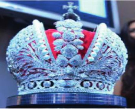
2 Computational Intelligence and Neuroscience

 The paper is organized as follows. After reviewing some such as normals of the boundary vertices to determine
related work in Section 2, the main types and characteristics optimal vertices, so as to adjust the position of the pre-
of annular holes are studied and an intelligent identification repaired hole triangular surface patch. However, for com-
method for annular holes is proposed in Section 3. In Section plex holes, especially for the hole boundary area with large
4, an improved implicit surface repair method for annular curvature variation, the geometric features of the original
holes based on Radial Basis Function (RBF) is presented. In model would be lost, and the repair result would be too flat.
Section 5, compared with the results of internationally well- The hole-filling algorithm based on implicit surface
known commercial software and a traditional hole repair fitting repairs holes with an implicit surface established with
method, experimental results and discussion are given. Fi- original model data. Lévy [18] parametrized the entire model
nally, our summary, evaluation, and direction for further data to the plane for processing, and the algorithm is less
research are discussed in Section 6. efficient when the area of the repaired holes is small. and the
 number of triangles is large. Brunton et al. [19] first flattened
2. Related Work the hole boundaries without self-intersection onto the ref-
 erence plane for filling and then used the minimum energy
Originating as early as the 1980s, 3D printing has boomed method to embed the patched mesh back into the spatial
again with the promotion of the Internet since 2010. Having mesh. Fortes et al. [20] proposed a shape feature determi-
made positive progress on the market application in fields nation method on top of Brunton’s. Based on the mini-
including aerospace, automotive, and healthcare, it got mization of an energy function, the holes were filled by
started in 3D printed cars, airplanes, and artificial liver inheriting the local information of the holes in the original
tissues. It can be seen that 3D printing is continuing to model. The method required better local data quality of
promote and expand its application. In 2012, the British holes. Du et al. [21–25] all used RBF to fit the implicit surface
Magazine the Economist evaluated 3D printing as “an im- of holes and then adjusted new vertices to the implicit
portant symbol of the third industrial revolution,” which surface. The method was suitable for repairing simple holes
would become a new creative technology to change the and island holes. For island holes with large curvature
future world [6]. Since then, 3D printing has also gained the variation, a bridging method was proposed to connect the
attention of the average consumer. In October 2013, the island boundary and hole boundary. Zhao et al. [26] carried
world’s first successful auction of a 3D printed artwork out a preliminary repair with the advancing front method
named “ONO God” was held [7]. 3D printed shoes, jewelry, and then finished the repair by solving Poisson equation to
dolls, and other products have also gradually entered the adjust positions of added vertices. This method was not
vision of ordinary consumers, as shown in Figure 1. applicable to the repair of large holes.
 Along with the wide application of 3D printing, many Through the above analysis on hole-filling techniques, it
scholars at home and abroad have researched the rapid is proved that the mesh growth-based repair method is a
reconstruction and repair of 3D printed models. The simple simple idea, easy to implement, and more effective for
and flexible structure, high stability, and topology of tri- repairing holes in flat areas with simple structures and no
angular mesh models lead to the rapid and mature devel- significant features. The implicit surface fitting method
opment of the hole-filling technique based on triangular produces a smoother repair surface, inherits the original
mesh models [11]. A more typical repair method is the mesh data information during the repair process, and has
surface-based hole-filling algorithm, which repairs holes on little interference with the original mesh model and more
the surface with the help of data near the holes by directly accurate repair results. However, it asks for a harsher sce-
detecting and identifying the hole information of the input nario and would always smooth sharp features. Both
3D model. It mainly includes the mesh growth method based methods can obtain ideal results for simple holes, but there
on adding new sampling points and the method based on may be mapping failure or mapping error for complex holes,
implicit surface fitting [12–14]. resulting in poor hole-filling effects.
 The mesh growth method based on adding new sampling For the segmentation and repair of complex holes, Jun
points generates new sampling points from hole triangle [27] proposed an algorithm to split a complex hole into
boundaries to hole area and constructs new triangular simple holes and then fill each divided simple hole, which
patches by edge swapping and triangle refining until the helped in triangulating and repairing holes with self-inter-
whole hole is covered. Pernot et al. [15] proposed the secting boundaries in the projection process but was not
curvature minimization principle to repair holes by adding ideal in filling complex holes of other types, especially the
new triangles under the premise of minimizing the curvature problem of self-intersecting boundaries in the nonprojection
variation between the surrounding and inserted meshes, process. Inspired by this method, Li et al. [28] presented an
which is applicable to holes with a simple shape. March- algorithm based on the concept of edge expansion to split
andise et al. [16] used the hole boundary points as well as the complex holes into simple holes and then perform hole-
neighboring vertices as the basis for establishing surface filling with due consideration of the neighboring mesh
patches and sampling on the surface patches. The method morphology. Lai and Hsu [29] further considered the
had a relatively high hole-filling accuracy, but it was not treatment of island holes and proposed a hole-filling algo-
applicable to the case where the curvature variation of the rithm based on B-sample surfaces to fit the vertices near the
hole area was large. Wang et al. [17] first repaired the hole holes to the B-sample surfaces, emphasizing the topological
with the advancing front method and then used the data accuracy and smoothness of the joint between the new mesh
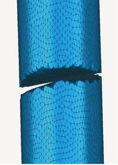
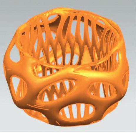
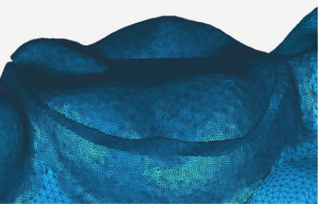
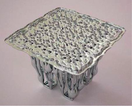
Computational Intelligence and Neuroscience 3

 (a) (b) (c) (d)

 (e) (f )

Figure 1: 3D printed consumer goods [8–10]. (a) 3D printed shoes STRVCT. (b) Nike 3D printed football shoes. (c) Faux Russian big
crown. (d) 3D printed table. (e) Custom doll. (f ) Flower lampstand.

and the existing mesh. Feng et al. [30] introduced a fast products, there are many narrow features, surface bulges,
filling method for triangular meshes based on hole size, hollow-carved structures, or folds, as shown in Figure 2.
which classified holes into small-sized, middle-sized, and They can easily cause fracture, local loss, or separation of the
large-sized holes according to their size and used different triangular mesh model during model construction, scan-
filling algorithms for different hole types. However, the ning, and acquisition. So, a specific type of hole always
classification method, which only considered the hole size occurs, namely, an annular hole. Using the existing repair
and ignored the complex topological morphology, would methods, it is easy to cause the fillings of hollow-carved
hardly achieve satisfactory results in filling complex holes. structures or folds, and they lead to high differences from the
Wen et al. [31] presented a surface-repairing method with original structure. In addition, most users for consumer
automatic identification of defective holes and maintenance goods are ordinary people lacking the ability to operate
of detail features in the hole region, but the method was only specialist repair software, so the result of hole repair is not
applicable to repair defective holes in simply connected satisfactory.
domains, ignoring the topology of complex missing regions.
By analyzing the hole boundaries and topology, Li [12]
 3.2. Annular Holes. The annular hole is formed by two
classified holes into ordinary holes, interstitial voids, island
 boundary lines with similar shape and no common point,
holes, and semiclosed holes and proposed a hole-filling
 whose positional relationship is approximate coplanar or
algorithm based on Poisson equation, which can repair
 parallel, as shown in Figure 3. Annular holes are commonly
large-scale complex 3D models containing a large number of
 found in sections, cross-sections, or folds of models. Two
holes and a variety of hole types. The method was applied to
 types of annular holes are summarized through analysis.
the restoration of heritage models with slightly insufficient
 Coplanar annular hole: the positions of two annular
repair efficiency. Centin et al. [32] proposed a Poisson-
 closed curves are approximately coplanar, and the normal
driven approach, which allowed to close complex holes,
 directions are similar, as shown in Figure 3(a). It is a
islands, gaps, and missing parts with a seamless integration
 common type of annular holes occurred in the surface bulges
of the patching triangles along the mesh boundaries, with
 or hollow-carved structures.
guaranteed and homogeneous mesh quality. But its repair
 Parallel annular hole: the positions of two annular closed
quality was seriously influenced by the boundary curves user
 curves are approximately parallel, and the normal directions
selected. Based on the above analysis, the intelligent iden-
 are nearly contrary, as shown in Figure 3(b). It is an un-
tification and repair method for annular holes is still a
 common type of annular holes occurred in narrow features,
challenge.
 hole features, and folds. There are few repair methods to deal
 with such holes.
3. Annular Holes and Their Intelligent The annular hole has two annular closed curves. The
 Identification Method application of simple hole filling methods to an annular hole
 will repair all the interior of the two annular closed curves,
3.1. Generation of Annular Holes. In the consumer goods resulting in a large number of self-intersecting patches. As
field, due to the complex and varied structures of most for island hole repair methods, the number of internal
products such as handicrafts, doll models, and bionic triangular surface patches of annular holes is too large, and
4 Computational Intelligence and Neuroscience

 Figure 2: The example products prone to annular holes.

 (a) (b)

 Figure 3: Two types of annular holes. (a) Coplanar annular hole. (b) Parallel annular hole.

the hole normal directions of parallel annular holes are We set the hole boundary points as P1, P2, P3, . . ., Pn, and
nearly contrary. So, it is not appropriate to simply use the O as the gravity center of hole boundary points, i.e.,
surface deformation repair method of deleting island frag- 1 n
ments or selecting some islands as constraint points, which is O(X, Y, Z) � Pi , i � 1, 2, . . . , n. (1)
 n i�1
easy to affect the repair quality or destroy the original
structure of the model. For this reason, the repair of annular Using the coordinates of the hole boundary points and
holes needs to be treated separately. the gravity center O, a 3 × 3 covariance matrix C can be
 defined as
3.3. Intelligent Identification Method for Annular Holes. cov(X, X) cov(X, Y) cov(X, Z)
 ⎡⎢⎢⎢ ⎤⎥⎥⎥
As the annular hole is made up of two boundaries that are C � ⎢⎢⎢⎣ cov(Y, X) cov(Y, Y) cov(Y, Z) ⎥⎥⎥⎥⎦,
 ⎢ (2)
similarly located and shaped, the hole connects two dis-
 cov(Z, X) cov(Z, Y) cov(Z, Z)
continuous triangular mesh sections of the model. The two
boundaries of the annular hole can be identified by detecting where
the distance between the boundaries of different combina- ni�1 Xi − X Yi − Y
tions of triangular facets; that is, an annular hole is com- cov(X, Y) � . (3)
 n−1
posed of the free boundaries of two sets of triangular meshes.
Therefore, the following determination method for annular The eigenvalues and eigenvectors of the matrix can
holes is presented. be calculated through Jacobi method. We set the three
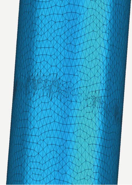
Computational Intelligence and Neuroscience 5

 �→
eigenvalues as the first vector V1 and the eigenvector cor-
 Start
responding
�→ to the smallest eigenvalue as the second vector
V2 . The eigenvalues and eigenvectors of the Jacobi matrix
represent the distribution direction of the points, and the
 Model preprocessing
main feature that distinguishes an annular hole from an
island hole is the approximation of the distribution pattern
of the points between two boundaries. Therefore, the
 Calculate all the closed hole
characteristic distance between two boundaries of the an- boundaries
nular hole is defined as
 ��→ ��→ ��→ ��→
 Disab � Va1 × Vb1 + Va2 × Vb2 . (4)
 Judge whether Yes
 In this equation, a and b represent the two boundaries of the number of boundarIes is less
 than 2
an annular hole. Disab is the characteristic distance between
 ��→ ��→
boundaries a and b. Va1 and Vb1 are the first vectors of No
 ��→ ��→
boundaries a and b. Va2 and Vb2 are the second vectors of
boundaries a and b. Then, we screen a large number of Calculate the nearest boundary of
 each boundary
annular holes and island holes and calculate their charac-
teristic distances. An empirical value of the characteristic
distance is found to distinguish an annular hole from an
island hole. When Disab < 0.15, an annular hole is formed Whether they are
 No
between the two boundaries. At this point, the corre- mutually nearest boundaries, and
sponding repair method can be used to achieve optimal Disab< 0.15?
results. Accordingly, an intelligent identification process for
annular holes is planned as in Figure 4. Yes
 Annular hole No annular hole
Step 1. Model preprocessing. Segment all the complex holes
to single holes without common points.

Step 2. Calculate all the closed hole boundaries, and exclude
crack holes and dislocation holes. The method in Steps 1 and End
2 has been researched in another thesis [33].
 Figure 4: Intelligent identification process for annular holes.
Step 3. Judge whether the number of closed boundaries is
less than 2. If yes, this indicates that there is no annular hole,
and it ends; if no, proceed to next step.

Step 4. Calculate the nearest boundary of each boundary. It
is measured by the distance between the nearest points
between two boundaries.

Step 5. Judge whether they are mutually nearest boundaries,
and the boundary feature distance is less than 0.15. Mutual
nearest boundary means that the nearest boundary of
boundary a is b, and the nearest boundary of boundary b is a.
At the same time, in order to eliminate the case that two
 Figure 5: Example of adjacent simple holes.
simple holes are adjacent (as shown in Figure 5), it is also
necessary to meet the following conditions: on the fitting
plane of the boundary, the gravity center of boundary a is
within b, and the gravity center of boundary b is within a. If annular hole has two boundaries and two sets of corre-
the above conditions are met, it is an annular hole. Oth- sponding cutting and stitching boundaries, with narrow or
erwise, there is no annular hole. flat hole lines and massive boundary points. Using tradi-
 tional hole-filling methods, it always has low repair efficiency
Step 6. End. and a high failure rate. Besides, various consumer products
 lead to a variety of annular holes, and the systematicness
4. Repair Method for Annular Holes and robustness of the above method are also insufficient.
 Therefore, we propose a method that stitches and fills the
Traditional hole-filling methods generally require a process holes, optimizes the triangulation, constructs implicit sur-
of surface fitting, surface cutting, and surface stitching. The face, and finally carries out surface integral deformation. The
6 Computational Intelligence and Neuroscience

method can solve the repair issue of diversified annular holes
and extend the application range in consumer products. Q0 Q1 Q2 Q3 Q4
 L1

4.1. Hole Boundary Stitching and Filling. First of all, an initial
stitching surface patch is constructed as the basis for surface L0
fitting. In this paper, the method of connecting the nearest P0 P1 P2 P3
points is used to stitch annular holes, as shown in Figure 6.
The specific steps are described as follows.
 Figure 6: Stitch annular hole boundaries.

Step 1. Reorient hole lines. As the two types of annular holes
have different hole line directions, the two hole lines of an
annular hole need to be adjusted to the same direction. The
same direction refers to the fact that, on the best-fit plane of A A
the two hole lines, the polygons formed by the projection of D D
the hole lines are all clockwise or counterclockwise. Herein,
the counterclockwise direction is taken as positive.
 B B
Step 2. Connect initial triangles. Start from the starting C C
point P0 of the hole line L0 with fewer points, calculate the
nearest point Q0 of P0 on the other hole line L1 , and connect Figure 7: Illustration of the edge-swap method.
P0 and Q0 . Find the next point Q1 of L1 and its nearest point
Q2 on L1 , and connect P1 and Q2 . Triangulate the area
composed of P0 -P1 -Q2 -Q0 to obtain triangles P0 Q1 Q0 ,
P0 P1 Q1 , and P1 Q2 Q1 . neighboring points, depending on the size of the hole) to
 build a collection V � Pi , i � 1, 2, . . . , n (n is the number of
Step 3. Connect the remaining triangles. Repeat the above hole boundary vertices and neighboring points) of inter-
steps for the points on L0 until all boundary points on L0 are polation constraint points. The interpolation constraint
calculated. points on the surface satisfy
 f Pi � 0, i � 1, 2, . . . , n. (5)
4.2. Triangulation Optimization. Before the surface is fitted,
the stitched triangle patches need to be refined, so that it can In order to avoid useless solutions of f ≡ 0, while
be smoothly connected to the original model. The specific keeping the positions of the boundary points of stitched
optimization principle and method are as follows: (1) for a patches unchanged, we calculate the normal information of
triangular patch with an area larger than the specified area, the refined mesh model boundaries and add additional
divide the patch into three triangular patches by taking a constraint points in the normal direction. They are located in
point at the center of the triangle and connecting that point the inner or outer directions of the surface. The additional
to its three vertices. (2) If two triangles are connected by an constraint points should satisfy
edge, and one triangle is inside the circumscribed circle of f Pi + h i N i � h i , (6)
the other triangle, the edge is called a long and narrow edge.
The edge-swap method should be used for optimization. where Ni is the normal vector of the surface located at the
Edge-swap is achieved by swapping the diagonals of the vertex Pi , and hi is a normal constraint value with a small
convex quadrilateral formed by two adjacent triangles, so positive value. It can be assumed that all additional con-
that the narrow triangle converges to a positive triangle, as straint points are located at the same distance from the
shown in Figure 7. surface, and they are on an equivalent surface to the hole
 surface. The value of the constraint does not affect the so-
4.3. Implicit Surface Construction. The initial repair surface lution of the implicit equation for the hole surface, so the
has been created by stitch and refined triangulation of the implicit equation for the hole surface can be taken to have a
two hole lines of the annular hole, but it is not yet smoothly value of hi � 1 at all additional constraint points.
integrated with the whole surface. For that, the RBF is used From this, we combine all interpolated constraint points
to establish an implicit surface equation for annular holes, to and additional constraint points to create a set of constraint
ensure as much continuity and smoothness as possible points V � Pi , i � 1, 2, . . . , N (N is the number of all the
between the repaired surface and the original surface. hole constraint points) and form the following constraint:
 Firstly, to ensure a smooth and continuous joint between f Pi � h i , i � 1, 2, . . . , N. (7)
the hole boundary and its surrounding original triangular
surface, we use the vertex of the two boundaries of an From the constraint points, we can define the implicit
annular hole and the multiplet neighboring points of its surface equation f(r) � 0. The energy function [22, 34] for a
neighboring triangular patches (typically 3–5 multiplet thin plate with its second-order differentiable function is
Computational Intelligence and Neuroscience 7

 z2 f z2 f z2 f z2 f interpolation function f(r), and the implicit surface
 E� 2 + 2 + 2 +2 equation for the hole established by the RBF can be given as
 R3 zx zy zz zxzy
 (8) n
 ��������������������������� 3
 2 y 2 2
 z2 f z2 f f(x, y, z) � wj x − Pxj + y − Pj + z − Pzj
 +2 +2 dxdydz.
 zxzz zyzz j�1
 + q0 + q1 x + q2 y + q3 z � 0. (12)
 This energy function reflects the smoothness of the
function f in three dimensions, and it has lower energy
values in regions of the surface where there are no sharp
changes in curvature such as folds. The interpolation 4.4. Surface Integral Deformation. Once the implicit equa-
function is solved under the interpolation constraint of tion for the annular hole surface has been established, the
f(Pi ) � hi such that the value of the energy function is vertices of triangular patches from the triangulation opti-
minimized. At this point, the form of the interpolation mization in 4.2 need to be adjusted to the fitted implicit
function f is obtained as the RBF form [13]: surface, that is, integral deformation of the surface. In this
 paper, the classical gradient descent method is used to adjust
 N the vertices of triangular patches after triangulation, where
 f(r) � wj ϕ r − Pj + Q(r). (9) all the repaired vertices of triangular patches are gradually
 j�1 approximated towards the implicit surface along the gra-
 dient direction of the implicit equation f(x, y, z), until they
 In this equation, r denotes any point on the generated are adjusted to the fitted hole implicit surface within the
surface, r � (x, y, z); Pj denotes the points defining the allowed error range.
 y
equation, Pj � (Pxj , Pj , Pzj ); wj denotes the real weight Gradient descent is an iterative optimization-seeking
corresponding to each constraint point; Q(r) is a first order algorithm for some criterion function. Let f(r) be some
polynomial. For any point r, the form of Q(r) is criterion function and r a vector, and then the negative
Q(r) � q0 + q1 x + q2 y + q3 z, where q0 , q1 , q2 and q3 are real gradient direction of r is the direction, where f(r) decreases
coefficients of the polynomial. ϕ(r − Pj ) is the RBF. In three- fastest, along which the approximation point can be reached
dimensional space, as functions with three variables need to fastest [35]. The gradient of the implicit function f(x, y, z) is
be fitted, the more effective form of RBF is a triharmonic denoted as ∇f � (zf/zx, zf/zy, zf/zz) [22]. From the
spline function ϕ(r) � r3 . implicit surface equation for holes, we get
 In order to solve for the weights and polynomial coef-
ficients, each constraint point must satisfy both the inter- N
 �������������������������
 zf 2 y 2 2
polation constraint and the orthogonality conditions. � 3 wj x − Pj x − Pxj + y − Pj + z − Pzj + q1 ,
 x
 zx j�1
 N
 f Pi � wj ϕ Pi − Pj + Q Pi , N
 �������������������������
 zf y 2 y 2 2
 j�1 � 3 wj y − Pj x − Pxj + y − Pj + z − Pzj + q2 ,
 (10) zy j�1
 N N N N
 y
 wj � wj Pxj � w j Pj � wj Pzj � 0. �������������������������
 N
 j�1 j�1 j�1 j�1 zf 2 y 2 2
 � 3 wj z − Pj x − Pxj + y − Pj + z − Pzj + q3 .
 z

 Let ϕij � ϕ(Pi − Pj ). From the above conditions, we zz j�1
obtain the following set of linear equations: (13)
 y
 ϕ ϕ12 · · · ϕ1n 1 px1 p1 pz1 w1 h1 Depending on the vertex of each triangulated patch, the
 ⎡⎢⎢⎢ 11 ⎥⎤⎥⎥⎡⎢⎢⎢ ⎤⎥⎥⎥ ⎡⎢⎢⎢ ⎤⎥⎥⎥
 ⎢⎢⎢ ϕ ϕ22 · · · ϕ2n 1 px2
 y
 p2 pz2 ⎥⎥⎥⎢⎢⎢ w2 ⎥⎥⎥ ⎢⎢ h2 ⎥⎥⎥ ⎢ new position to which it is adjusted needs to be calculated.
 ⎢⎢⎢ 21 ⎥⎥⎥⎢⎢⎢ ⎥⎥⎥ ⎢⎢⎢ ⎥⎥⎥
 ⎢⎢⎢ ⎥⎢ ⎥ ⎢⎢ ⎥ Considering the iteration efficiency and the optimization
 ⎢⎢ ⋮
 ⎢⎢⎢ ⋮ ⋱ ⋮ ⋮ ⋮ ⋮ ⋮ ⎥⎥⎥⎥⎢⎢⎢⎢⎢ ⋮ ⎥⎥⎥⎥⎥ ⎢⎢⎢⎢ ⋮ ⎥⎥⎥⎥⎥ effect, we chose the following equation as the iteration
 ⎢⎢⎢ ⎥⎥⎥⎢⎢⎢ ⎥⎥⎥ ⎢⎢⎢ ⎥⎥⎥
 pzN ⎥⎥⎥⎥⎥⎢⎢⎢⎢⎢ wN ⎥⎥⎥⎥⎥ ⎢⎢⎢⎢⎢ hN ⎥⎥⎥⎥⎥
 y
 ⎢⎢⎢ ϕN1 ϕN2 · · · ϕNN 1 pxN pN formula:
 ⎢⎢⎢ ⎥⎥⎥⎢⎢⎢ ⎥⎥⎥ � ⎢⎢⎢ ⎥⎥⎥.
 ⎢⎢⎢ 1
 ⎢⎢⎢ 1 ··· 1 0 0 ··· 0 ⎥⎥⎥⎥⎢⎢⎢⎢⎢ q0 ⎥⎥⎥⎥⎥ ⎢⎢⎢⎢⎢ 0 ⎥⎥⎥⎥⎥ f rk
 ⎢⎢⎢ x ⎥⎥⎥⎢⎢
 ⎢ ⎥⎥⎥ ⎢⎢⎢ ⎥⎥⎥ rk+1 � rk − ��� ��∇f rk , (14)
 ⎢⎢⎢ p1 px2 ··· pxN 0 0 ··· 0 ⎥⎥⎥⎥⎢⎢⎢⎢⎢ q1 ⎥⎥⎥⎥ ⎢⎢⎢⎢⎢ 0 ⎥⎥⎥⎥ ��∇f rk 2 ���
 ⎢⎢⎢ ⎥⎥⎥⎢⎢ ⎥⎥⎥ ⎢⎢ ⎥⎥⎥
 ⎢⎢⎢ y ⎢ ⎥ ⎢ ⎥
 0 ⎥⎥⎥⎥⎥⎦⎢⎢⎢⎢⎣ q2 ⎥⎥⎥⎥⎦ ⎢⎢⎢⎢⎣ 0 ⎥⎥⎥⎥⎦
 y y
 ⎢⎢⎣ p1 p2 ··· pN 0 0 ··· where k denotes the number of iterations. Calculate the
 pz1 pz2 ··· pzN 0 0 ··· 0 q3 0 difference rk+1 − rk between the new position of the vertex
 (11) and the position before stretching. If rk+1 − rk ≤ ε (ε is a given
 limited error), it can be considered that the new position of
 For the annular hole repair surface, as the constraint the vertex rk+1 is on the hole surface and the iteration ends.
points taken are data points around the hole boundary, the Otherwise, rk+1 replaces rk and the iteration continues.
solution time is shorter with the Gauss elimination method, The implicit surface equation of the hole describes the
and a unique set of solutions (w1 , w2 , . . . wN , q0 , q1 , q2 , q3 ) surface formed by the hole boundaries and their multiplet
can be obtained directly. Bring the obtained results into the neighboring triangular patches, so the vertices of the
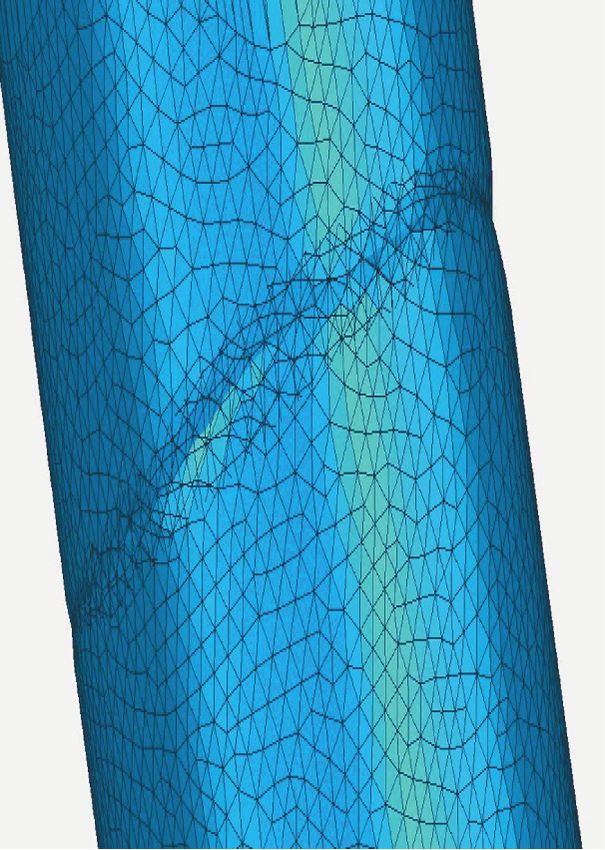
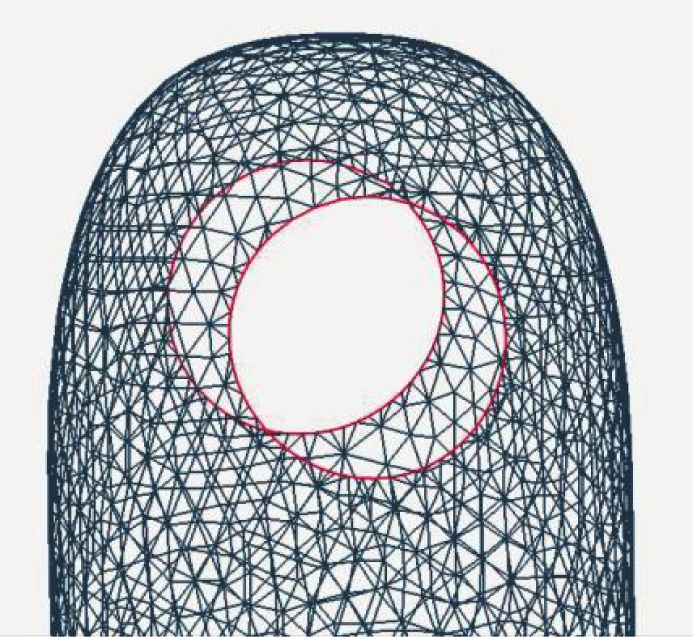
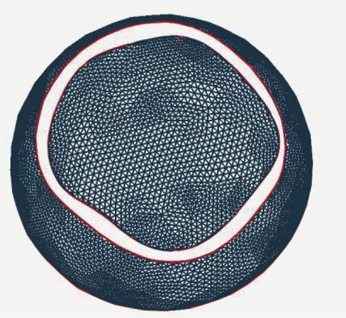
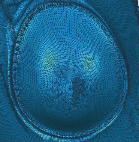
8 Computational Intelligence and Neuroscience

 (a) (b) (c) (d)

 (e)

Figure 8: Comparison of repair effect of shoe model. (a) Original annular hole model. (b) Repair result of Geomagic. (c) Repair details of
Geomagic. (d) Repair results of the proposed method in this paper. (e) Repair details of the proposed method in this paper.

adjusted triangles are located on the same surface as the Figure 8(d). The repair details are displayed in Figure 8(e). It
vertices of the triangular patches around the hole boundary. can be seen that triangular meshes are evenly divided, and
It is ensured that the repaired hole surface is well stitched to the surface fitted between the two separated surfaces is
the original triangular mesh surface and maintains a con- smooth.
sistent surface form and continuity. Figure 9 shows the comparison of repair effect of bone
 model. An annular hole exists at the fracture location of the
5. Experimental Results and Discussion bone, as shown in Figure 9(a), and the annular hole lines are
 also indicated by red lines. Geomagic repairs the broken
As few scholars have researched automatic identification holes, respectively, resulting in the formation of two inde-
and repair methods for annular holes, it is difficult to find a pendent parts, as Figures 9(b) and 9(c) depict. With the
targeted algorithm for comparison. For this reason, this proposed method, the annular hole of the bone model is
paper selects and compares the repair results with the well- accurately identified and repaired, leading to regular tri-
known commercial software Geomagic and a traditional angular meshes and smooth surfaces, as shown in
hole repair method to determine the identification and Figures 9(d) and 9(e).
repair effect of the research method. All the developed al- When repairing the annular hole on the tooth surface,
gorithms were implemented in C++ by using Visual Studio the result is similar to the shoe and bone models, as shown in
2013 and tested on a PC equipped with an Intel Core i7-
4790 processor and 8 GB of RAM on Windows 10. In the
 ® Figure 10. Through the above cases, we can draw the fol-
 lowing conclusions. Geomagic cannot automatically identify
comparison process, three types of consumer-oriented annular holes. Without human intervention, the software
models are selected, such as shoe, bone, and tooth, because fills the inside of two closed hole boundaries, leading to
these models are prone to the presence of annular holes. discrepancies between the restoration and the actual re-
 Figure 8 compares the repair effect of shoe model be- quirements, and even to the separation of the model.
tween Geomagic and the proposed method. Figure 8(a) Geomagic destroys the original structure of the model. With
shows that an annular hole exists at the folding location the proposed method, annular holes in the model are all
of the shoe mouth, and the annular hole lines are indicated accurately identified and repaired between the hole
by red lines. When using Geomagic to repair, the two hole boundaries. As can be observed through the detailed graphs,
lines of the shoe model are repaired, respectively, resulting in the structures of the repaired model match the original
the closure of the shoe mouth, and the repaired surface models, and the triangular mesh density, the continuity with
differs greatly from that of the original model, shown in the edge meshes, and the smoothness are all ideal.
Figures 8(b) and 8(c). With the proposed method, the an- After repairing by the proposed method and Geomagic,
nular hole of the shoe model is accurately identified and the three repaired models were checked by a grid doctor. In
repaired between the hole boundaries, as shown in terms of the six types of repair defects including nonmanifold
Computational Intelligence and Neuroscience 9

 (a) (b) (c) (d)

 (e)

Figure 9: Comparison of repair effect of bone model. (a) Original annular hole model. (b) Repair result of Geomagic. (c) Repair details of
Geomagic. (d) Repair results of the proposed method in this paper. (e) Repair details of the proposed method in this paper.

 (a) (b) (c) (d)

 (e)

Figure 10: Comparison of repair effect of tooth model. (a) Original annular hole model. (b) Repair result of Geomagic. (c) Repair details of
Geomagic. (d) Repair results of the proposed method in this paper. (e) Repair details of the proposed method in this paper.

edges, self-intersections, highly-creased edges, spikes, small method has fewer defects and higher repair quality. The
components, and small holes, Geomagic is found to have repair time of our method is equivalent to Geomagic, so the
more defects like spikes, highly creased edges, and self-in- repair efficiency is acceptable. Specific comparison infor-
tersections, while the model repaired by the proposed mation is shown in Table 1.
10 Computational Intelligence and Neuroscience

 Table 1: Comparison of repair results after inspection.
 Nonmanifold Self- Highly creased Small Small Repair time
Objects Methods Spikes
 edges intersections edges components holes (s)
 Geomagic 0 102 503 453 0 0 0.077
Shoe Method in this
 0 11 39 136 0 0 0.086
 paper
 Geomagic 0 0 0 357 0 0 0.056
Bone Method in this
 0 0 0 0 0 0 0.062
 paper
 Geomagic 0 90 62 1398 0 0 0.046
Tooth Method in this
 0 8 48 479 0 0 0.058
 paper

 (a) (b)

Figure 11: Repair result of bone model with the method proposed by Centin. (a) The overall repair result of bone model with the method
proposed by Centin. (b) Repair details of bone model with the method proposed by Centin.

 The existing repair methods, when applied to the repair of holes into ordinary holes. The result and quality are affected
annular holes, mostly require manual involvement. Taking by the skills of technicians, and the efficiency is drastically
the algorithms proposed by Centin [32] as an example, the reduced, which also makes the operation difficult for average
user input for their method must be a set of boundary curves consumer users. Therefore, the above comparison shows that
without defects, and holes or gaps, which are not selected the proposed method can automatically determine whether
should not be filled. So, the repair quality is seriously affected two closed hole boundary lines form an annular hole by their
by the input boundaries. For the bone model, we selected shape and distance relationships and provide intelligent re-
boundaries with slight defects to repair. An obvious dent pair methods of stitching and filling, triangulation optimi-
defect appeared, as shown in Figure 11(a). With their re- zation, and surface integral deformation. The method can
stricted Delaunay triangulation and tailoring routine, there is meet the repair needs of various types of consumer-oriented
a high quality mesh in the repair area, as shown in models, reduce the operational difficulties of nonspecialist
Figure 11(b). But the repair time was significantly increased technicians, and improve repair efficiency.
to 1.278 s without considering time spent on the manual
selection of boundary lines, and our time was 0.062 s with the 6. Conclusion
automatic identification of boundary lines. Therefore, our
method has the advantage of high repair efficiency. In the field of consumer goods such as handicrafts and
 In summary, as repair algorithms or software like Geo- bionic products, narrow features, surface bulges, and folds
magic cannot independently identify and process annular can easily lead to annular holes in the triangular mesh model
holes, manual repair method is needed. The use of manual during the process of construction, scanning, and acquisi-
repair requires the selection of two closed hole boundary tion. However, the traditional repair method for common
curves, complex manual bridging, and splitting of annular holes is unsuitable for annular holes, which would cause
Computational Intelligence and Neuroscience 11

defects such as self-intersecting patches, or even alteration of References
the original structure of the model.
 To this end, we propose an intelligent identification and [1] M. H. Ali, S. Batai, and D. Sarbassov, “3D printing: a critical
repair algorithm for annular holes. From the structural review of current development and future prospects,” Rapid
 Prototyping Journal, vol. 25, no. 6, pp. 1108–1126, 2019.
characteristics of the annular hole, we give the definition and
 [2] I. Karakurt and L. Lin, “3D printing technologies: techniques,
the automatic identification method for annular holes
 materials, and post-processing,” Current Opinion in Chemical
through analysis of the shape and position relationships Engineering, vol. 28, pp. 134–143, 2020.
between the two closed hole lines. Referring to the tradi- [3] Rahito, D. Wahab, and A. Azman, “Additive manufacturing
tional implicit surface repair method of single hole, we for repair and restoration in remanufacturing: an overview
propose a new improved method. In order to optimize the from object design and systems perspectives,” Processes, vol. 7,
systematicness and robustness of the repair method, we first no. 11, p. 802, 2019.
stitch and fill the two annular hole lines, then optimize [4] shapeways, “3D printing service,” 2021, https://www.
triangulation, construct a variational implicit surface based shapeways.com/business/3d-printing-services.
on RBF, and finally deform the surface integrally based on [5] “3D printing innovation and creativity platform,” 2021, http://
gradient descent. The proposed method achieves a smooth tmxk3d.com/.
joint of the repaired hole surface with the original triangular [6] T. Economist, “The third industrial revolution,” Economist,
mesh surface, and the repaired surface is smooth and ac- vol. 21, pp. 3–16, 2012.
curate. Finally, we verify the feasibility of the method by [7] H. Zhang, “Preface to the selection plan “customized cultural
examples, proving that it can replace the manual repair and creative design services for 3D printing”,” Packaging
 Engineering, vol. 40, p. 1, 2019.
methods and significantly improve the repair quality and
 [8] F. Yu, “3D printing, “customize” the life,” China Public Sci-
efficiency.
 ence, vol. 6, pp. 23–25, 2014.
 There are two important improvements in our method. [9] Y. Zou, “The various forms of arbitrary objects converging” --
Firstly, it retains all the facet information in the annular hole innovation research of 3d printing technology in the interior
and stitches the facet between two closed hole lines, instead design,” Master Degree Thesis, Hunan Normal University,
of filling a single hole boundary in sequence or using the Changsha, China, 2016.
artificial bridging repair method of technicians. The repair [10] G. A. Rundle, Revolution in the Making: 3D Printing, Robots
quality is also ensured. Secondly, the routine of stitching and and the Future, pp. 26–58, Machinery Industry Press, Beijing,
filling, triangulation optimization, and surface integral de- China, 2015.
formation has higher repair efficiency. Especially for parallel [11] M. Attene, M. Campen, and L. Kobbelt, “Polygon mesh
annular holes, it avoids possible stitching errors caused by repairing: an application perspective,” ACM Computing
the inconsistent normal vectors of holes. But the errors Surveys, vol. 45, pp. 3472–3476, 2013.
always appear in other repair methods or software. [12] Y. Li, Research on hole-filling algorithm on meshes for digi-
 In the repair process, the implicit surface repair method talization of cultural relic, Northwest University, Xian, China,
based on RBF can obtain smoother repair surfaces, but it also 2017.
 [13] G. Turk and J. F. O’Brien, “Modelling with implicit surfaces
smooths out sharp features. In the future, we will provide
 that interpolate,” ACM Transactions on Graphics, vol. 21,
corresponding repair methods for more special features. The
 no. 4, pp. 855–873, 2002.
narrow features, surface bulges, hollow-carved structures, or [14] X. G. Jin, H. Q. Sun, and Q. S. Peng, “Subdivision interpo-
folds occurring in consumer products will be identified and lating implicit surfaces,” Computers & Graphics, vol. 27,
repaired more accurately. When the method is applied to the pp. 763–772, 2003.
repair of 3D printed models in the consumer goods field, it [15] J.-P. Pernot, G. Moraru, and P. Véron, “Filling holes in
will not require the participation of technicians. The easy meshes using a mechanical model to simulate the curvature
operation characteristics of the method will attract the at- variation minimization,” Computers & Graphics, vol. 30, no. 6,
tention and attempt of a large number of consumers. It will pp. 892–902, 2006.
promote the widespread use of 3D printing technology. [16] E. Marchandise, C. Piret, J. F. Remacle, and J.-F. Remacle,
 “CAD and mesh repair with radial basis functions,” Journal of
 Computational Physics, vol. 231, no. 5, pp. 2376–2387, 2012.
Data Availability [17] X. C. Wang, J. J. Cao, X. P. Liu, and B. J. Li, “Advancing front
The data used to support the findings of this study are in- method in triangular meshes hole-filling application,” Journal
cluded within the article. of Computer-Aided Design & Computer Graphics, vol. 23,
 pp. 1048–1054, 2011.
 [18] B. Lévy, “Dual domain extrapolation,” ACM Transactions on
Conflicts of Interest Graphics, vol. 22, pp. 364–369, 2003.
 [19] A. Brunton, S. Wuhrer, C. Shu, P. Bose, and E. D. Demaine,
The authors declare that there are no conflicts of interest “Filling holes in triangular meshes by curve unfolding,” in
regarding the publication of this paper. Proceedings of the IEEE International Conference on Shape
 Modeling and Applications, pp. 26–28, Beijing, China, June
Acknowledgments 2009.
 [20] M. A. Fortes, P. González, A. Palomares, and M. Pasadas,
This research was funded by the National Key R&D Program “Filling holes with shape preserving conditions,” Mathematics
of China, grant no. 2018YFB1106200. and Computers in Simulation, vol. 118, pp. 198–212, 2015.
12 Computational Intelligence and Neuroscience

[21] J. Du, L. Y. Zhang, H. T. Wang, and S. L. Liu, “Hole repairing
 in triangular meshes based on Radial Basis Function,” Journal
 of Computer-Aided Design & Computer Graphics, vol. 17,
 pp. 1976–1982, 2005.
[22] H. T. Wang, J. Du, S. L. Liu, and L. Y. Zhang, “A novel al-
 gorithm for repairing various holes in mesh surfaces based on
 Radial Basis Function,” Mechanical Science and Technology,
 vol. 24, pp. 744–747, 2005.
[23] J. Morel, A. Bac, and C. Véga, “Surface reconstruction of
 incomplete datasets: a novel Poisson surface approach based
 on CSRBF,” Computers & Graphics, vol. 74, pp. 44–55, 2018.
[24] G. Song, J. Riddle, G. E. Fasshauer, and F. J. Hickernell,
 “Multivariate interpolation with increasingly flat Radial Basis
 Functions of finite smoothness,” Advances in Computational
 Mathematics, vol. 36, no. 3, pp. 485–501, 2012.
[25] S. Liu and C. C. L. Wang, “Quasi-interpolation for surface
 reconstruction from scattered data with radial basis function,”
 Computer Aided Geometric Design, vol. 29, no. 7, pp. 435–447,
 2012.
[26] W. Zhao, S. Gao, and H. Lin, “A robust hole-filling algorithm
 for triangular mesh,” The Visual Computer, vol. 23, no. 12,
 pp. 987–997, 2007.
[27] Y. Jun, “A piecewise hole filling algorithm in reverse engi-
 neering,” Computer-Aided Design, vol. 37, no. 2, pp. 263–270,
 2005.
[28] G. Li, X.-Z. Ye, and S.-Y. Zhang, “An algorithm for filling
 complex holes in reverse engineering,” Engineering with
 Computers, vol. 24, no. 2, pp. 119–125, 2008.
[29] J. Y. Lai and S. H. Hsu, “On the development of a hole filling
 algorithm for triangular meshes,” Journal of the Chinese In-
 stitute of Engineers, vol. 30, no. 5, pp. 877–889, 2007.
[30] C. Feng, J. Liang, M. Ren, G. Qiao, W. Lu, and S. Liu, “A fast
 hole-filling method for triangular mesh in additive repair,”
 Applied Sciences, vol. 10, no. 3, p. 969, 2020.
[31] P. Z. Wen, Y. Q. Lei, and M. L. Sun, “Defective hole iden-
 tification and hole-filling for 3D reconstruction mesh
 models,” Application Research of Computers, vol. 37,
 pp. 1234–1238, 2020.
[32] M. Centin, N. Pezzotti, and A. Signoroni, “Poisson-driven
 seamless completion of triangular meshes,” Computer Aided
 Geometric Design, vol. 35-36, pp. 42–55, 2015.
[33] S. H. Zhang, W. Wu, W. Wei, and J. Bian, “Research on
 partitioning method of complex holes in triangle meshes for
 hole repair,” Electronic Technology and Software Engineering,
 vol. 4, pp. 135–137, 2021.
[34] Q. Wang, “Research and application of triangle mesh models
 transition hole repairing algorithm,” Master Degree Thesis,
 Nanjing University of Aeronautics and Astronautics, Nanjing,
 China, 2007.
[35] T. Karkanis and A. J. Stewart, “Curvature-dependent trian-
 gulation of implicit surfaces,” IEEE Computer Graphics and
 Applications, vol. 21, no. 2, pp. 60–69, 2001.
You can also read