Acta Astronautica - Planetary Sunshade Foundation
←
→
Page content transcription
If your browser does not render page correctly, please read the page content below
Acta Astronautica 186 (2021) 269–279
Contents lists available at ScienceDirect
Acta Astronautica
journal homepage: www.elsevier.com/locate/actaastro
Realistic sunshade system at L1 for global temperature control
Christer Fuglesang *, María García de Herreros Miciano **
KTH Royal Institute of Technology, SE-100 44, Stockholm, Sweden
A R T I C L E I N F O A B S T R A C T
Keywords: So far, space-based geoengineering has rarely been studied from a practical point of view, considered unrealistic
Geoengineering as a near-future alternative to fight climate change. This paper evaluates the feasibility of implementing a space
Space sunshade sunshade in the vicinity of the first Lagrange point of the Sun-Earth system by the middle of the century. The
Solar sail
analysis considers the necessary technological development, the possible trajectories for the shades, and an
Global warming
approximation of the size and cost of the system. It is strongly dependent on the possible optical properties of
future solar sails, so an optimal and a more conservative alternative have been studied. With the latter, the shade
will be formed by 1.5 × 10⁹ sailcraft with a sail area of 2500 m2 and a total mass of 8.3 × 10¹⁰ kg. In the optimal
case, the total mass is 3.4 × 10¹⁰ kg. Each one of these sails will be launched to a 2000 km orbit, from where they
will travel for about 600 days to the equilibrium point using solar radiation pressure. The total cost of the mission
is estimated to be five to ten trillion dollars, based on a launch cost of US$50/kg. There are two main techno
logical challenges for this to become a reality: the low TRL of the solar sails proposed and the necessary
development in the launch vehicle industry given the dimensions of the mission.
1. Introduction conclude that a “laissez faire”-policy is more dangerous than doing too
much [4]. The primary course of action is to significantly reduce the
The global temperature is increasing and with growing certitude this emission of CO2 immediately, and to continue decreasing it until a net
is due to the emission of Green House Gases (GHG), primarily carbon zero-emission is reached sometime around the middle of this century [1,
dioxide (CO2). Human activities are estimated to have caused approxi 5].
mately 1.0 ◦ C of global warming above pre-industrial levels, with a There are doubts, however, that the efforts being made today, as well
likely range of 0.8 ◦ C to 1.2 ◦ C [1]. A recent study shows that each as those planned for the coming decades, to reduce CO2 emissions will be
decade since 1980 has been successively warmer than the preceding enough to prevent large damages to the environment, societies and
one, and that the 2010–19 decadal temperature departure from average economies [5,6]. It is therefore prudent to look into complementary
surpassed the previous record warm decade of 2000–09 by methods to control the Earth’s temperature. Some of these methods are
0.15 ◦ C-0.22 ◦ C [2]. It is certain that a too large and too fast temperature called geoengineering. One way of geoengineering is to limit the amount
increase will have severe social, economic and environmental conse of sunlight reaching the Earth’s surface and thereby limit the tempera
quences, and could even be catastrophic to our civilization. Neverthe ture increase. This can be done by placing sunshades in space, preferably
less, rigorous actions to control the temperature increase will also be in the vicinity of the Lagrange point L1 in the Sun-Earth system. This is a
costly. The complex relationship between temperature increase and less invasive method compared with other techniques, such as putting
economic and social costs is a difficult and debated topic. Two examples aerosols or other reflective particles in the atmosphere, as proposed by
of recent studies are Hänsel et al. “Climate economics support for the UN many, see e.g. Ref. [7] for a discussion and a recent suggestion in
climate targets” [3] and Hassler et al. “The Consequences of Uncer Ref. [8].
tainty: Climate Sensitivity and Economic Sensitivity to the Climate” [4]. The space sunshade concept has been discussed before with various
The former conclude that the temperature increase should be limited to technical solutions [9–17], but it has generally not been considered
a maximum of 2 ◦ C, and preferably 1.5 ◦ C, above pre-industrial values technologically feasible nor economically realistic. A study by Kosugi in
[3], while Hassler et al. show that the uncertainties are very large but 2010, though, found that space sunshades could be cost-effective and
* Corresponding author.
** Corresponding author.
E-mail addresses: cfug@kth.se (C. Fuglesang), mgdhm@kth.se (M.G. de Herreros Miciano).
https://doi.org/10.1016/j.actaastro.2021.04.035
Received 17 December 2020; Received in revised form 19 April 2021; Accepted 27 April 2021
Available online 29 May 2021
0094-5765/© 2021 The Authors. Published by Elsevier Ltd on behalf of IAA. This is an open access article under the CC BY license
(http://creativecommons.org/licenses/by/4.0/).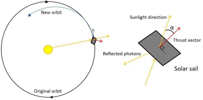
C. Fuglesang and M.G. de Herreros Miciano Acta Astronautica 186 (2021) 269–279
recommended to use them for some hundred years from the latter part of momentum, which transfer a small force to the spacecraft when they
this century [18]. Due to recent technological developments – primarily bounce, i.e. reflect, on it. In the ideal case, the force is always normal to
in the launch vehicles industry, but also by advancements and demon the surface upon which the photon is reflected and pointing away from
strations of solar sailing technology [19] – it is becoming reasonable and the Sun. With a large enough sail in relation to its mass, one can obtain a
viable that a space sunshade system could actually be built fairly soon. force that will dominate the movement of the spacecraft. Such a
In contrast to the earlier proposals that assumed in-space spacecraft will henceforth be referred to as a sailcraft. The direction of
manufacturing, we believe that the most realistic way to construct a the force is controlled by changing the sail attitude in relation to the
sunshade system in the near future is to build the shades on Earth and light flux. For example, as illustrated in Fig. 1, when the sailcraft is
launch them into space. An exception is Angel, who in 2006 [14] sug orbiting the Sun and the SRP force has a component opposite to the
gested a system with small refractive screens manufactured on Earth, direction of the velocity vector, part of the force will work on reducing
but launched with a completely new system based on electromagnetic this velocity, decreasing its orbital energy, and subsequently the
cannons. spacecraft will move closer to the Sun.
In this article, we will present how a sunshade system could be The force from the sunlight - or indeed from the full electro-magnetic
technically realised and argue that its cost could possibly be much less radiation spectrum - on a perfectly reflecting sail, perpendicularly ori
than the economic damages of not implementing it. Whether it will be ented towards the Sun, depends on the sail area As and the solar radi
economically advantageous or not will to a large extent depend on both ation pressure P as
the climate and economic sensitivity. In 10–15 years we should have an
Fs = 2As P (1)
answer to most of these questions and, in the meantime, it would be wise
to spend a limited amount of money on developing and demonstrating where the factor 2 comes from the fact that the photons effectively make
the technology required. Thus, humanity could be ready to implement ideal elastic bounces on the sail surface. In reality, there are several
an additional method to prevent global temperature from rising too corrections to the optical properties of the sail, many of which can be
much, if necessary. summarized in a “sail efficiency” factor Q. For a specular reflector with
It is too early to say how much shading will be necessary, if at all, but Lambertian thermal re-emission, this sail efficiency factor Q is defined as
it is likely that a system large enough to reduce the global temperature [22,23].
by the order of 1 ◦ C might be needed. We present a system which would [( ]
be able to achieve this reduction, but it could easily be scaled in case a 1 2 εF − εB
Q= 1 + η) + (1 − η) (2)
larger reduction was required. In a report from 2000, Govindasamy and 2 3 εF + εB
Caldeira estimated that, to offset completely the effect of doubling the
CO2 content in the atmosphere from the pre-industrial value of 280 where η is the specular reflectivity, εF is the emissivity of the front (Sun
ppm–560 ppm, it would be necessary to decrease the incoming solar flux facing) side of the sail and εB is the emissivity of the rear side. The ac
by 1.7% [20]. Without any action, their model gave a temperature in celeration from the Sun on a sailcraft with mass ms then becomes
crease of 1.75 ◦ C. Another study by Bala, Duffy and Taylor had a similar 2PAs Q 2
result, with 1.8% reduction compensating for a doubling of CO2 content as = cos α (3)
ms
[21]. Based on this, we will size the sunshade system to reduce the
sunlight reaching Earth by 1%. For example, this could limit a threat where an arbitrary angle α between the sail’s normal vector and the
ening temperature increase of 3 ◦ C to 2 ◦ C. direction to the Sun has been introduced (see Fig. 1). A sail coated with a
The cost of the whole system, we estimate to be several trillion US high-reflective metal could have a Q ≈ 0.9, while for a non-reflecting
dollars. However, the cost to society, economy and environment of black sail with η ≈ 0 and εF ≈ 0, the sail efficiency could in principle
doing nothing, is probably a couple of orders of magnitude larger, as be as low as Q ≈ 0.17 [24].
explained in subsection 8.6. An interesting fact is that both the solar radiation pressure (SRP)
force and the gravitational force decrease with R12 , where R is the dis
2. Solar sailing and sunshade system tance of the sailcraft from the Sun. Their ratio is therefore constant (w.r.
t. R), and the acceleration due to the solar radiation can be expressed as
Solar sailing is a method to accelerate spacecraft without using a function of the Sun standard gravitational constant, μsun. By intro
propellants by using an external force: the Solar Radiation Pressure ducing the dimensionless lightness number β, defined as the ratio of SRP
(SRP). The light particles, the photons, carry a tiny amount of acceleration to the solar gravitational acceleration, one can write
Fig. 1. Solar sail example.
270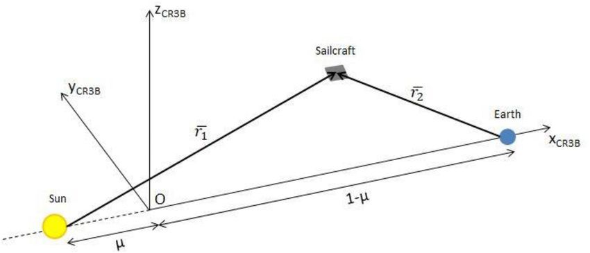
C. Fuglesang and M.G. de Herreros Miciano Acta Astronautica 186 (2021) 269–279
βμsun 2 present and, for solar sails, the force from the solar radiation pressure
as = cos α (4)
R2 (SRP) is the largest one of those. The solar wind is another, but it is
The lightness number β is a function of the sail efficiency Q and the almost four orders of magnitude smaller [22]. The SRP force acts in the
sailcraft areal density ρA (also referred to as sail load factor): direction from the Sun and to offset this with increased gravitational pull
from the sun, the equilibrium point will move further away from the
ms Earth. How much the displacement of this so called “sub-Lagrangian”
ρA = (5)
As point L1’ is depends on the external acceleration of the body, which in
The value of β serves as a figure of merit for a sailcraft and with ρA in turn depends both on the reflectivity and the mass of the body. Higher
units of g m− 2, it becomes reflectivity gives a larger SRP force and leads to a larger displacement. A
larger mass, on the other hand, “anchors” the body closer to L1 since the
1.53Q
β= (6) gravitational force becomes larger. Another way to see it is that the
ρA acceleration component from the SRP decreases with a higher mass. The
The value 1.53 represents the critical loading parameter in g m− 2. It exact new location of the point can be calculated by solving the
is the mass to area ratio that a sail, oriented perpendicular to the sun following equation (Eq. (8)), where γ = xe − (1 − μ), being xe the dis
line, should have to generate a force equal and opposite to the solar tance of the equilibrium point L1’ from the center of mass of the
gravitational force. Sun-Earth system along the Sun-Earth line and μ the mass ratio: μ =
Up to this point, the solar sail has been considered as a flat surface. In mearth
msun +mearth [16].
reality, though, the thin membrane of the sail will undulate under the
radiation pressure, modifying the total force. A force model to simulate γ 5 − (3 − μ)γ4 + (3 − 2μ)γ3 + (1 − 2μ − (β + 1)(1 − μ))γ2 + 2μγ − μ = 0
this behavior was derived by the Jet Propulsion Laboratory (Eq. (7)), (8)
where the total force is parametrized as a function of the angle α be
When considering a sunshade, there is one more aspect of interest:
tween the force of the thrust vector and the sunlight [22]. It must be
The amount of decreased light on the surface of the Earth (ΔS) from a
pointed out that, when using this expression, the force is null for angles
sunshade with a given area, decreases quadratically with the distance
larger than 61.1◦ .
from the planet (since the Sun is larger than the Earth), as given by the
F = 2PAs Q(0.349 + 0.662cos 2α − 0.011cos 4α) (7) following expression:
There is an excellent synergy between sunshades in space and solar R2Sun AShade
ΔS = (9)
sails. Both need to be large and thin, with a mass per area as small as R2Shade ASun
possible in order to reduce the launch cost from Earth, as well as to
increase maneuverability in space. However, the total area of the sun where R is the distance to Earth and A is the cross-section area as seen
shade needed to reduce the solar radiation reaching Earth by 1% is from Earth.
several orders of magnitude larger than the size of any solar sail that can As seen in (Eq. (8)), the position of L1’ depends on β and thus on the
be constructed on Earth and launched to space. area-to-mass ratio according to (Eq. (5)). Because the required shade
Approximating the Earth with a sphere of radius 6371 km, the cross area depends on the distance to the Earth as in (Eq. (9)), the position is
section area is 1.28 × 10⁸ km2. Thus, as a first approximation, the total actually uniquely defined by the mass of the system and the sail effi
sunshade area has to be at least 1.3 × 10⁶ km2. Consequently, the full ciency. As a function of the L1’ position, the mass exhibits a minimum at
sunshade system under study in this paper was defined as a constellation 2.36 × 10⁶ km from Earth (0.9842 AU from the Sun), independent on the
formed by a large number of much smaller sailcraft. This large group of sail efficiency Q and ΔS [16,24]. This can be seen in Fig. 2 for a range of
spacecraft must stay around the equilibrium point with a certain for Q-values with ΔS = 1%. At this location the total shade area required to
mation in order to form the shadow. To achieve this, a swarm control reduce the solar flux by 1% is 3.79 × 10¹² m2. The total mass at the
strategy is proposed, which would allow an autonomous group organi minimum point scales linearly with Q to compensate for the increased
zation of the sailcraft. This kind of control methods are already being solar pressure force with increased gravitational force from the Sun, as
contemplated for reduced groups of observation satellites [25] and shown in Fig. 3.
could be developed in the following years for larger groups. By using this
strategy instead of the randomly placed spacecraft cloud proposed by 4. Sailcraft conceptual design
Angel [14], it is possible to avoid the increase in the number of vehicles
needed to compensate for the fraction that could otherwise shade other It is clearly preferable to have a low Q in order to minimize the total
sailcraft. mass of the whole system. Nonetheless, a high Q is needed to fly the
A few solar sail demonstration missions have been performed, where sailcraft more efficiently from Earth to L1’. We suggest solving this by
the most successful so far have been IKAROS, in 2010 [26,27], and constructing the sails with two sides with a large difference in
LightSail-2, launched into Low Earth Orbit (LEO) in 2019 [28,29]. The
areas of these solar sails were 196 m2 and 32 m2 respectively. Several
projects studied larger sails, e.g. Sunjammer, with a sail of 1200 m2 [30],
and Heliostorm, with a 10 000 m2 sail [31], but all of them were
cancelled after the design stage.
3. Location of the sunshades
At the Lagrange point L1 in the Sun-Earth system, the gravitational
forces and the centrifugal force of a third body cancel each other. This
point is located at 1.5 × 10⁶ km from the Earth, on the line from Earth to
the Sun, 1% of the whole distance between the two bodies. A body
placed at L1 will in principle remain there if there are no other external
forces, although it is an unstable equilibrium, so in practice it will only
stay for a limited time. There are, however, always other external forces
Fig. 2. Minimum mass point location for different values of Q (from 0.2 to 0.9).
271
C. Fuglesang and M.G. de Herreros Miciano Acta Astronautica 186 (2021) 269–279
a minimum at 0.9842 AU and the total mass at this point escalates with
the sail efficiency of the sun-facing side. For the two values of Q
considered, and a solar flux reduction (ΔS) of 1%, the total mass and
corresponding areal density ρA (by dividing with the total area of 3.79 ×
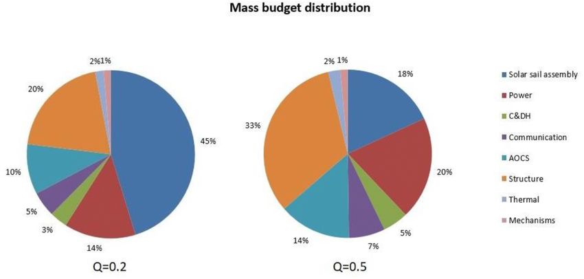
1012 m) are given in Table 1. Conceptual spacecraft designs were done
for sailcraft with areal density 9 g m− 2 for the ideal case of Q = 0.2 and
22 g m− 2 for Q = 0.5.
Based on the literature, the state of the art in solar sailing will allow
achieving an areal density of 3 g m− 2 to 4 g m− 2 for the sail assembly in
10–15 years [19,34]. We assumed that a value of 4 g m− 2 could be
achievable as explained below. The sail assembly consists of a mem
brane, four booms and a deployment mechanism. The lightest mem
brane designed so far was developed by Team Encounter, consisting of
0.9 μm Mylar coated with aluminum on one side and black chromium on
the other side, with a resulting density lower than 2 g m− 2 [35]. The
inflatable-rigidizable booms designed in this same project achieved a
linear density of 15 g/m [35], adding less than 1 g m− 2 to assemblies
with areas larger than 1600 m2. Lastly, to approximate the mass that the
deployment mechanism and the bonding of the different elements could
add, based on other solar sail designs [36], the final areal density of the
entire sail assembly was augmented with 1 g m− 2.
Fig. 3. Variation of the total mass of the system as a function of the The control system for the sail angle was not considered as part of the
sail efficiency. sail assembly, although it might be mounted on the sail. One method to
change the attitude of the sail is to adjust the position of center of
reflectivity. Although it should be possible to make a sail with an effi pressure. To achieve this adjustment, four tip vanes can be mounted in
ciency as high as 0.9, to be conservative the first assumption will be that each corner of the sail [37]. The vanes would be able to change their
one side could have Q = 0.85 [22], which will be used to get to L1’. Once orientation rotating around two axes, independent of each other,
there, the sail will be turned around and the other side with a Q as low as allowing active control in any direction. This system will be used as a
possible will face the Sun. first assumption for the attitude control, but it will add complexity to the
It would be ideal if a sail membrane could be made with a Q as low as design and deployment of the sail. Its mechanism is accounted for later
0.2. In practice, this would mean that the side facing the sun would have on in the subsystem mass budget assessment. In the end, this might not
both very low reflectively and low emissivity, while the other side would be the optimal solution and alternatives are discussed in Sec. 8.1.
have a very high emissivity. Thus, most sunlight would be absorbed, its As already noted, 4 g m− 2 of the total density corresponds to the solar
energy would penetrate through the membrane as heat, and then it sail assembly, leaving the rest for the bus configuration. The spacecraft
would be emitted in the infrared spectrum towards the Earth. Playing will need certain subsystems that are almost independent of the sail
with tools like WPTherml [32], it seems that this could be possible. For dimensions (with the exception of the structure, which must be able to
example, three thin layers (of the order of 100 nm) of TiO2, Au and Ag carry the solar sail). Once the bus design is settled, the area needed to
(from out-to inside) give a very low reflectivity in the peak of the solar achieve the selected density can be determined.
spectrum and almost no emissivity in the infrared. Adding an outer layer Considering the final location selected and the trajectory of the
with a micro-structure that would let light with optical wavelengths sailcraft, a rough first design of each one of the subsystems was carried
through, while reflecting the longer infrared heat wavelengths, would out by using as reference the mass of current off-the-shelf traditional
help to reach values of Q close to 0.2. For example, if both the reflec space elements for small satellites (some of the companies references are
tively η and emissivity on the sun facing side εF have values of 0.02 and [38,39]). However, the goal of this spacecraft definition was not to
the emissitvity on the other side εB = 0.9, Q becomes 0.2. achieve a detailed design of the subsystems, but to have an approximate
A concern could be the temperature T of the membrane. Following idea of the total mass that the bus could require.
the assumptions and method of [22], T is given by The total mass of the subsystems added up to 35 kg (which corre
[ ]14 sponds with the bus mass). To this mass, a system margin of 20% was
( )2
1 − η WE 1 added, considering this very preliminary design [40], resulting in a total
T= cos α (10)
εF + εB σ R mass of 44 kg. For a Q = 0.2 and this bus mass, the sail would need to
have an area of 8750 m2 in order to achieve an areal density of 9 g m− 2.
where WE is the solar constant with a value of 1361 W/m2, σ is the In case that the optical properties parameter had a value of Q = 0.5, the
Stefan–Boltzmann constant and R is the distance of the sailcraft from the total area would need to be 2444 m2 to achieve the density of the
sun in AU. In the worst case, with α = 0 at R = 0.98 AU, the temperature minimum mass point. The distribution of the mass among all necessary
becomes 404 K, which does not pose a problem. subsystems is depicted in Fig. 4 for both alternatives.
With common materials used currently for solar sailing, though, it is Keeping in mind that the final mass calculated for the bus did not
not easy to reach Q values in the low reflectivity side below 0.5. A account for harness or any kind of radiation protection, it was decided to
possible combination that allows reaching this value is black kapton raise it to 45 kg. Thus, the area could be defined as 9000 m2 (with a final
facing the sun and a white paint cover facing the Earth (data from an mass per sailcraft of 81 kg) or as 2500 m2 (55 kg per sailcraft) for the two
ESA presentation [33]). These properties result in a Q above 0.9 for the
“sailing side” of the membrane, but we will nevertheless stick to Q = Table 1
0.85 in our calculations. In order to explore the range from what we Total mass and areal density of the sunshade system for the two cases under
consider is state-of-the-art today (Q = 0.5), to what could ideally be study.
achieved in twenty years (Q = 0.2), we have performed calculations for
Q = 0.2 Q = 0.5
both cases and present the results in this article.
10
As mentioned previously in section 3, the mass of the system exhibits Total mass 3.34 × 10 kg 8.35 × 10¹⁰ kg
Areal density 8.8 g m− 2 21.9 g m− 2
272
C. Fuglesang and M.G. de Herreros Miciano Acta Astronautica 186 (2021) 269–279
Fig. 4. Mass budget distribution for each subsystem in percentage of the total weight of the sailcraft for both alternatives.
cases. If the final mass per spacecraft gave an areal density lower than satellites planned for the next years (e.g. Starlink [44] and OneWeb
the required (9 g m− 2 or 22 g m− 2), it should actually be increased in [45]), which are mainly in the range of 500–1500 km. The escape time
order to reach the minimum total mass for the shade system. This mass from Earth is less for higher altitudes, but, at the same time, less payload
increase could e.g. be used for redundancy of some of the most impor can be delivered there by a given launcher.
tant elements. Once in orbit, the sailcraft will deploy its sail and the solar sailing
The lifetime for CO2 in the atmosphere is several centuries, therefore starts. The trajectory was divided in two different phases: the escape
it is important to design a sailcraft with a life as long as possible. At least trajectory, where the sail leaves the gravitational field of the Earth, and
a 50 years lifetime should be aimed for to keep recurrence cost down the travel to the equilibrium point L1’. For all trajectory calculations the
(see section 7 below), and therefore each element should be designed or circular restricted three-body problem equations of motion were used. In
improved for this specific mission requirement. For this reason, even these equations, a Circular Restricted 3-Body (CR3B) reference frame is
though most of these bus components have a Technology Readiness employed, with the origin at the center of mass of the Sun-Earth-sailcraft
Level (TRL) of 9, it seemed reasonable to assume a slightly lower TRL system. The x-axis of the right-handed orthogonal system is along the
given the necessary improvements. These include for example radiation Sun-Earth line towards Earth and the z-axis is perpendicular to the
hardness, since the sailcraft will spend an extensive time in the Van ecliptic plane. The y-axis is approximately parallel to Earth’s motion
Allen radiation belts when escaping Earth, as explained in the next around the Sun (see Fig. 5). It is common to use the unit of mass as the
section. sum of the masses msun + mearth = 1, the unit of length as the distance
Still, the most important development that must be carried out from between the Sun and the Earth (1 AU) and the time unit as ω1 , where ω is
a technological point of view involves the solar sail technology [19]. the angular velocity of the Earth around the Sun. In this reference frame
Several sailing projects have reached a TRL of 7 for certain of its sub and with the units mentioned, the motion of the sailcraft can be
systems, having completed system demonstration in space environment, described as:
such as IKAROS [26,27] and LightSail 2 [28,29]. The TRL of these
¨⃗ ˙ ⃗
previous projects was classified as 7 because they aimed to prove some ⃗ ⃗
r + 2ω × r = as − ∇U (11)
technologies but not to demonstrate solar sailing as a propulsion system.
Other sailing technologies have managed to achieve a TRL between 5 where U represents the effective gravitational potential, which can be
and 6. An assessment by NASA after a 20-m ground test in 2006 written as:
concluded that TRL was between 3 and 6, depending on the subsystem ( )
x2 + y2 1− μ μ
[41]. A more recent qualification was done in 2016 within the DLR-ESA U=− − + ⃗ (12)
GOSSAMER project, reaching a TRL of 5 [42], but for a sail of 25 m2, 2 ⃗
|r1 | |r2 |
much smaller than what is considered here, although they later aim for
The position vectors r1 and r2 are defined as r1 = [ x + μ y z ] and
⃗ ⃗ ⃗
considerably larger sails. A reasonable estimate for the TRL for a sailcraft
as envisioned here, with a sail area between 2500 m2 and 9000 m2, is r2 = [ x − (1 − μ) y z ] and μ is the mass ratio as in Eg. 8. With these
⃗
between 3 and 4. dimensionless units and denoting unit vectors with “hat”( −̂ ), the SRP
acceleration becomes
5. Getting to L1′
1− μ 1− μ 2
(13)
⃗
as = β n )2 ̂
(̂r 1 ⋅̂ n=β cos α̂
n
The journey for a sunshade sailcraft to L1’ will start by launching it r21
⃗ 2
(r1 )
on a rocket from a place close to the Equator on Earth. A vehicle
launching from the Equator can take considerably more payload to a with α as defined in section 2 and shown in Fig. 1.
low-inclination orbit than one launching from a higher latitude, by For the first trajectory part, to escape from the Earth orbit, the
utilizing the rotational speed of the Earth. The sailcraft will be put in an instantaneous rate of increase of the specific orbital energy was maxi
orbit with an altitude of 2000 km, which is the very top of the so called mized, achieving a near minimum time trajectory [46]. As a conse
Low Earth Orbit (LEO) region, and well above the altitude were atmo quence, the component of the SRP acceleration along the velocity vector
spheric drag still has a small influence (up to 900 km [43]). This altitude ⃗
v must be maximized in each point by rotating the sail. The specific
was selected also because it will be above the super-constellations of orbital energy is defined as:
273C. Fuglesang and M.G. de Herreros Miciano Acta Astronautica 186 (2021) 269–279
Fig. 5. Three Body Problem reference frame.
1⃗T ⃗ μ = 0) to L1’ with the method above became 747 days, giving a total travel
Eorb = v v − Earth (14)
2 r time of 1096 days.
A disadvantage with this initial approach is that the sailcraft always
where μEarth is the Earth’s standard gravitational constant and r repre leaves the Earth’s influence with a velocity in the direction opposite to
sents the distance between the Earth’s center and the sailcraft. When the the Sun. This fact is not beneficial for the next trajectory phase, which
specific energy becomes positive, it is considered that the sailcraft has requires moving towards the Sun and not away from it, and therefore,
entered a hyperbolic trajectory and therefore can escape Earth. The adds up a considerable amount of time to the final solution. Even though
technique used here follows Coverstone and Prussing [46], but with the the travel time is not critical, since a trajectory of several years can be
additional simplification that the orbit of the Earth around the Sun was assumed when compared with the total length of the mission, a search
considered circular. for an alternative trajectory was carried out in order to reduce the final
The complete trajectory analysis presented is the one corresponding time.
to the sail membrane alternative considered most realistic (Q = 0.5), Given the complexity of unifying both phases in one and optimizing
which resulted in an optimal areal density of 22 g m− 2. Using a sail ef the trajectory as a whole, the two-phase division was maintained but a
ficiency of Q = 0.85 on the high reflectivity side, the resulting lightness modification was done in the first phase approach. The near minimum
number β = 0.0591. With this value and taking the sail force model of time strategy was applied to the escape trajectory until the energy
Eq. (7) into consideration, the resulting escape time is around 350 days. reached a certain pre-set negative value, before reaching a null orbital
The exact value depends on the time of the year when the maneuver energy. Here, the control strategy was changed to maximize the accel
starts, due to the Earth’s orbital inclination with respect to the solar eration in the direction of the velocity only when this velocity had a
ecliptic plane. component that was directed towards the Sun. A study for different
During the Earth escape it is assumed that the sail can be optimally energy values was carried out looking for the optimal exit conditions,
oriented at every instance, which poses strong requirements on the considering as such a velocity directed towards the sun combined with a
control system. Since the sail force model of Jet Propulsion Laboratory low increase in the escape time with respect the first optimization.
(Eq. (7)) is used, the sailcraft will only increase its orbital energy when With the second strategy presented and using as a pre-set energy
the sun angle is between − 61◦ and +61◦ . During the remainder of an value of − 2.94 × 10⁵ J kg− 1 (about 1% of the initial value of − 2.38 ×
orbit, the sail must rotate back by 122◦ to − 61◦ (see Ch. 4.4 in Ref. [22], 107 J kg− 1) to change the strategy, we found an escape time of 531 days
but where an ideal sail is assumed and therefore an immediate 180◦ and a total travel time of 603 days. Table 2 summarizes the values for the
rotation is made). At the starting orbit of altitude 2000 km, the time for times and positions in the critical points of this new strategy. The whole
this is around 40 min, however 32 min of that would be in the shade. It trajectory is shown in Fig. 6 and the control history for the second phase
might not be possible to design a control system based on vanes capable can be found in Fig. 7.
of achieving these changes and some alternatives are discussed in sec If the optical properties of the sailcraft would allow to reach Q = 0.2,
tion 8.1. these numbers would be reduced, since the lightness parameter would
Once Eorb has become positive, the travel to the equilibrium point L1’ have a value of β = 0.145 and therefore the efficiency of the sail would
starts. To solve the optimal control problem of how to orient the sail over
time in order to reach the goal in the minimum time possible, the so
called “direct method” was used. This method divides the whole flight in Table 2
segments with constant sail attitude in each one of them, transforming Key points in the trajectory from LEO to L1’ with Q = 0.5.
the optimal control problem into a parameter optimization. As shown by
Initial position Earth escape point L1′
Otten and McInnes [47], this nevertheless provides a near-minimum LEO
time trajectory. Twenty segments were used and the time was mini
Days to reach the 0 531 603
mized by varying the two angles that define the sail attitude per
point
segment, i.e. in total forty parameters. The SNOPT optimization soft Position ECIa (km) [8.38 0 0] × 10 3
[115 147 50] × [-1.9 − 1.2 0.6]
ware, which uses a sequential quadratic programming (SQP) algorithm, 104 × 106
was used in MATLAB [48] to find the minimum value numerically. Velocity ECIa [0 6.9 0] × 103 [− 80 472 428] [-277 -348
The final requirement set was that the velocity when arriving at L1’ (m s− 1) -155]
Position CR3B [150, − 0.0084 0] [148 0.68–0.13] × [147 0 0] × 106
must be maximum 10− 4 in dimensionless units (around 3 m s− 1) in each (km) × 106 106
coordinate direction. As previously stated, the exact numbers for the Velocity CR3B [6.32 0–2.75] × [− 423 116–204] [2.98 2.98 2.98]
final trajectory will change slightly depending on the time of the year (m s− 1) 103
when the mission starts. Considering the start of the trajectory at the a
Earth-Centered Inertial reference frame.
winter solstice, the flight time from leaving Earth’s direct influence (Eorb
274C. Fuglesang and M.G. de Herreros Miciano Acta Astronautica 186 (2021) 269–279
Fig. 6. Final trajectory of the sailcraft from LEO to L1’ and trajectory projection on the XY plane. Note difference in scale of X vs. Y and Z.
Fig. 7. Magnitude of the acceleration (left) and the angle between the sunlight and the normal to the surface (right) along the second phase of the trajectory. The
angle was limited to 61.15◦ because for angles above this value the force is null (Eq. (7)).
be higher. With the first strategy used, the escape time would result in
Table 3
190 days, with a final time to reach L1’ of 554 days. Using the second
Key points in the trajectory from LEO to L1’ with Q = 0.2.
strategy described previously, with a pre-set value for the energy of
− 3.54 × 10⁵ J kg− 1, the escape time would be 285 days, with a total Initial position Earth escape point L1′
LEO
trajectory time of 373 days. The summary of the most important points
and times in this case can be found in Table 3. Days to reach 0 285 373
the point
The final destination of the sailcraft, L1’, corresponds with the
Position ECIa [8.38 0 0] × 103 [4.82–1.52 3.17] [0.30–2.12 − 0.92]
equilibrium point for sail membrane side with the lower value for Q, but, (km) × 104 × 106
as explained previously, in order to achieve a more efficient transfer, the Velocity ECIa [0 6.9 0] × 10 3
[− 1.97 3.06 0.37] [457 56 28]
other side with a value set to Q = 0.85 was used for the trajectory phase. (m s− 1) × 103
This means that, once L1’ has been reached, the sail will need to change Position CR3B [150, − 0.0084 [150–0.010 0.035] [147 0 0] × 106
(km) 0] × 106 × 106
its orientation 180◦ in order to face the Sun with the side that was Velocity CR3B [6.32 0–2.75] × [− 1.38 3.26–0.88] [2.98 2.98 2.98]
previously in the shadow. This process could take some time and cause a (m s− 1) 103 × 103
certain drift in the position, which would have to be corrected for a
Earth-Centered Inertial reference frame.
afterwards.
As soon as the low-Q side of the sail is facing the sun, the station-
keeping strategy will start, in order to keep the sail in the desired
275C. Fuglesang and M.G. de Herreros Miciano Acta Astronautica 186 (2021) 269–279
position. The precise strategy will depend upon what will be considered such as SpaceX Starlink with around 12 000 satellites [54], this figure is
optimal at the time. It could be using a natural orbit around L1’ [49] or it around 30 000 times smaller than the number of sailcraft needed.
could be to have the sunshades follow a trajectory that would give an Consequently, the manufacturing cost approximation could not be based
optimal latitude-dependence of the shade effect, as proposed by Sanchez on previous spacecraft production experience and, in order to estimate
and McInnes [16]. this cost, a comparison with the car industry was made. The sailcraft will
be mass produced, like popular car models. The manufacturing cost of a
6. Schedule normal car is about US$10 000. However, the sailcraft will likely be less
complex than a car and only a tenth in mass. Cost can often be assumed
A single sailcraft as designed above has a sail area of 9000 m2 and a to scale with mass, and it is therefore reasonable to assume a cost of the
mass of 81 kg in the optimal case and 2500 m2 and 55 kg in the more order of US$1000 per sailcraft. Nevertheless, considering all the un
conservative case. In both options, though, the sailcraft will be posi certainties and to be conservative, this value was doubled and the final
tioned at a sub-Lagrangian point L1’ at 2.36 × 10⁶ km from the Earth estimate for the manufacturing cost was set to be between US$8 × 10¹¹
(0.9842 AU from the Sun). The total area required there to reduce the and US$2 × 10¹².
sunlight on Earth by 1% is 3.79 × 10¹² m2. Thus, 4.2 × 10⁸ sailcraft There will be additional costs, such as for development, constructing
would be needed in the first case and 1.5 × 10⁹ sailcraft for Q = 0.5. launch sites and manufacturing launch vehicles. They should all be
Assuming a launch vehicle similar to the Starship Super Heavy [50], smaller than the values given above, but rounding up to a total cost for
currently under development with a payload capacity of 100 000 kg to everything, we estimate the final values to be the ones represented in
LEO, a total of 330 000–830 000 launches would be required. (The Table 4, or to be less precise: “a few trillion” dollars.
environmental impact of these is discussed in Sect. 8.5.) Considering These costs will be spread over at least 20 years, so the deployment
that the sunshade system might need to be in place by the middle of the cost of the initial sunshade system will be in the range US$150 to US
century, and that the development required for some of the technologies $350 billion per year. It could involve many countries, which could each
will need at least 10 years, it was decided to consider a 20 years period make various contributions, from manufacturing to launch and opera
for the whole system to be put in space. These figures would mean tions, thus strengthening their industries. This will facilitate finding a
launching an average of 46 rockets a day (16 700 per year) in the political solution for financing. If such a system is needed, it will how
optimal case (Q = 0.2) and 114 a day (41 500 per year) in the case of Q ever likely be required for several centuries, since emitted CO2 stays in
= 0.5. These are numbers well above the current rate of about 100 the atmosphere for several hundred years and possibly even up to 1000
launches per year. However, space industry and space flights are slowly years [55]. Assuming an average lifetime of the sailcraft to be 50 years,
becoming more routine and compared to the 45 000 daily flights the replacement cost will be about US$100 billion per year, from the end
handled by the Federal Aviation Administration [51], something like of the current century. It can be noted that the Voyager spacecraft are
one hundred seems like a small number. It will be required to build still operating after 43 years in space [56].
several new space ports, though. Perhaps six launches per day could be
accomplished per launch site, in which case, up to twenty space ports 8. Discussion
would be needed.
8.1. Assumptions made during the study
7. Cost of the system
This paper addresses the practical feasibility of implementing a space
There are two main contributions to the total cost for such a sun sunshade system near the first Lagrangian point and estimates a cost for
shade system: manufacturing and launch from the surface of the Earth to it. During the study, several assumptions and simplifications have been
the initial orbit of 2000 km altitude. Today, in 2020, the lowest cost for done by necessity, some of the more critical ones are discussed below.
launching a mass to LEO is about US$2000/kg, compared to the old
“rule-of-thumb” which was US$10 000/kg. The price has fallen mainly (i) Solar sail membrane. Although the model selected for the solar
due to the introduction of reusable rocket stages, being the leading radiation pressure force accounts for optical and physical im
company SpaceX that currently advertises on the website a price of US perfections of the sail, the tangential force component was
$90 M for a Falcon Heavy launch, which can take up to 63 800 kg to LEO ignored, considering just a force in the direction of the normal to
[52]. The technology of reusability is continuously progressing and, in the surface. Another factor that was not considered is the
about a decade, there will likely be completely reusable launch vehicles. degradation of the membrane due to solar radiation, particle
SpaceX is well ahead in the development of their Starship and Super radiation and micrometeorites, which will also change the value
Heavy launch systems, which will be fully reusable and able to take of Q [57].
100 000 kg to LEO [50]. The CEO, Elon Musk, has claimed in an inter
view [53] that the cost for a single launch eventually could be as little as We have assumed a lifetime of 50 years, but if such a long life was not
US$2 M, slightly more than twice the cost of the propellant only possible the maintenance cost per year would increase.
(methane and liquid oxygen). That would correspond to as little as US It seems plausible that a sail membrane with a “sail efficiency” Q of
$20/kg in launch cost to LEO. On the one hand, we consider this perhaps 0.5 can be manufactured, but it should also have a low areal density,
too optimistic, but on the other hand, a launch system for millions of which has here been assumed to be 3 g m− 2. A larger areal density of the
identical sailcraft could possibly be optimized specifically for this pur membrane could be handled by increasing the area of the sail, keeping
pose, leading to a low cost. In this case, Starship with Super Heavy
would only be showing what realistically could be achieved. Never Table 4
theless, we will make a conservative estimate, assuming a launch cost of Cost calculation summary.
US$50/kg for the sunshade system. This also takes into account that
Cost (US$) Total cost Q = 0.2 Total cost Q = 0.5
prices for launching to LEO normally assume a polar orbit at 500 km per kg (US$) (US$)
altitude, while we need to go to 2000 km, albeit to an equatorial orbit.
Launch 50 1.7 × 10¹² 4.2 × 10¹²
Thus, the total launch cost for launching all sailcraft with a total mass of Spacecraft 25 8 × 10¹¹ 2.1 × 10¹²
3.4 × 10¹⁰ kg to 8.3 × 10¹⁰ kg is estimated to be around US$1.7 × 10¹² manufacturing
to US$4.2 × 10¹². Additional costs – 5 × 10¹¹ 5 × 10¹¹
The results show numbers never seen before in the space industry. Final cost of the whole 75 3 × 10¹² 7 × 10¹²
system
Although some large communication constellations are being planned,
276C. Fuglesang and M.G. de Herreros Miciano Acta Astronautica 186 (2021) 269–279
the same overall areal density of the sailcraft and total mass of the regional effects of a uniform reduction of the radiation. They found
system. Although a smaller sail would easier to design, with 6 g m− 2 and different effects depending on the latitude, achieving significant cooling
all other parameters the same, the sail area needed would be 3000 m2 on the tropics and a warming on high latitudes, even though the global
which is only 20% larger. mean temperature decreased. Nevertheless, they concluded that,
A final point is that it could be difficult to achieve a high Q on one although these regional differences would exist in the geoengineering
side and a low on the other side. It is, though, not so important to have a world, they would be small when compared with alternative scenarios
high sail efficiency. For example, with Q = 0.7, the travel time increases with high CO2 emissions and no further actions. Later on, other studies
only around 20% compared to Q = 0.85. have considered a non-uniform reduction in order to decrease these
regional effects [16,62]. As shown by Sanchez and McInnes [16], this
(ii) Attitude control and solar sail structure. Assumptions have been can be achieved by making sunshades move in certain orbits around the
made based on preliminary designs and tests of much smaller optimal L1’. To obtain an ideal differentiation of shading, it might
systems than here foreseen [35]. We estimate that today the TRL however be necessary to increase the total area, and thus the mass,
for a 9000 m2 sail is around 3. Perhaps a TRL of 9 will not be perhaps as much as 50% with respect to the values given in this paper.
feasible in even 15 years and the system will need to be more
massive, which would scale the costs proportionally. The attitude
8.4. Collision risk in orbit
control system must, for example, be sufficiently robust to turn
the sail in synchronization with the sailcraft’s orbit around Earth,
By choosing 2000 km as starting altitude, the high density of satel
which has an orbit time of just over 2 h at 2000 km (and then
lites and space debris in LEO is avoided, but the solar sail will need to
decreasing when the sailcraft’s mean altitude increases). A minor
face the GEO area. The large dimensions of the sail surface increase the
related simplification made was that the change between
possibility of it being damaged by space debris or micrometeoroids,
different angles for the second phase of the trajectory was
which would limit the performance of the vehicle. The sailcraft orbit
considered to be instantaneous. This could to some extent affect
should actually get a small inclination, which will not reflect much in
the times calculated, increasing the final results, but it would
launch cost or in time if done by SRP in the early solar sail phase, and
likely be negligible.
thereby have much lower collision risk with GEO (Geosynchronous
Equatorial Orbit) satellites. In addition, about 200 000 sailcraft will be
There are several possible ways to ease the particular challenge given
launched per day and it will probably be necessary to put them in
by an initial launch to 2000 km altitude. The simplest would of course be
slightly different orbits. Since the sailcraft are not foreseen to have any
to chose a higher altitude, but in order to keep launch costs down we
propulsion system, they will not be able to maneuver themselves quickly
decided to explore other methods. Increasing the capabilities of the sail’s
out of the way for other satellites, so careful planning will be needed. If
attitude control system by, for example, having a small electrical motor
these issues turn out to be too complex to solve, either starting in a
in addition to the control vanes could be one possibility. Another is to
higher orbit or adding a propulsion system should not be excluded,
use a small electrical propulsion system that could work in parallel with
although it would increase considerably the total cost of all launches.
the solar sail in the initial phase. There are already some on the market
having an ISP up to 6000 s [58]. The mass of the propellant needed to
raise the Orbit from 2000 km to 10 000 km using this type of propulsion 8.5. Environmental impact
would be less than 2 kg. One could also consider letting the sail continue
to rotate in one direction and on every second orbit have the An environmental impact assessment was considered necessary to
low-reflectively side face the sun. The requirement on the attitude evaluate the implementation of the system, given the final goal of the
control authority will be much less in this case, while if this is done project. If the development of the system had considerable negative
without any other measure the escape time for the sailcraft will increase effects on the climate, it would be counteracting its own objective. To
about 20%. account for these effects, the environmental impact is considered to
come from three main sources: the launches, the fuel production and the
(iii) Trajectory time. A strategy was found which showed that the manufacturing of the system.
travel time from launch to the desired L1’ point could be kept to The impact of the launches comes from emissions from the com
about 600 days. This was, though, not an absolute optimization bustion process. These emissions will depend on the fuel used. Studies
since the time is not a critical factor in the mission. It is likely that regarding rocket emissions are few and not thorough; hence the conse
the travel time can be decreased through further studies. quences of these are quite uncertain. Still, from an environmental point
of view, the use of rockets powered by liquid hydrogen (LH2) and liquid
8.2. Technology development needed oxygen (LOX), which only produces water exhaust, seems to be the best
option. Even though, it must be kept in mind that high concentrations of
The low TRL of the main technology required for the project in hand, water vapor emissions will also have an effect on the atmosphere that
a large solar sail with specific sail efficiencies (Q) for each side, means must be studied.
that a considerable amount of money will be needed for research and However, LH2 powered rockets do not seem to be present in the
development. Nonetheless, even if in the end the sunshade system is not ongoing development of heavy launchers. The vehicle considered above
implemented, the development of this kind of technology will be useful to launch the sailcraft was the Starship, which runs with methane (CH4)
for the space sector in the future. Some of the applications that solar and LOX, giving as main products of the combustion CO2 and H2O.
sailing could have include: deorbiting of satellites, acting as main pro Table 5 shows approximations of the amount of CO2 emissions
pulsion system of deep space or interplanetary missions, and enabling (considering a perfect combustion of the reactants) in the worst case
new non-Keplerian orbits [59,60].
Table 5
8.3. Climate effect latitude dependence Carbon dioxide emissions calculations for Starship launches (Q=0.5 case).
Total propellant mass per launch 4500 tonnes
This research did not carry out a climate analysis of the effects that Methane mass per launch 900 tonnes
the shade would have on Earth if implemented, but other studies Carbon dioxide emission per launch 2475 tonnes
regarding these consequences have been performed. Lunt et al. [61] Carbon dioxide emission in one year 102 million tonnes
Total carbon dioxide emissions 2054 million tonnes
were the first to use a fully coupled General Circulation Model to study
277C. Fuglesang and M.G. de Herreros Miciano Acta Astronautica 186 (2021) 269–279
scenario, which corresponds with the Q = 0.5 alternative. The total $300 billion per year, if the cost is spread over 25 years, say 2035–2060.
number of annual emissions represents only 11% of the emissions from That is a few per mille of the world GDP in that time frame. After that,
commercial aviation in 2019 [63] and 1.2% of the ones from passenger for as long as the CO2 remains in the atmosphere, the cost of maintaining
cars in 2018 [64]. Furthermore, when considering the current amount of the system is much less, while the benefits for the global economy re
CO2 in the atmosphere [65], the emissions of this project represent mains the same. If the damage to global economy and society is more
around 0.2%. These comparisons lead us to think that, even if the launch than a few times 0.1% of global GDP, it would clearly be economically
vehicle used has a certain contribution to the CO2 emissions, the advantageous to deploy a sunshade system.
magnitude of this amount could be accepted given the later benefits of
the mission. 9. Conclusion
The sustainability of the rocket fuel production shows similar out
comes for both of the fuels mentioned above. Carbon neutral fuels could The implementation of space based geoengineering techniques has
be obtained using exclusively renewable energy, which would allow the rarely been studied from a practical point of view. This paper aims to
production process to stay carbon neutral as well. Meanwhile, although shed some light to the feasibility of this practical realization in the near
methane is abundant on Earth and could be obtained as a fossil fuel, it future, offering a first approximation on how it could be achieved, the
can also be produced by an electrolysis process using CO2 and water, advancements necessary to do so and the costs.
which can be completely sustainable [66]. For these reasons, we did not It has been argued that in about 15 years, given the resources, the
consider the fuel production as a relevant factor in the environmental technology of solar sailing could be advanced to the level that a sailcraft
impact. with an area of up to 9000 m2 could be built, with the capacity to sail
Finally, the space industry manufacturing environmental impact is from a LEO of 2000 km altitude to the vicinity of the Lagrange point L1
usually not taken into account given the limited number of units that are between Earth and the Sun. These sails could be used as sunshades to
produced each year. Nonetheless, if this project was carried out, it would compensate for global temperature increase. To obtain a 1 ◦ C temper
reach numbers comparable to the car industry. Assuming that the sail ature reduction, around 1.5 billion sailcraft would be needed, with a
craft were manufactured during a 20 year time period, around 75 total system mass of 8.3 × 10¹⁰ kg. The total cost of manufacturing and
million vehicles would need to be produced per year. In 2017 the Eu launching the whole system is estimated to be in the range of US$5–10
ropean Union produced 17 million cars, with around 9.5 million tonnes trillion, based on projections on future launch vehicles. If sail membrane
of CO2 emitted in the process [67]. Given the similarity in the numbers, technology can be developed to allow coating with very low reflectivity
it was considered that these two industries could be compared, but a car and low emissivity, these numbers could be reduced considerably. The
weights around one ton, whereas the spacecraft considered has a mass of cost is in the order of 0.1% of the world GDP during the twenty years it is
55 kg. Taking this into consideration, it seemed reasonable to assume proposed to deploy the system. This is very likely much less than the cost
that the emissions of manufacturing the sailcraft would be around three of the possible damages due to an excessive temperature rise. Still, a
times smaller than the value previously mentioned, giving a total of decision to produce the whole system should not be taken before, and
around 3 million tonnes of CO2 per year, thus insignificant compared to only if, it is certain that a global temperature rise above 2 ◦ C cannot be
the launches. avoided. However, the technological development to reach at least TRL
7 within 15 years should be started immediately.
8.6. Cost of the system compared to cost of climate change to society In addition to increasing the TRL for solar sailing, the large numbers
of spacecraft and launches of the system represent the main challenge
The total cost of the proposed sunshade system to control global for the project to become a reality. Production lines of scales never seen
temperature increase is mainly driven by the launch. Elon Musk is not before in the space industry have to be set up. In any case, the next step
the only one expecting a launch cost of “tens of dollar per kilogram” by towards the development of a full system is a fairly simple and
2040, see e.g. Ref. [68] where this quote from NASA is given. The es straightforward one: make a demonstrator sailcraft of modest size (e.g.
timate we make of US$50/kg is very likely within a factor of two of what 10 m × 10 m) and show that it can solar sail from Earth orbit to L1.
it actually will be and it could well become as low as US$20-30/kg. On
the other hand, the development of the solar sail technology might not Declaration of competing interest
reach as far as we have assumed and the total mass to launch might
increase considerably. It is therefore wise to give a total cost range of The authors declare that they have no known competing financial
5–10 trillion dollar for a system that could avoid a global temperature interests or personal relationships that could have appeared to influence
increase of 1 ◦ C. If 2 ◦ C is needed, the cost will be more or less double. the work reported in this paper.
Further studies should give a better estimate of both the cost for a given
size of a sunshade system and the required size. References
In any case, the cost must be put in perspective: If not sufficient
actions are taken, what is the global damage of the corresponding [1] V. Masson-Delmotte, P. Zhai, H.-O. Pörtner, D. Roberts, J. Skea, P. Shukla, et al.,
Summary for policymakers, in: Global Warming of 1.5◦C. An IPCC Special Report
temperature increase? It is arguably very hard to predict the cost of on the Impacts of Global Warming of 1.5◦C above Pre-industrial Levels and Related
temperature increase and there is a large spread of estimates for this Global Greenhouse Gas Emission Pathways, in the Context of Strengthening the
number. In one study from 2018, Burke et al. wrote “we project 15%– Global Response to the Threat of Climate Change, Sustainable Development, and
Efforts to Eradicate Poverty, Tech. rep., IPCC, 2018.
25% reductions in per capita output by 2100 for the 2.5–3 ◦ C of global [2] J. Blunden, D. Arndt, State of the climate in 2019, Bull. Am. Meteorol. Soc. 101 (8)
warming implied by current national commitments” [69]. The world (2020), https://doi.org/10.1175/2020BAMSStateoftheClimate.1.
Global Domestic Product (GDP) today is around US$100 trillion per year [3] M.C. Hänsel, M.A. Drupp, J.A. J D, F. Nesje, C. Azar, M.C. Freeman, B. Groom,
T. Sterner, Climate economics support for the un climate, Nat. Clim. Change 10
and will continue to grow. Leimbach et al. predicted a global GDP (2020) 781–789, https://doi.org/10.1038/s41558-020-0833-x.
ranging between US$309 trillion and US$906 trillion by 2100 [70]. [4] J. Hassler, P. Krusell, C. Olovsson, The consequences of uncertainty: climate
Thus, the loss caused by a temperature increase of 3 ◦ C above pre- sensitivity and economic sensitivity to the climate, Annual Review of Economics 10
(2018) 189–205, https://doi.org/10.1146/annurev-economics-080217-053229.
industrial levels would range between US$46 and US$77 trillion for
[5] U N E Programme, Emissions Gap Report 2019, Tech. rep., UNEP, 2019.
the most pessimistic GDP forecast, and between US$136 and US$227 for [6] W. Nordhaus, Projections and uncertainties about climate change in an era of
the most optimistic one. On the other hand, other studies have suggested minimal climate policies, American Economic Journal: Economic Policy 2018 10
lower climate damage costs, e.g Nordhaus in 2018 estimated 2% of GDP, (3) (2018) 333–360, https://doi.org/10.1257/pol.20170046.
[7] P. Irvine, B. Kravitz, M. Lawrence, H. Muri, An overview of the Earth system
although stressing that there are large uncertainties [6]. To turn it science of solar geoengineering, WIREs Clim Change 7 (6) (2016) 815–833,
around, the sunshade system corresponds to an investment of about US https://doi.org/10.1002/wcc.423.
278You can also read