A New Hyperloop Transportation System: Design and Practical Integration - MDPI
←
→
Page content transcription
If your browser does not render page correctly, please read the page content below
robotics
Article
A New Hyperloop Transportation System: Design and
Practical Integration
Mohammad Bhuiya                    , Md Mohiminul Aziz, Fariha Mursheda, Ryan Lum, Navjeet Brar and Mohamed Youssef *

                                          Power Electronics and Drives Applications Lab (PEDAL), Ontario Tech University,
                                          Oshawa, ONT L1G 0C5, Canada; Mohd.bhuiya@ontariotechu.net (M.B.); md.aziz@uoit.net (M.M.A.);
                                          Fariha.mursheda@uoit.net (F.M.); ryan.lum@uoit.net (R.L.); navjeet.brar@uoit.net (N.B.)
                                          * Correspondence: Mohamed.youssef@ontariotechu.ca; Tel.: +1-905-721-8668 (ext. 5473)

                                          Abstract: This paper introduces a new Hyperloop transportation system’s design and implementation.
                                          The main contribution of this paper is the design and integration of propulsion components for a
                                          linear motion system, with battery storage. The proposed Hyperloop design provides a high-speed
                                          transportation means for passengers and freights by utilizing linear synchronous motors. In this
                                          study, a three-phase inverter was designed and simulated using PSIM. A prototype of this design
                                          was built and integrated with a linear synchronous motor. The operation of full system integration
                                          satisfies a proof-of-concept design. A study of the inverter system in conjunction with a linear
                                          synchronous motor for a ridged Hyperloop system is made. The prototype of this system achieves
                                          propulsion for the bidirectional movements. Battery state of charge simulation results are given in a
                                          typical motoring and braking scenario.

                                          Keywords: three-phase inverter; linear synchronous motor (LSM); magnetic levitation; magnetic

                                   propulsion; permanent magnet motors
Citation: Bhuiya, M.; Aziz, M.M.;
Mursheda, F.; Lum, R.; Brar, N.;
Youssef, M. A New Hyperloop
Transportation System: Design and         1. Introduction
Practical Integration. Robotics 2022,
                                                Today, transportation is a major tool for a growing economy, ranging from daily com-
11, 23. https://doi.org/10.3390/
                                          mutes to large scale freight transportation. However, with the ever-growing increase in
robotics11010023
                                          population and thus the demand for high-speed transportation raises issues regarding air
Academic Editors: António Paulo           pollution and climate change. According to data for global emissions in 2020, it was found
Moreira, Félix Vilariño and Pedro         that 24% of the global greenhouse gas emission is due to fuel dependent transportation [1].
Neto                                      Energy security and climate change are major challenges that need to be addressed for
Received: 14 December 2021
                                          the future generation. In 2016, the Paris Agreement was officially instated for the par-
Accepted: 29 January 2022
                                          ties in the agreement to address the climate change problem. This agreement is only a
Published: 8 February 2022
                                          stepping stone to combat this issue. This paper studies the design of a conceptual, novel,
                                          and electric mode of transportation known as the Hyperloop. Companies such as Virgin
Publisher’s Note: MDPI stays neutral
                                          Hyperloop One, Transpod Hyperloop, and HyperloopTT are investing in the research
with regard to jurisdictional claims in
                                          and development of the proposed Hyperloop technology. The Hyperloop system offers a
published maps and institutional affil-
                                          promising alternative to conventional train transportation, presenting a safer, faster, more
iations.
                                          reliable, and environmentally friendly method of transportation in contrast to conventional
                                          transportation. Hyperloop transport is a method of passenger and freight transport that
                                          uses vactrain design, incorporating low pressure and air resistance within a tube. Vari-
Copyright: © 2022 by the authors.
                                          ous studies such as [2,3] propose the concepts of utilizing linear motors to facilitate the
Licensee MDPI, Basel, Switzerland.        propulsion and levitation force. The study in [3] presents a Hyperloop system based on
This article is an open access article    electromagnetic propulsion of vehicles (similar technology in magnetic levitated trains)
distributed under the terms and           in vacuum tubes to reduce air pressure. Levitation is achieved by generating a repulsive
conditions of the Creative Commons        force from the tube levitation system onto the vehicle. Additionally, propulsion is achieved
Attribution (CC BY) license (https://     through a traction force generated by moving magnetic field created by linear multi-pole
creativecommons.org/licenses/by/          motors [3]. The propulsion force is generated through a spatially moving magnetic field.
4.0/).                                    This is achieved by a three-phase inverter powering and controlling the linear motor [3].

Robotics 2022, 11, 23. https://doi.org/10.3390/robotics11010023                                          https://www.mdpi.com/journal/robotics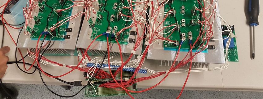
Robotics 2022, 11, 23                                                                                            2 of 15

                        The levitation of a Hyperloop can be achieved either by electromagnetic suspension (EMS)
                        or electrodynamic suspension (EDS) [4]. Due to the complexity of EMS [5], the design
                        discussed in this paper utilizes the concepts of EDS [6]. However, in practicality there
                        are many other factors, such as cost, that come into play. Thus, the use of EDS may not
                        be recommended for a full-scale system. There are two types of linear motors that are
                        commonly studied regarding magnetic levitation trains: the linear induction motor (LIM),
                        such as the one employed in [3], and the linear synchronous motor (LSM). Historically,
                        the LIM is a popular choice for magnetic levitation train. It has attractive features such
                        as cost and low complexity. However, LSM has a high-power factor and provides higher
                        efficiency [7–9]. The magnetic levitation system uses sets of superconducting magnets to
                        create repulsion and attractive forces allowing for levitation and propulsion in conjunction
                        with a linear synchronous motor [10]. The pod (vehicle) in this system travels along a
                        guideway of magnets. Stability and speed control is facilitated by sophisticated control
                        algorithms such as field-oriented control [5,10–12]. The foundation of this system is the
                        use of electromagnetism concepts as applied to thrust generation. The magnetic fields are
                        produced by permanent and superconducting magnets and electromagnets in a static or
                        dynamic mode. Superconducting electromagnets require an electric current that is signifi-
                        cantly less than conventional electromagnets [13]. The repulsive and attraction forces allow
                        for levitation and propulsion without contact. A higher lift force to magnetic ratio is ideal
                        for efficient energy consumption. Forces created depend on the placement of polarities of
                        the magnets. Lastly, the control system for the LSM drive follows the field-oriented control
                        approach. This popular control approach has been studied in various papers such as [5,14].
                        The study in [14] develops electromagnetic thrust and levitation force via field-oriented con-
                        trol. Various other papers, such as the one reported in [15], study the control of AC motors
                        using the d-q axes model. The dynamic model of a permanent magnet linear synchronous
                        motor (PMLSM) is reported in [16]. Hyperloop topics have been reported in some literature
                        works such as [17,18]. The work in [17] reports the achievability of a Hyperloop system.
                        They present the technical issues in building such an infrastructure. They estimate that a
                        Hyperloop pod traveling at 1200 km/h for an estimated weight of 26,000 kg would require
                        689 kW of power. Additionally, they calculated that the cost for building the Hyperloop
                        infrastructure in Poland of 3000–30,000 km long tracks would cost over $50 billion. In [18],
                        the authors discuss the electric power requirements for a full-scale Hyperloop. Currently,
                        there is limited research on the topic of integration of Hyperloop propulsion and levitation
                        system via linear synchronous motors. This paper is uniquely structured to give the design
                        of the inverter, linear motor, and overall integration of the system.

                        2. LSM Model and Controller Design
                        2.1. Modeling of the Linear Synchronous Motor
                             The core structure of the prototype is the linear synchronous motor (LSM) which
                        makes up the pod and the track. A diagram for an LSM is shown in Figure 1, which is
                        an unrolled form of a traditional rotary motor which consists of a stator and a rotor. The
                        symbol ‘τ’ represents the pole pitch. It is important to understand the rotary synchronous
                        machine and its properties to correctly form mathematical equations describing the motor
                        characteristics. In terms of rotary machines, characteristics such as torque, angular velocity,
                        and number of pole pairs can be defined. The linear machine can be defined with similar
                        characteristics; however, in respect to the linear machine, the terms are defined as thrust,
                        linear speed, and pole pitch. The stator is powered with three-phase AC current to produce
                        alternating magnetic fields. The rotor is a line of permanent magnets [19]. The referred
                        study uses an LSM that has an ironless core motor ideal for linear motion. The rotor is
                        the moving part (also known as the mover or the pod) lined with permanent magnets
                        and the stator is fixed on the track made up of coils (between the slots shown in Figure 1)
                        receiving the three-phase AC currents [20]. When the stator produces magnetic fields, there
                        are alternating attraction and repulsion forces created between the track and the pod. This
                        allows the pod to propel back and forth on the track without any additional assistance.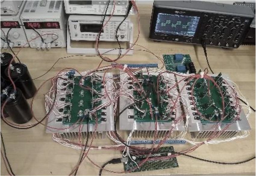
Robotics 2021, 9, x FOR PEER REVIEW 3 of 15
Robotics 2022, 11, 23 3 of 15
pod. This allows the pod to propel back and forth on the track without any additional
assistance. To model the linear synchronous motor, the mathematical model studied in
[5,10–12,21] was incorporated. For generic analysis, permanent magnet synchronous mo-
To model the linear synchronous motor, the mathematical model studied in [5,10–12,21]
tor equations were used as an equivalent to the linear synchronous motor. Additionally,
was incorporated. For generic analysis, permanent magnet synchronous motor equations
this was done because PSIM does not have a linear synchronous motor model and remod-
were used as an equivalent to the linear synchronous motor. Additionally, this was done
eling an LSM was out of scope of this research. However, it is important to note the dif-
because PSIM does not have a linear synchronous motor model and remodeling an LSM
ferences
was between
out of scope of the linear
this synchronous
research. However, motor
it is and its rotary
important counterpart.
to note The linear
the differences mo-
between
tor has different mechanical properties such as thrust force and linear
the linear synchronous motor and its rotary counterpart. The linear motor has different velocity as opposed
to torque and
mechanical angular velocity.
properties In terms
such as thrust of and
force performance, linearasmotor
linear velocity has to
opposed non idealities
torque and
such
angularas the end effect.
velocity. Thisofisperformance,
In terms caused by thelinear
unrolled,
motor opened
has non structure of such
idealities the motor.
as the The
end
end effect
effect. Thisinislinear motors
caused by theinfluences
unrolled,the propulsion
opened force
structure of and motor efficiency
the motor. [22–24].
The end effect in
However,
linear motorsthe influences
end effect the
waspropulsion
neglected in thisand
force study. Theefficiency
motor justification for this
[22–24]. is because
However, the
the
endinfluence
effect wasofneglected
end effectinisthis
notstudy.
as significant for long for
The justification primary
this islinear
becausemotors moving of
the influence at
high speedis[24].
end effect not This further simplifies
as significant the linearlinear
for long primary synchronous motor model.
motors moving at highThespeedperma-
[24].
nent magnetsimplifies
This further linear synchronous motor (PMSM)
the linear synchronous voltage
motor equation
model. in ‘abc’ form
The permanent is given
magnet in
linear
(1).
synchronous motor (PMSM) voltage equation in ‘abc’ form is given in (1).
Figure 1. Block diagram for LSM, adapted from [25].
[ d[ L ] d[i ] d[ψ Mabc ]
[ ] = [ [ u abc
][ ] =] +[ R abc ][i]abc[] + ] + [ abc ]ω[r [i abc
]
+] +[ [ L abc]] abc + ωr (1)
(1)
dθr dt dθr
where LLabc
abc is
isthe
thestator
statora,a,b,b,and
andc phase
c phase self-mutual
self-mutual inductance
inductance matrix. ThisThis
matrix. is shown in (2).
is shown in
(2).
L aa (θr ) Mab (θr ) Mac (θr )
( ) ( )
L abc = Mba (θr ) ( )Lbb (θr ) Mbc (θr ) (2)
= ( ) ( ) ( ) (2)
( ) M
( ) ca ( θ r )( )M cb ( θ r ) L cc ( θ r )
Additionally, Ψ
ΨMabc
Mabc is
is the
the stator
stator a,
a, b,
b, and
and cc phase flux linkages due to the permanent
magnets and damper windings on the rotor.rotor. This is shown in (3).
(3).
( )
Ψ Ma (θr )
( −2 )
=
Ψ Mab (θr − 2π)
Ψ Mabc =2 (3)
(3)
+
Ψ Mc θr + 3
3 2π
As seen in (1), the voltage is dependent on the phase self-inductance, which respects
As seen
the rotor in (1),ofthe
position thevoltage
PMSM.isThe dependent
solutiononof the
the phase
systemself-inductance, which
can be simplified respects
by using the
the rotor position
reference of the This
frame theory. PMSM. The solution
is achieved of the one
by taking system canvariables
set of be simplified by using the
and transforming
reference frame theory. This is achieved by taking one set of variables and transforming
it to another [11]. To transform the a, b, and c stator variables into rotor dqo axis, the
it to another [11]. To transform the a, b, and c stator variables into rotor dqo axis, the
transformation in (4) is used.
transformation in (4) is used.
2 2
( ) ( − ) ( + )
cos(θr ) cos θr −3 2π
3 2π
2⎛ 2 2 2 3⎞ cos θr + 3
= ⎜ R ( ) ( − ) )2π⎟
3⎜ Tqdo = sin(θ3r ) sin( θ+ r− 3 3⎟ sin θr + 2π3
(4)
1
3 1 1 1 1 1
2 2 2
⎝ 2 2 2 ⎠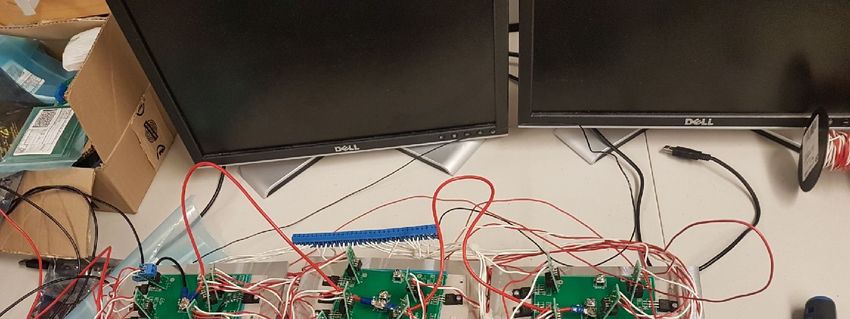
Robotics 2022, 11, 23                                                                                             4 of 15

                             The new, transformed dqo voltages are given in (5)–(7).

                                                                          dΨsq
                                                         usq = Rs isq +        + ωr Ψsd                              (5)
                                                                           dt
                                                                         dΨsq
                                                         usd = Rs isd +       − ωr Ψsd                             (6)
                                                                          dt
                                                                             dΨso
                                                              uso = Rs iso +                                       (7)
                                                                              dt
                              Using the equivalent circuits, the electromagnetic torque can be derived. However, to
                        simplify the equation, some assumptions can be made. For surface mounted rotors, the
                        reluctance torque of the motor is zero. This is because the stator q and d axis inductances
                        are equal. Assuming the PMSM does not have any damper windings and only built of
                        surface mounted magnets, then only the excitation torque will be present [11]. Thus, the
                        final derived equation for the electromagnetic torque is given in (8). As it can be seen, the
                        electromagnetic torque is dependent on the q – axis component of the stator current.

                                                                     3
                                                              Te =     p ψsd isq                                     (8)
                                                                     2

                        2.2. Permanent Magnet Configuration
                             For the pod, one important consideration is the permanent magnets’ arrangement. This
                        paper studies the use of the Halbach arrangement. The Halbach Array is an arrangement
                        of permanent magnets in such a way that the magnetic field is stronger on one side than
                        the other. This phenomenon can be realized by rotating each magnet 90 degrees from the
                        previous orientation so that the polarities of the magnets do not repeat. This causes each
                        magnet to strengthen the magnetic field on one side while a single magnet or multiple
                        magnets facing the same orientation would have uniform magnetic field strength around
                        the cluster of magnets. Employing the Halbach Array theory, the magnetic force of a linear
                        motor can be increased without increasing the size of the permanent magnets. The Halbach
                        Array is optimal for linear motors as only one side of the stator is used for levitation and
                        linear motion. The prototype was built in a way that the permanent magnets are placed
                        near the top and underside of the primary element (rotor) using a ‘C”-shaped frame. The
                        magnetic fields of the top and bottom magnet sets were aimed towards each other so that
                        the rotor could achieve higher speed, acceleration, travel accuracy, positioning accuracy,
                        and cycle times through combined attractive and repulsive forces.

                        2.3. Field Oriented Control
                             The design of FOC is based on the mathematical model of PMSM mentioned previ-
                        ously. The controller design topology is a closed loop system that includes proportional
                        integral (PI) regulators. More specifically, it includes a speed regulator and two current
                        controllers [5,11]. The block diagram for the control scheme is seen in Figure 2. The block
                        diagram also gives a general overview of the circuit design. The PMSM is controlled and
                        powered via the three-phase inverter. The inverter’s source voltage is an external dc voltage
                        source, either from a battery or from the utility rectified to a dc source. At the output of the
                        load there is a speed sensor. The remaining blocks are part of the controller. The process
                        of FOC is straightforward. As it is a closed loop design, it relies on various sensor data to
                        appropriately reach steady state. The steps are as follows. First, set a reference or desired
                        motor speed. Next, obtain three-phase current (ia , ib , and ic ) readings to convert it to qd0
                        form. Additionally, for the transformation, the rotor position of the PMSM is required. This
                        can be obtained by first reading the speed sensor value to obtain the angular velocity.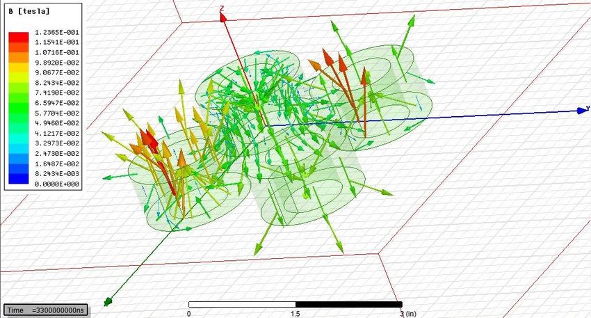
Robotics 2022, 11, 23 5 of 15
021, 9, x FOR PEER REVIEW 5 of 15
Figure 2. Block diagram
Figure for FOC control
2. Block diagramscheme.
for FOC control scheme.
Next integrate the velocity
Next integrateto get
the position
velocity to (rotor position(rotor
get position θr). These
positionfour
θrinputs
). Thesepro-four inputs provide
vide the quadrature, direct, anddirect,
the quadrature, zero currents
and zero(iqcurrents
, id, i0). These
(iq , id ,are
i0 ).the measured
These are thevalues.
measured values. The
The reference Idreference
current isIdset to zero.
current This
is set toallows the control
zero. This allows the of q-axis
control current (torque).
of q-axis current (torque). The
The reference iqreference
is obtained by first calculating the error signal of the
iq is obtained by first calculating the error signal of the speed speed (measure the (measure the
difference) then difference)
place the error
then signal
place the intoerror
a PIsignal
regulatorinto (speed regulator).
a PI regulator (speedForregulator).
the FOC For the FOC of
of the PMSM design, the output
the PMSM design,of the
theregulator
output ofisthe theregulator
iq reference.is the Theiq error signalThe
reference. of the
error signal of the
reference iq andreference
the measured
iq andiqtheis calculated.
measured iq This is then placed
is calculated. Thisinto another
is then placedregulator
into another regulator
(current regulator). A similar
(current process
regulator). A for the Id
similar loop isfor
process done.
the IdFinally,
loop is the resultant
done. signals
Finally, the resultant signals
are placed into an
areinverse
placed transformation
into an inverse block (dq0 to abc).
transformation block These
(dq0signals
to abc).are now signals
These the are now the
reference voltage for the PWM signals controlling
reference voltage for the PWM signals controlling the switching sequence of the inverter. the switching sequence of the inverter.
Additionally,
Additionally, space space width
vector pulse vector pulse width modulation
modulation (SVPWM) technique (SVPWM) technique
was imple- was implemented
mented for this for this study.
study. It works It works by obtaining
by obtaining an optimal
an optimal switching
switching sequence
sequence forforthethein-inverter switches.
verter switches. This
Thiscan
canbebeobtained
obtainedbybytakingtakingthe thesignals
signals into
intothethealpha
alphabeta frame
beta frameof reference
of [26]. The
inverter
reference [26]. The output
inverter outputvoltages
voltagesareareshown
shown in (9).
in (9).
2 −1 −1
= −1 2 −1 Va 2 −1 −1 C1 (9)
3 Vdc −1 2 −1 C2
−1 −1 2 Vb = (9)
3
Vc −1 −1 2 C3
2
= + = ( + + ) r (10)
3 2 j2π j4π
Vs = Vα + jVβ = Va + Vb e 3 + Vc e 3 (10)
3
The final signals after the PI regulator go into the SVPWM block. This facilitates an
The finalfor
optimal switching sequence signals after the
the PMSM PI regulator
control. go into the
The parameters ofSVPWM block.are
the regulator This facilitates an
optimal switching sequence for the PMSM control. The
calculated by using smart control in PSIM and analyzing the system performance.parameters of the regulator are
calculated by using smart control in PSIM and analyzing the system performance.
2.4. LSM Formulas to Generate Specifications
2.4. LSM Formulas to Generate Specifications
The power can be expressed in terms of the thrust force and the synchronous speed
The power can be expressed in terms of the thrust force and the synchronous speed
given in Equation (11).
given in The velocity
Equation (11).for
The a velocity
linear synchronous motor is given
for a linear synchronous by isthe
motor fre-by the frequency
given
quency and poleand
pitch of the motor. The thrust can be calculated by determining the mass
pole pitch of the motor. The thrust can be calculated by determining the mass and
and accelerationacceleration
of the linearofmotor.
the linear motor.
= , ∙ = ∙2 (11)
Pthrust = Fx,thrust ·vs = ma·2 f τ (11)
Additionally, the thrust density (N/m2) is described by Equation (12). Where ‘p’ is the
pole pairs, and Li is the armature stack length.
,
, =
2
= ∙2 (12)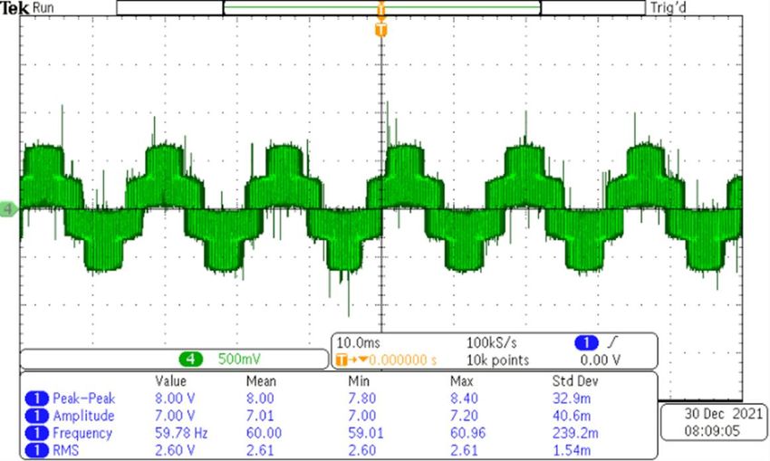
Robotics 2022, 11, 23                                                                                               6 of 15

                             Additionally, the thrust density (N/m2 ) is described by Equation (12). Where ‘p’ is the
                        pole pairs, and Li is the armature stack length.

                                                                         Fx,thrust
                                                          f x,thrust =             = ma·2 f τ                        (12)
                                                                          2pτLi

                             The efficiency and the power factor of the system are given respectively by the follow-
                        ing Equations (13) and (14).
                                                                       Fx vs
                                                            η=                                                  (13)
                                                                  Fx vs + 3I 2 R
                                                                Fx vs + 3I 2 R
                                                                PF =                                                 (14)
                                                                     3V I
                             The motor parameters used for simulation are provided in Table 1.

                        Table 1. Motor parameters.

                                    Symbol                               Quantity                 Description
                                       p                                     8                        Poles
                                       Rs                                  0.065                Stator Resistance
                                       Ld                                0.001916               d-axis inductance
                                       Lq                                  0.005                q-axis inductance
                                      Pmax                                50,000                Max motor power
                                      nmax                                 5000                  Maximum rpm

                        2.5. Modeling of Battery and Bidirectional Converter
                             The DC voltage source is provided by a lithium-ion battery. Accumulative Parameter
                        values can be calculated using (15)–(17). The parameters for a singular battery are given in
                        Table 2. The rated value can be looked up from the manufacture data sheets. Ks and Kp are
                        voltage and capacity derating factors which are set to 1.

                                                           Erated_total = NS ·KS · Erated                            (15)

                                                           Qrated_total = Np ·K p · Qrated                           (16)
                                                                                  Ns
                                                           Rbattery_total =          ·R                              (17)
                                                                                  Np battery

                        Table 2. Battery Parameters.

                                  Parameters                              Value                      Units
                            Ns No. of cells in series                       70                        cells
                           Np No. of cells in parallel                      60                        cells
                              Erated Rated voltage                          3.6                        V
                         Ecut Discharge cut-off voltage                    2.5                         V
                              Qrated Rated capacity                        3.35                        Ah

                              The parameters for the battery were calculated based on a prototype design for a
                        130-kW inverter system, with 750 VDC to power the linear motor. A typical bidirectional
                        DC/DC converter is implemented to observe the generating and motoring modes and its
                        effect on the modeled battery. The converter operates in the boost mode when the PMSM
                        is in the motoring mode of operation (i.e., battery discharging). In regenerative mode of
                        operation, the converter is the buck mode (i.e., battery charging). The block diagram for
                        the control setup is given in Figure 3. The output to this controller determines the mode of
                        operation of the buck-boost DC-DC converter.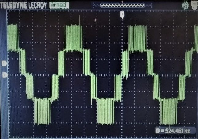
Robotics 2022, 11, 23                                                                                                     7 of 15

                                 Fig.3:

                                  Figure 3. Bidirectional DC-DC Converter Control System.

                                  3. Simulation Results
                                           The simulation setup is provided in Figure 4. The power stage includes a lithium-ion
                                     battery pack, a bidirectional dc-dc converter, a three-phase inverter, and the motor. Since
                                     the PSIM motor library was limited to only rotary motors, a permanent magnet linear
                                     synchronous motor (PMSM) was used. Thus, the angular velocity (as opposed to a linear
                                    velocity for an LSM) provided by the PMSM block was used to sense the speed for the
                                     controller. In terms of the control stage, typical FOC algorithm was used. However, to
                                     implement the regeneration system, a torque estimate was required to sense if the motor
                Fig. 4:             was in regenerative breaking or motoring mode. Thus, the additional control algorithm
                                    provided
                Please use the following figure. by PSIM was used.

                                  Figure 4. Circuit setup for FOC of PMSM.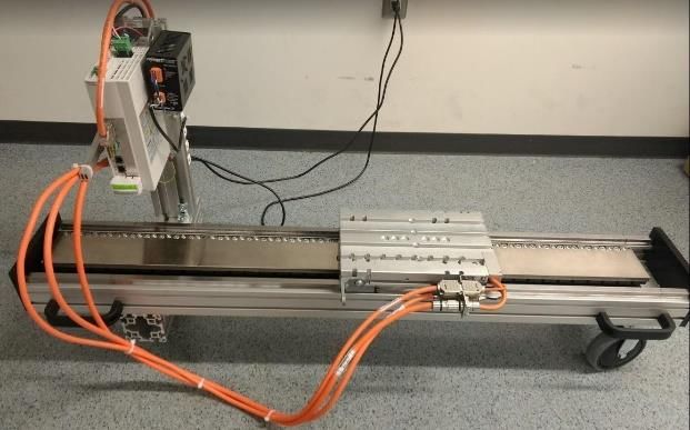
Robotics 2022, 11, 23 8 of 15
The controller will then provide the required PWM signals to produce a three-phase
2021,
21, 9, 9, x FOR
x FOR PEER
PEER REVIEW
REVIEW current waveform with minimum harmonics and to acquire a wave 8that looks
8of of1515 as sinusoidal
as possible. The following figures are simulation results of the power inverter. Figure 5
5 5shows
showsthethesimulation
simulation
shows theresults
ofofthe
simulation
results theAC
ACcurrents
currents
results inin
of the ACmotoring
currents
motoring mode. Thespeed
in motoring
mode. The speed response
mode. The speed response is
response
isisgiven
giveninin Figure
Figure 6.6. in Figure 6.
given
Figure
Figure 5. 5. Three-phase
Three-phase AC
FigureAC line
5.line currents
currents
Three-phase (amperage
(amperage
AC vs.vs. time).
time).
line currents (amperage vs. time).
Figure
Figure 6. 6. Speed
Speed response
response (rads/s vs. time).
Figure (rads/s
6. Speedvs.response
time). (rads/s vs. time).
Figure7 7highlights
Figure highlights the
Figure the7directionality
directionality
highlights the ofof thecurrent
the currentinin
directionality relation
ofrelation totothe
the current the battery.This
inbattery.
relation This
to the battery. This
direction is dependent
direction is dependent on
on if
direction if
is the the pod is in
pod is inon
dependent fact
fact driving,
driving,
if the regenerative
pod isregenerative braking,
braking,
in fact driving, or idling.
or idling.
regenerative ForFor or idling. For
braking,
example,beginning
example, beginning atat0.5
example, 0.5sbeginning
s whenthe
when the vehicle
vehicle
at enters
enters
0.5 s when regenerative
regenerative
the braking,
braking,
vehicle enters wewecan
regenerative cansee
seethe
the we can see the
braking,
currentflowing
current flowinginto
intothe
currentthebattery
batteryand
flowing andtherefore
into therefore
the battery returning
returning energy
energy
and therefore totothe
thesystem.
returning system.
energy to the system.
In Figure 8 the waveform represents the SOC during the various drive states of the
simulation. The figure first shows a decreasing SOC which indicates that the vehicle is
drawing current from the battery to drive. An increase in SOC then occurs as regenerative
braking is employed returning potential energy to the battery module. Lastly, we see that
a period of minimal drain upon the SOC in this time frame is representative of the LSM
idling until driving is resumed.
Figure
Figure 7. 7. Battery
Battery current
current forfor regenerative
regenerative breaking
breaking (amperage
(amperage vs.vs. time).
time).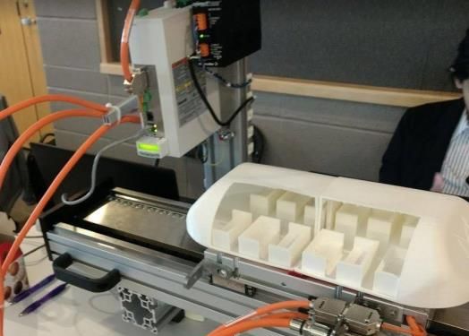
Robotics 2022, 11, 23                                                                                                     9 of 15

            Fig. 7

                        Fig. 8:

                        Please use Figure  7. Battery
                                   this figure        current for regenerative breaking (amperage vs. time).
                                                instead.

                                   Figure 8. SOC of the battery.

                                        Finite element analysis of the pod is given in Figure 9 and shows magnetic field safe
                                   values for humans as per IEEE C95.1.
                        Fig: 9          Next, the simulation is run so that the ideal distance can be determined. Once the
                                   single coil is set up, the simulation is expanded to four coils as shown in Figure 10. The
                                   effect of the adjacent coils can be observed and recorded accordingly. Figure 11 illustrates
                                   the magnetic field strength of the active coils. These levels adhere to the IEC-60118 used in
                                   North America and Europe.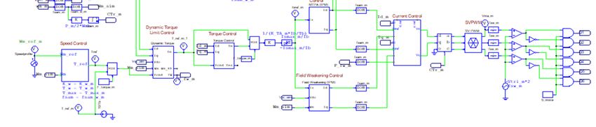
Robotics 2022, 11, 23                                                                                            10 of 15

              Fig: 9

                         Fig: 10
 Robotics 2021, 9, x FOR PEER
                                  Figure 9. Single Coil Setup in ANSYS Maxwell.
                               REVIEW                                                                            11 of 17

                                   Figure 10. Four coil simulations.
                                  Figure 10. Four coil simulations.
                        Fig: 11

                                  Figure  11.Magnetic
                                   Figure11. Magneticfield
                                                       fieldstrength
                                                             strengthacross
                                                                      acrossZZdistance.
                                                                               distance.

                                   4. Experimental Analysis
                                       Autodesk Eagle was used to design the printed circuit board (PCB). The hardware
                                   prototype of the inverter is circuit driven by the MIC4609 driver. A Texas Instrument
                                   microcontroller (TMS320F2808) was used to generate the PWM signals based on the
                                   proposed FOC. This prototype design was done to provide a proof of concept. The
Robotics 2022, 11, 23 11 of 15
4. Experimental Analysis
Autodesk Eagle was used to design the printed circuit board (PCB). The hardware
prototype of the inverter is circuit driven by the MIC4609 driver. A Texas Instrument
microcontroller (TMS320F2808) was used to generate the PWM signals based on the pro-
posed FOC. This prototype design was done to provide a proof of concept. The controller
and the PCB circuit have similar components to the original proposed design. The proto-
type for the power inverter is shown in Figure 12. It consists of 6 surface mount IGBTs
(RGT50NS65DGT) connected in a typical inverter circuit orientation. Using the data sheet
bootstrap capacitors and diodes were chosen as recommended.
Fig. 12
Figure 12. Three-phase inverter prototype.
The waveforms generated by the output of the inverter are given in Figures 13 and 14.
Figure 13 shows the preliminary inverter output voltage. In Figure 14 the purple waveform
is the voltage line feeding the load (linear motor). The green sinusoidal waveform below
it is the AC current waveform of a single phase. The results are what is expected for the
circuit output. The interface for controlling the linear motor was created using C++. It
allows the control of position, velocity, and acceleration. It also provides real-time feedback
of the motor’s status.
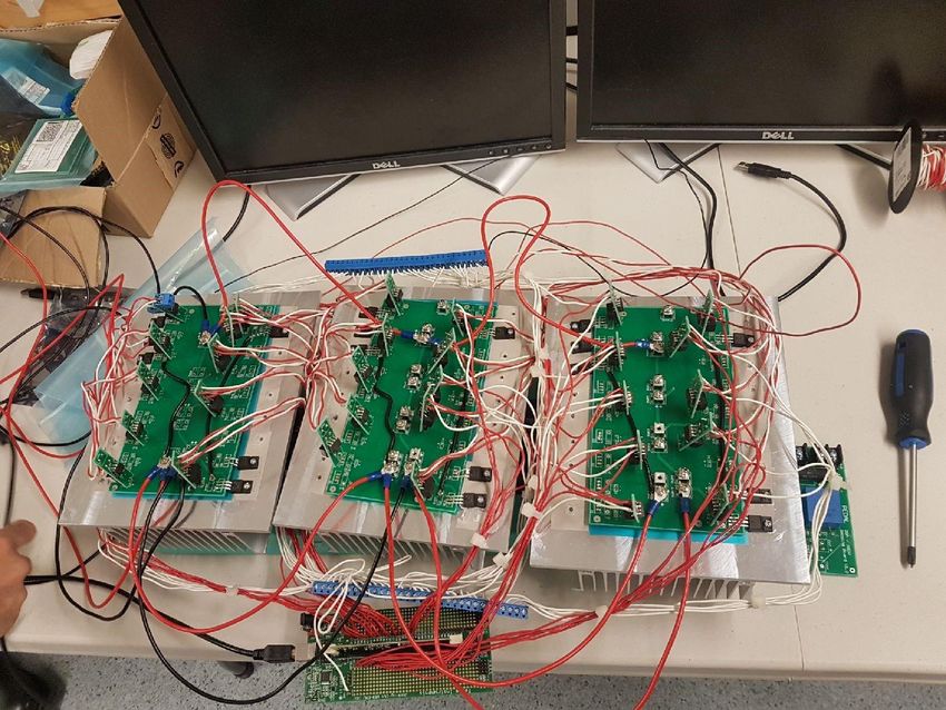
The developed inverter circuit was used to power and control the linear motor (pro-
vided by Bosch Rexroth). The prototype of the integration is shown in Figures 15 and 16.
Communication with the synchronous linear motor was achieved through Ethernet Proto-
cols. The MCP015A-L040 drive was used to facilitate prototype integration.The waveforms generated by the output of the inverter are given in Figure 13 and
Figure 14. Figure 13 shows the preliminary inverter output voltage. In Figure 14 the purple
waveform is the voltage line feeding the load (linear motor). The green sinusoidal
waveform below it is the AC current waveform of a single phase. The results are what is
Robotics 2022, 11, 23 expected for the circuit output. The interface for controlling the linear motor was 12 created
of 15
Figure 12. Three-phase inverter prototype.
using C++. It allows the control of position, velocity, and acceleration. It also provides real-
time feedback of the motor’s status.
The waveforms generated by the output of the inverter are given in Figures 13 and
14. Figure 13 shows the preliminary inverter output voltage. In Figure 14 the purple wave-
form is the voltage line feeding the load (linear motor). The green sinusoidal waveform
below it is the AC current waveform of a single phase. The results are what is expected
for the circuit output. The interface for controlling the linear motor was created using C++.
It allows the control of position, velocity, and acceleration. It also provides real-time feed-
back of the motor’s status.
Figure 13.Line
Line to line voltage waveform (Vab); before the dv/dt filterofofthe
the motor.
Figure 13.13.
Figure Linetotoline
linevoltage
voltagewaveform
waveform(Vab); before
(Vab); thethe
before dv/dt
dv/dtfilter
filter of themotor.
motor.
Robotics 2021, 9, x FOR PEER REVIEW 12 of 15
Communication with the synchronous linear motor was achieved through Ethernet Pro-
Figure
tocols. Prototype
14.14.
Figure The inverter
Prototype circuit
inverter
MCP015A-L040 waveforms.
circuit
drive waveforms.
was used to facilitate prototype integration.
The developed inverter circuit was used to power and control the linear motor (pro-
vided by Bosch Rexroth). The prototype of the integration is shown in Figures 15 and 16.
Figure15.
Figure 15.Prototype
Prototypelinear
linearmotor.
motor.Robotics 2022, 11, 23 13 of 15
Figure 15. Prototype linear motor.
Figure 16. Prototype linear motor with test pod.
Figure 16. Prototype linear motor with test pod.
5.5.Conclusions
Conclusions
AAsuccessful
successfulcomponent
componentdesign designand
andsystem
systemintegration
integrationofofthe theHyperloop
Hyperlooppod’s
pod’sfunc-
func-
tionalityisispresented
tionality presentedusingusingPSIM
PSIMsimulation,
simulation,C++ C++software
softwareinterface,
interface,and
andaaprototype
prototype
hardware
hardwarefrom from“off-the-shelf”
“off-the-shelf”components.
components.Simulations
Simulationsofoffield-oriented
field-orientedcontrol
controlfor
foranan
equivalent
equivalentrated
ratedrotary
rotarysynchronous
synchronousmotor motorwas wasbuilt
builtininPSIM.
PSIM.WithWithintensive
intensivehardware
hardware
and
andsoftware
softwareintegration
integrationmethods,
methods,the thegoal
goaltotoprovide
providelinear
linearbidirectional
bidirectionalmovement
movementfor for
the
theprototype
prototypewas wasachieved.
achieved. The
Theintegrated
integrated system
system includes
includes thethe
linear synchronous
linear synchronous motor,
mo-
three-phase power
tor, three-phase inverter,
power and aand
inverter, battery pack. pack.
a battery This wasThisimplemented
was implemented on a small-scale
on a small-
prototype model. The three-phase inverter was designed using PSIM’s
scale prototype model. The three-phase inverter was designed using PSIM’s platform platform and tested
and
by generating
tested case study
by generating case simulations that validated
study simulations its functionality
that validated before
its functionality integration.
before integra-
Additionally, the battery
tion. Additionally, modelmodel
the battery was alsowasimplemented
also implemented in PSIM and sized
in PSIM accordingly.
and sized accord-
Measured results from
ingly. Measured resultsthefrom
inverter prototype
the inverter are in good
prototype are in agreement with thewith
good agreement simulation
the sim-
results.
ulationThe operation
results. of the fullofsystem
The operation the fullintegration proves that
system integration the design
proves of design
that the the inverter
of the
and linear synchronous motor achieve a linear motion, with bidirectional
inverter and linear synchronous motor achieve a linear motion, with bidirectional move- movement for
the pod prototype, in motoring and braking modes. The presented
ment for the pod prototype, in motoring and braking modes. The presented design pro-design provides a good
starting
vides a point
good for a linear
starting pointsynchronous
for a linear motor-based
synchronous Hyperloop.
motor-basedHowever,Hyperloop. theHowever,
scale it
was designed for is currently not capable of a full-sized passenger transportation. The
nature of the system comes with high infrastructure build time and costs. Thus, various
design trade-offs were needed to be made in terms of cost, size, power capabilities, etc.
Nonetheless, future work for this study includes improving the design in various aspects
such as fine-tuning and verifying the system in a hardware in the loop environment, de-
signing it for a larger test track, and improving the prototype design capabilities to include
additional data such as speed and acceleration. Hardware in the loop technology will be
used in the hopes to reduce cost and prototyping time. A longer test track would provide a
better understanding of the performance and efficiency. Additionally, this test track would
provide a better study for the dynamic characteristics. This would require an improved
prototype design with additional sensors to provide speed and acceleration values. Lastly,
as this is the first iteration of the prototype, the design choices and trade-offs were very
minimal. The prototype was designed for a proof of concept. The next iteration will be
designed and better engineered to achieve an optimal design. Future work will also detail
mechanical modeling and passenger ride comfort calculations. To summarize, the scope of
this study is to provide some insight on the propulsion system design methodology and
initial prototype results for the novel Hyperloop transportation system.Robotics 2022, 11, 23 14 of 15
Author Contributions: Conceptualization, M.M.A. and M.Y.; methodology, M.B.; software, M.M.A.
and F.M.; validation, N.B.; formal analysis, F.M.; investigation, M.B.; resources, M.Y.; data curation,
R.L.; writing—original draft preparation, R.L.; writing—review and editing, M.B.; visualization, F.M.;
supervision, M.Y.; project administration, M.Y.; funding acquisition, M.Y. All authors have read and
agreed to the published version of the manuscript.
Funding: This work was supported by the Natural Science and Engineering Research Council of
Canada in conjunction with Transport Canada (Fund number 210850). This was an invited paper and
the APC discount was provided by MDPI. We thank MDPI for this opportunity.
Institutional Review Board Statement: This study did not require ethical approval. Not applicable.
Conflicts of Interest: The authors declare no conflict of interest.
Nomenclature
LIM Linear Induction Motor
LSM Linear Synchronous Motor
PMSM Permanent Magnet Synchronous Motor
EMS Electromagnetic Suspension
EDS Electrodynamic Suspension
POD Referring to Hyperloop Capsule/Vehicle
FOC Field Oriented Control
SVPWM Space Vector Pulse Width Modulation
uabc Stator a, b, c phase to neutral voltages
Rabc Stator a, b, c phase resistances
iabc Stator a, b, c phase currents
Labc Matrix of stator phase self and mutual inductances
Laa , Lbb , Lcc Stator a, b, c phase self-inductances
Mab , Mac , Mba , Mbc , Mca , Mcb Mutual inductances of stator a, b, c phases
ΨMabc Stator a, b, c phase flux linkages from PMSM
Te Electromagnetic Torque
SOC State of Charge
Erated Rated voltage of battery cell
Qrated Rated capacity of battery cell
Rbattery Internal resistance of the battery cell
Np Number of cells in parallel of battery pack
Np Number of cells in parallel of battery pack
References
1. IEA. Transport: Improving the sustainability of passenger and freight transport, International Energy Agency. Available online:
https://www.iea.org/topics/transport (accessed on 22 September 2019).
2. Ji, W.Y.; Jeong, G.; Park, C.B.; Jo, I.H.; Lee, H.W. A Study of Non-Symmetric Double-Sided Linear Induction Motor for Hyperloop
All-In-One System (Propulsion, Levitation, and Guidance). IEEE Trans. Magn. 2018, 11. [CrossRef]
3. Janzen, R. TransPod Ultra-High-Speed Tube Transportation: Dynamics of Vehicles and Infrastructure. Procedia. Eng. 2017, 199,
8–17. [CrossRef]
4. Hasirci, U.; Balikci, A.; Zabar, Z.; Birenbaum, L. Experimental performance investigation of a novel magnetic levitation system.
IEEE Trans. Plasma. Sci. 2013, 5, 1174–1181. [CrossRef]
5. Sayeed, J.M.; Abdelrahman, A.; Youssef, M.Z. Hyperloop Transportation System: Control, and Drive System Design. In
Proceedings of the IEEE Energy Convers. Congr. Expo. (ECCE 2018), Portland, OR, USA, 23–27 September 2018; pp. 2767–2773.
[CrossRef]
6. Zhang, Z.; She, L.; Zhang, L.; Shang, C.; Chang, W. Structural optimal design of a permanent-electro magnetic suspension magnet
for middle-low-speed maglev trains. IET Electr. Syst. Transp. 2011, 2, 61–68. [CrossRef]
7. Lim, J.; Jeong, J.H.; Kim, C.H.; Ha, C.W.; Park, D.Y. Analysis and Experimental Evaluation of Normal Force of Linear Induction
Motor for Maglev Vehicle. IEEE Trans. Magn. 2017, 11. [CrossRef]
8. Jeong, J.H.; Lim, J.; Ha, C.W.; Kim, C.H.; Choi, J.Y. Thrust and efficiency analysis of linear induction motors for semi-high-speed
Maglev trains using 2D finite element models. In Proceedings of the 2016 IEEE Conference on Electromagnetic Field Computation
(CEFC), Miami, FL, USA, 13–16 November 2016. [CrossRef]
9. Wang, H.; Li, J.; Qu, R.; Lai, J.; Huang, H.; Liu, H. Study on High Efficiency Permanent Magnet Linear Synchronous Motor for
Maglev. IEEE Trans. Appl. Supercond. 2018, 3. [CrossRef]Robotics 2022, 11, 23 15 of 15
10. Boldea, I. Linear Electric Machines, Drives, and Maglevs Handbook, 1st ed.; CRC Press: Boca Raton, FL, USA, 2017.
11. Yesilbag, E.; Ergene, L.T. Field oriented control of permanent magnet synchronous motors used in washers. In Proceedings of the
2014 16th International Power Electronics and Motion Control Conference and Exposition, Antalya, Turkey, 21–24 September 2014;
pp. 1259–1264. [CrossRef]
12. U.S.E.P. Agency. Global Greenhouse Gas Emissions Data. Available online: https://www.epa.gov/ghgemissions/global-
greenhouse-gas-emissions-data (accessed on 21 March 2020).
13. Voltes-Dorta, A.; Becker, E. The potential short-term impact of a Hyperloop service between San Francisco and Los Angeles on
airport competition in California. Transp. Policy 2018, 71, 45–56. [CrossRef]
14. You, C.; Zhang, R.; Wang, X.; Du, Y.; Ge, Q. Vector control of maglev PMLSM based on minimum loss SVPWM method.
In Proceedings of the 2016 19th International Conference on Electrical Machines and Systems (ICEMS), Chiba, Japan, 13–16
November 2016.
15. Sadat, A.R.; Shadabi, H.; Sabahi, M.; Sharifian, M.B.B. Tracking of X-Y direction positions with using permanent magnet linear
synchronous motors. In Proceedings of the 2014 22nd Iranian Conference on Electrical Engineering (ICEE), Tehran, Iran, 20–22
May 2014; pp. 527–532. [CrossRef]
16. Wang, K.; Ge, Q.; Shi, L.; Li, Y.; Zhang, Z. Development of ironless Halbach permanent magnet linear synchronous motor for
traction of a novel maglev vehicle. In Proceedings of the 2017 11th International Symposium on Linear Drives for Industry
Applications (LDIA), Osaka, Japan, 6–8 September 2017. [CrossRef]
17. Kowal, B.; Ranosz, R.; Klodawski, M.; Jachimowski, R.; Piechna, J. Demand for passenger capsules for Hyperloop High-Speed
Transportation System -case study from Poland. IEEE Trans. Transp. Electrif. 2021. [CrossRef]
18. Tbaileh, A.; Elizondo, M.; Kintner-Meyer, M.; Vyakaranam, B.; Agrawal, U.; Dwyer, M.; Samaan, N. Modeling and Impact of
Hyperloop Technology on the Electricity Grid. IEEE Trans. Power Syst. 2021, 5, 3938–3947. [CrossRef]
19. Pan, S. Development of Permanent Magnet Tubular Linearmotor and Position Feedback Device Based on Hallsensor. Univ
Wollongong Thesis Collect. 1954–2016. Available online: https://ro.uow.edu.au/theses/4852 (accessed on 14 December 2021).
20. MATLAB, “PMLSM”. Available online: https://www.mathworks.com/help/physmod/sps/ref/pmlsm.html (accessed on 14
December 2021).
21. Ong, C.-M. Dynamic Simulations of Electric Machines; Prentice Hall: Hoboken, NJ, USA, 1998.
22. Giangrande, P.; Cupertino, F.; Pellegrino, G. Modelling of linear motor end-effects for saliency based sensorless control. In
Proceedings of the 2010 IEEE Energy Conversion Congress and Exposition, Atlanta, GA, USA, 12 September 2010; pp. 3261–3268.
[CrossRef]
23. Platen, M.; Henneberger, G. Examination of leakage and end effects in a linear synchronous motor for vertical transportation by
means of finite element computation. IEEE Trans. Magn. 2001, 37, 3640–3643. [CrossRef]
24. Lu, J.; Ma, W. Research on end effect of linear induction machine for high-speed industrial transportation. IEEE Trans. Plasma Sci.
2011, 39, 116–120. [CrossRef]
25. Gieras, J.F.; Piech, Z.J.B.; Tomczuk, B. Linear Synchronous Motors: Transportation and Automation Systems; CRC Press: Boca Raton,
FL, USA, 2011.
26. Abassi, M.; Khlaief, A.; Saadaoui, O.; Chaari, A.; Boussak, M. Performance analysis of FOC and DTC for PMSM drives using
SVPWM technique. In Proceedings of the 16th Int. Conf. Sci. Tech. Autom. Control Comput. Eng. STA 2015, Monastir, Tunisia,
21–23 December 2015.You can also read