2021 MODIFIERS GUIDE F-150 Hybrid - Ford Fleet
←
→
Page content transcription
If your browser does not render page correctly, please read the page content below

2021

F-150 Hybrid
MODIFIERS GUIDE
         2021 F-150 Hybrid Modifiers Guide, 1/2021   © Copyright Ford 2020 FoMoCo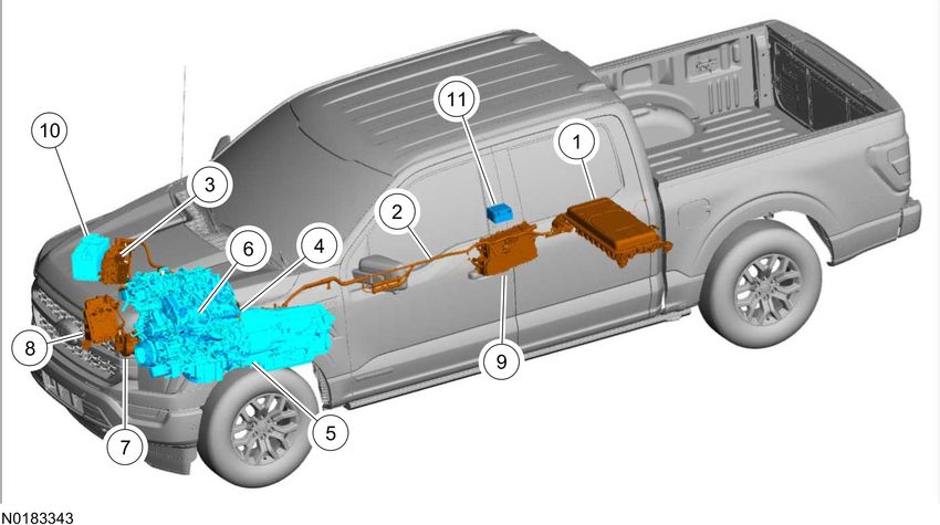
SECTION 0: Introduction

                                                                               Table of Contents
Contents                                                                                                                                                                                              PAGE

   Introduction ...................................................................................................................................................................................    0-2
        Genuine Ford Accessories For Your Vehicle ..........................................................................................................................                           0-2
        Considerations When Using or Installing Accessories ...........................................................................................................                                0-2

                                                                   2021 F-150 Hybrid Modifiers Guide, 1/2021                                               © Copyright Ford 2020 FoMoCo
0-2                                                                                                                                  Introduction

                                                  Introduction

Introduction

NOTE:
Please note this manual does not apply to hybrid responder vehicles for upfitting. For hybrid responder vehicles please refer to the
Responder Modifiers Guide.

Ford Motor Company has assembled this guide to assist vehicle modifiers in producing a safe and quality vehicle. Ford believes safety and
quality come first. To achieve customer satisfaction, we want to assist modifiers in achieving the highest standards of safety and quality in their
vehicles.
This book is divided into topics pertinent to vehicle modifiers. References are made to the current Workshop Manual for appropriate service
procedures, torque specifications, component separation clearances and other standard information which is common with an unmodified
vehicle. Specifications unique to this guide are designated.
This modifier guide is not a "how-to" book; it should be used as a checklist to help make sure that certain important steps in the modification
process are considered. While Ford is providing this information to assist modifiers, it does not warrant the vehicles, methods, materials or the
workmanship of the modifier. Ford also does not warrant against failures that result from the modification of a vehicle.
Following the guidelines contained in this guide does not assure individual modifiers that the products they modify comply with US Federal or
Canadian Motor Vehicle Safety Standards in effect at the time of the modification. The guidelines set forth are based on engineering analysis
of typical vehicles. If the guidelines are followed, the modifier's efforts in certifying vehicles to applicable standards should be aided.
Compliance testing that may be required for certification of specific vehicle configurations or construction is the sole responsibility of the
individual modifier.

Genuine Ford Accessories For Your Vehicle
A wide selection of genuine Ford accessories are available for your vehicle through your local authorized Ford or Ford of Canada dealer.
These quality accessories have been specifically engineered to fulfill your automotive needs; they are custom designed to complement the
style and aerodynamic appearance of your vehicle. In addition, each accessory is made from high-quality materials that meet or exceed Ford's
rigorous engineering and safety specifications. Ford Motor Company will repair or replace any properly installed genuine Ford accessory found
to be defective in factory-supplied materials or workmanship during the warranty period, as well as any component damaged by the defective
accessory. The accessory will be warranted for whichever provides you the greatest benefit:

•     12 months or 20,000 km (12,000 mi), whichever occurs first; or
•     the remainder of your new vehicle limited warranty.

This means that genuine Ford accessories purchased along with your new vehicle and installed by the dealer are covered for the full length of
your new vehicle's limited warranty — 3 years or 60,000 km (36,000 mi), whichever occurs first. Contact your dealer for details and a copy of
the warranty.

Considerations When Using or Installing Accessories
For maximum vehicle performance, keep the following information in mind when adding accessories or equipment to your vehicle:

•     When adding accessories, equipment, passengers and/or luggage to your vehicle, do not exceed the gross vehicle weight rating (GVWR)
      or gross axle weight rating (GAWR) as indicated on the Safety Compliance Certification Label. Consult your dealer for specific weight
      information.
•     The Federal Communications Commission (FCC) and Canadian Radio Telecommunications Commission (CRTC) regulates the use of
      mobile communication systems, such as 2-way radios, telephones and theft alarms that are equipped with radio transmitters. Any such
      equipment installed in your vehicle should comply with FCC or CRTC regulations and should only be installed by a qualified service
      technician.
•     Mobile communication systems may harm the operation of your vehicle, particularly if they are not properly designed for automotive use.
•     To avoid interference with other vehicle functions, such as the anti-lock brake system (ABS), amateur radio users who install radios and
      antennas onto their vehicle should not locate the antenna in the area of the driver's side hood.
•     Electrical or electronic accessories or components that are added to the vehicle by the dealer or the owner may adversely affect battery
      performance and durability.

                                                    2021 F-150 Hybrid Modifiers Guide, 1/2021                    © Copyright Ford 2020 FoMoCo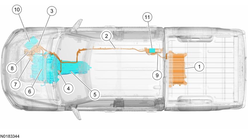
SECTION 1: General Information

                                                                            Table of Contents
Contents                                                                                                                                                                                       PAGE

   Section 1: General Information .....................................................................................................................................................         1-2
      Important Safety Notice ..........................................................................................................................................................        1-2
      Good Practices .......................................................................................................................................................................    1-3
      New Vehicle Storage ..............................................................................................................................................................        1-3
      Tires and Loading ...................................................................................................................................................................     1-4
      Ambient Temperature Change and Tire Pressure ..................................................................................................................                           1-6
      Ride Height Measurement — Front ........................................................................................................................................                  1-7
      Ride Height Measurement — Rear .........................................................................................................................................                  1-9
      Ride Height Specifications ......................................................................................................................................................         1-9

                                                                 2021 F-150 Hybrid Modifiers Guide, 1/2021                                            © Copyright Ford 2020 FoMoCo
1-2                                                                                                                         General Information

                                Section 1: General Information

Section 1: General Information
Important Safety Notice

NOTE:
The descriptions and specifications contained in this guide were in effect at the time this guide was approved for printing. Ford Motor
Company reserves the right to discontinue models at any time, or change specifications or design without notice and without incurring
obligation.

Appropriate repair methods and procedures are essential for the safe, reliable operation of all motor vehicles as well as the personal safety of
the individual doing the work. This guide provides general direction and guidelines for performing modifications to the vehicle, which will help
assure reliability.
There are numerous variations in procedures, techniques, tools and parts for modifying vehicles, as well as in the skill level of the individual
doing the work. This guide cannot possibly anticipate all such variations and provide advice or cautions as to each. Accordingly, anyone who
departs from the instructions provided in this guide must first establish that they compromise neither their personal safety nor the vehicle
integrity by the choice of methods, tools or parts.

Warnings, Notices and Notes
As you read through this guide, you will come across WARNINGS, NOTICES and NOTES. Each one is there for a specific purpose.
WARNINGS remind you to be especially careful in those areas where carelessness can cause you personal injury. NOTICES are given to
prevent you from making an error that could damage the vehicle or the vehicle's components. NOTES give you added information that will
help you to complete a particular procedure. The following list contains some generalized warnings that you should follow when working on a
vehicle.

      WARNING:

•     The nominal High Voltage Traction Battery (HVTB) voltage is approximately up to 450 Volts DC. The HVTB and charging system
      contain high voltage components and wiring. High voltage cables and wiring are orange in color. Before carrying out any
      vehicle modifications, the HVTB must be depowered. Any modification, service, or repairs to the high voltage system or its
      components, must be done by a trained service technician. Failure to follow these instructions may result in severe personal
      injury or death.
•     If applicable, make sure vehicle is not on plug in charging.
•     For eye protection, always wear safety glasses.
•     Use safety stands whenever a procedure requires you to be under the vehicle.
•     Make sure the ignition switch is always in the OFF position, unless otherwise required by the procedure.
•     Make sure the key fob is removed from the vehicle and is kept at least 3 meters (9.8 feet) away from the vehicle.
•     Set the parking brake when working on the vehicle. The gear selector should be set in PARK unless instructed otherwise for a
      specific operation. Place wheel chocks against the front and rear surfaces of the tires to help prevent the vehicle from moving.
•     Do not smoke while working on a vehicle.
•     To reduce the risk of injury, always remove rings, watches, loose hanging jewelry and loose clothing before working on a
      vehicle.
•     When it is necessary to work under the hood, keep hands and other objects clear of the cooling fan blades.
•     Failure to follow these instructions may result in personal injury or death.

NOTICE:

•     Do not modify the cooling system. High voltage vehicle components may be damaged if any cooling system modifications are
      attempted.
•     Before placing the vehicle in a paint booth, make sure that the HVTB is not installed in the vehicle. In addition, the Charge
      Status Indicator (CSI) must be covered / protected from heat. High paint booth temperatures may damage the HVTB and the
      CSI.
•     Depower the High Voltage system before carrying out any vehicle modifications.
•     Make sure the 12 volt battery negative cable is disconnected.

Making Safety Devices and Elements Inoperative
The vehicle contains many safety features required by US Federal or Canadian Motor Vehicle Safety Standards. These features, which
include the key-on-ignition chime and brake lights, should never be disabled or modified.

•     Make sure the pedestrian alert sound system is not disabled.

                                                    2021 F-150 Hybrid Modifiers Guide, 1/2021                   © Copyright Ford 2020 FoMoCo
General Information                                                                                                                           1-3

                                Section 1: General Information

CFR 49 Section 30122 states that "A manufacturer, distributor, dealer or motor vehicle repair business may not knowingly make inoperative
any part of a device or element of design installed on or in a motor vehicle or motor vehicle's equipment in compliance with an applicable
motor vehicle safety standard prescribed under this chapter unless the manufacturer, distributor, dealer or repair business reasonably believes
the vehicle or equipment will not be used (except for testing or a similar purpose during maintenance or repair) when the device or element is
inoperative."

Good Practices
Process and Quality Assurance Systems
A formalized Process and Quality Assurance Systems check may be helpful in consistently producing high-quality products. An overview of
some of the key items for such a system are outlined in this section.

Quality Assurance
Completed unit sign-off: All control items should be inspected with a written sign-off. All labels should be inspected and signed off, including
verification that the information on the labels is correct. All appropriate systems should be checked for leaks. A road test should be performed
to verify that all systems are operating correctly. All systems and functions that were provided by Ford should be checked to make sure that
they function correctly after the build process.
The modifier's Process and Quality Assurance Systems should also make sure that appropriate training is provided to the employees.

Minimum and Maximum Screw Sizes
When installing aftermarket equipment, avoid using fasteners that are too long for the application or are in an area which might damage
vehicle components, including the low voltage wiring, the high voltage system including the HVTB and the (orange) high voltage wiring/cables,
brake lines, fuel tank and lines, powertrain components, exhaust system or suspension.

New Vehicle Storage
New Vehicle Storage — General
•    Vehicle should be stored in a dry, ventilated place, and protected from sunlight, if possible.
•    If vehicle is stored outside, maintenance against rust and damage, as described below, is recommended.

NOTICE:
Keep all rubber parts free from oil and solvents.

New Vehicle Storage — Body
•    Wash vehicle thoroughly to remove dirt, grease, oil, tar or mud from exterior surfaces and underside of front fender.
•    Periodically wash if vehicle is stored in exposed locations.
•    Touch up exposed raw or primed metal to provide rust protection.
•    Cover chrome and stainless steel parts with a thick coat of auto wax to prevent discoloration. Rewax as necessary when the vehicle is
     washed.
•    Lubricate all hood, door hinges and latches with a light grade oil.
•    Cover the interior soft trim to prevent fading.

New Vehicle Storage — Engine
•    Start the engine every 15 days. Run it at fast idle until it reaches normal operating temperature.
•    With foot on brake pedal (and brake applied), shift the transmission into all gears while the engine is running.

New Vehicle Storage — Fuel System
•    Regularly move vehicle short distances to mix fuel anti-oxidation agents.

NOTE:
During extended periods of vehicle storage (60 days or more), gasoline may deteriorate due to oxidation. This can damage rubber and other
polymers in the fuel system and may clog small orifices. A commercially available gasoline fuel stabilizer (Sta-Bil or equivalent) should be
added to gasoline-powered vehicles whenever actual or expected storage periods exceed 60 days. The manufacturer's instructions packaged
with the product should be followed. The vehicle should then be operated at an idle speed to circulate the additive throughout the fuel system.

                                                    2021 F-150 Hybrid Modifiers Guide, 1/2021                    © Copyright Ford 2020 FoMoCo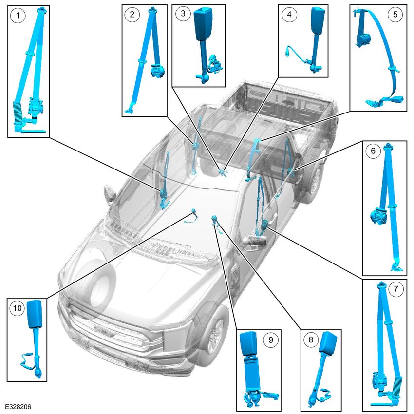
1-4                                                                                                                           General Information

                                 Section 1: General Information

New Vehicle Storage — Tires
The following steps should be taken to avoid flat spotting when the vehicle is not used for a period of time.

•     Keep the vehicles tire pressure at the recommended operating pressure.
•     If the vehicle is stored for a period longer than 15 days, it should be moved several feet during each 15-day period. The vehicle should be
      parked after being moved so that a different portion of the tread contacts the ground.

Vehicle Storage — Electrical

NOTICE:
If your vehicle is to be stored for 30 days or longer, the low voltage (trunk) battery negative terminal must be disconnected. Failure
to do this could damage the battery.

NOTE:
Extended storage time which results in the discharge of the low and/or high voltage batteries, may result in the setting of Diagnostic Trouble
Codes (DTCs) and/or a no-start condition.

To maintain the high voltage battery, once a month the vehicle's high voltage battery should be charged. This will maintain the high voltage
battery, but may not be enough to maintain the 12v (low voltage) battery. Additional low voltage battery charging may be required after 60
days.

•     For FHEV Vehicles, the vehicle should be started and driven to maintain high voltage battery charge.

Tires and Loading
Tire Replacement Requirements

      WARNING:
Only use replacement tires and wheels that are the same size and type (such as P-metric versus LT-metric or all-season versus all-
terrain) as those originally provided by Ford. Use of any tire or wheel not recommended by Ford can affect the safety and
performance of your vehicle, which could result in an increased risk of the loss of vehicle control, vehicle rollover, personal injury
or death. Additionally, the use of non-recommended tires and wheels could cause steering or suspension failure. If you have
questions regarding tire replacement, see an authorized Ford or Lincoln dealer.

NOTICE:
Do not install an off road, aggressive tread or incorrectly sized tire. Any of these may cause elevated stress to the steering system.
This can cause the power steering system to overheat and shut off the power assist, which can affect the safety and performance of
your vehicle.

NOTE:
Vehicles are equipped with a reduced rolling resistance tire design. The use of a different tire can affect the travel distance of the vehicle as
well as the vehicle's fuel economy.

Make sure all tires and wheels on the vehicle are of the same size, type, tread design, brand, load-carrying capacity and speed rating because
it can affect the safety and performance of your vehicle, which could result in an increased risk of loss of vehicle control.

Tire Pressure Monitoring System (TPMS) Principles of Operation
The TPMS monitors the tire pressure using 4 valve stem mounted TPMS sensors to provide accurate tire pressures. Each individual sensor
contains its own battery and transmits tire pressure data to the controlling module every 60 seconds when the vehicle speed exceeds 32 km/h
(20 mph). The TPM module is a radio receiver that collects the tire pressure data and relays the information via the MS-CAN to the BCM. All of
the TPMS functions are controlled by the BCM. The TPMS sensors are trained to the BCM, which records each TPMS sensors unique
identifier. The BCM records where each TPMS sensor is located based on the training order and compares the actual tire pressure with the
desired tire pressure as indicated on the Vehicle Certification label. If the tire pressure deviates from the desired tire pressure the BCM, using
the HS-CAN, signals the IPC to illuminate the TPMS warning indicator and also displays a message on the message center. The programmed
tire pressure cannot be changed.
This vehicle, as delivered by Ford Motor Company, conforms to Standard FMVSS138, Tire Pressure Monitoring Systems.

                                                     2021 F-150 Hybrid Modifiers Guide, 1/2021                    © Copyright Ford 2020 FoMoCo
General Information                                                                                                                          1-5

                                Section 1: General Information

This system may not function if any of the following components are removed, relocated or modified in any way:

•    Original Equipment Manufacturer (OEM) wheels and tires
•    Tire pressure sensors or valve stems
•    Body Control Module (BCM)
•    BCM software and calibrations
•    Tire Pressure Module (TPM)
•    Instrument Cluster (IC) module
•    IC software and calibrations
•    Vehicle wheelbase longer than originally released

Certain modification could cause reduced system performance, up to and including the complete loss of TPM system functionality. This may
include:

•    Non-OEM wheels or tires
•    The addition of steel carcass or run-flat tires
•    Modification of the vehicle recommended tire pressure
•    Lengthening of the vehicle wheelbase may affect signal strength of the sensors to a point where the rear sensors can no longer be heard
     by the TPM module. (Vehicles certified at released wheelbases only)
•    The addition of metallic structures may affect the signal strength of the sensors and could interfere or prevent the TPM module from
     hearing the rear sensors.
•    The addition of intended or unintended transmitters to the vehicle may affect the signal strength of the sensors or interfere with the TPM
     module's antenna

The TPM system as delivered from the Ford Motor Company, complies with part 15 of the FCC rules and with RS-210 of Industry Canada.
Operation is subject to the following 2 conditions:

•    This device may not cause harmful interference, and
•    This device must accept any interference received, including interference that may cause undesired operation.

Using Snow Tires and Traction Devices

NOTE:
Snow tires must be the same size and grade as originally equipped on your vehicle.

The tires on your vehicle have all-weather tread to provide traction in the rain and snow; however, in some climates, using snow tires or
traction devices may be necessary.
Follow these guidelines when using snow tires and traction devices:

•    SAE Class "S" cables should ONLY be used on the vehicle front tires.
•    Install cables or chains securely, verifying that the cables or chains do not touch any wiring or brake lines.
•    Drive cautiously! If you hear the cables or chains rub or bang against the vehicle, stop and retighten them. If this does not work, remove
     the cables or chains to prevent vehicle damage.
•    Avoid overloading your vehicle.
•    Remove the cables or chains when they are no longer needed. Do not use cables or chains on dry roads.
•    Do not exceed 48 km/h (30 mph) with tire cables or chains on your vehicle.

Consult your dealer for information on other Ford approved methods of traction control.

                                                   2021 F-150 Hybrid Modifiers Guide, 1/2021                   © Copyright Ford 2020 FoMoCo
1-6                                                                                                                        General Information

                                 Section 1: General Information

Vehicle Loading

      WARNING:
The appropriate loading capacity of your vehicle can be limited either by volume capacity (how much space is available) or by
payload capacity (how much weight the vehicle should carry). Once you have reached the maximum payload of your vehicle, do not
add more cargo, even if there is space available. Overloading or improperly loading your vehicle can contribute to the loss of
vehicle control and vehicle rollover.

      WARNING:
Exceeding the Safety Compliance Certification Label axle and/or vehicle weight rating limits could result in substandard vehicle
handling or performance, engine, transmission and/or structural damage, serious damage to the vehicle, loss of control and
personal injury.

Gross vehicle weight rating (GVWR) is the maximum allowable weight of the fully loaded vehicle (including all options, equipment, passengers
and cargo). The GVWR is shown on the Safety Compliance Certification Label located on the B-pillar or the edge of the driver's door.
Gross axle weight rating (GAWR) is the maximum allowable weight that can be carried by a single axle (front or rear). These numbers are
shown on the Safety Compliance Certification Label located on the B-pillar or the edge of the driver's door. The total load on each axle must
never exceed its GAWR.

      WARNING:
Do not use replacement tires with lower load carrying capacities than the original tires because they may lower the vehicle's gross
vehicle weight rating (GVWR) and gross axle weight rating (GAWR) limitations. Replacement tires with a higher limit than the
originals do not increase the GVWR and GAWR limitations.

Steps for determining the correct load limit:

•     Locate the statement "The combined weight of occupants and cargo should never exceed XXX kg or XXX lb" on your vehicle's placard.
•     Determine the combined weight of the driver and passengers that will be riding in your vehicle.
•     Subtract the combined weight of the driver and passengers from XXX kg or XXX lb.
•     The resulting figure equals the available amount of cargo and luggage load capacity. For example, if the "XXX" amount equals 1,400 lb
      and there will be five 150 lb passengers in your vehicle, the amount of available cargo and luggage load capacity is 650 lb (1400 - 750 (5
      x 150) = 650 lb). In metric units (635 - 340 (5 x 68) = 295 kg).
•     Determine the combined weight of luggage and cargo being loaded on the vehicle. That weight may not safely exceed the available
      cargo and luggage load capacity calculated in the step above.

Ambient Temperature Change and Tire Pressure

NOTICE:
Do not inflate tire higher than maximum pressure stamped on tire sidewall. Premature tire wear or damage to the tire may result.

Tire pressures fluctuate with temperature changes. For this reason, tire pressure must be set to specification when tires are at outdoor
ambient temperatures. If the vehicle is allowed to warm up to shop temperatures, and the outside temperature is less than shop temperature,
the tire inflation pressure must be adjusted accordingly.
If the tires are inflated to specification at shop temperatures, and the vehicle is moved outdoors when the outdoor ambient temperature is
significantly lower, the tire pressure may drop enough to be detected by the TPM system and activate the TPM system warning lamp.
As the ambient temperature decreases by 6°C (10°F), tire pressure decreases 7 kPa (1 psi). Adjust the tire pressure by 7 kPa (1 psi) for each
6°C (10°F) ambient temperature drop as necessary to keep the tire at the specified vehicle certification label pressure. Refer to the following
tables to adjust the tire pressure indoors for colder outside temperatures.

                                                    2021 F-150 Hybrid Modifiers Guide, 1/2021                  © Copyright Ford 2020 FoMoCo
General Information                                                                                                                              1-7

                                  Section 1: General Information

Ride Height Measurement — Front
1.   NOTE:
     Make sure that the vehicle is positioned on a flat, level surface and the tires are inflated to the correct pressure. Vehicle should have a full
     tank of fuel.

     Jounce front and rear suspension vigorously to allow the vehicle to settle.
2.   Before measuring ride height check:
     a.   Tires are inflated to the correct pressure.
     b.   Vehicle should have at least one-half tank of fuel.
     c.   All fluids at proper levels.
     d.   No cargo inside the cab or bed.
     e.   Inspect for aftermarket equipment. Check for aftermarket changes to the steering, suspension, wheel and tire components (such as
          competition, heavy duty, etc.).

                                                        2021 F-150 Hybrid Modifiers Guide, 1/2021                 © Copyright Ford 2020 FoMoCo
1-8 General Information
Section 1: General Information
3. Ride height = 2–3 (Use the General Equipment: Surface Gauge)
• easure the distance between the flat level surface and the center of the rearward lower arm bolt. (measurement 2).
M
•Measure the distance between the flat level surface and the lowest point on the wheel knuckle. (measurement 3).
Use the General Equipment: Surface Gauge
4. With the surface gauge positioned on a flat, level surface, record the measurement of the surface gauge position (measurement 2) and
(measurement 3).
5. Subtract measurement 3from measurement 2 to obtain the front ride height.
2021 F-150 Hybrid Modifiers Guide, 1/2021 © Copyright Ford 2020 FoMoCoGeneral Information 1-9
Section 1: General Information
Ride Height Measurement — Rear
1. NOTE:
Make sure that the vehicle is positioned on a flat, level surface, transmission in the PARK position and the parking brake OFF.
Jounce front and rear suspension vigorously to allow the vehicle to settle.
2. Before measuring ride height check:
a. Tires are inflated to the correct pressure.
b. Vehicle should have at least one-half tank of fuel.
c. All fluids at proper levels.
d. No cargo inside the cab or bed.
e. Inspect for aftermarket equipment. Check for aftermarket changes to the steering, suspension, wheel and tire components (such as
competition, heavy duty, etc.).
3. NOTE:
If equipped with monotube rear shock absorbers, adjust +8mm to rear ride height nominal.
Measure the distance between the top of the rear axle tube (item 3) and the rear axle jounce stop (item 2) to obtain the rear ride height
(item 1) (Use the General Equipment: Surface Gauge)
2021 F-150 Hybrid Modifiers Guide, 1/2021 © Copyright Ford 2020 FoMoCo1-10 General Information
Section 1: General Information
Ride Height Specifications
Item Specification
Ball Joint Deflection
Lower 0-0.8 mm (0-0.032 in)
Upper 0-0.2 mm (0-0.008 in)
Front Ride Height
Front Ride Height 120 mm (4.803 in) ± 12 mm (0.472 in)
Rear Ride Height 165 mm (6.496 in) ± 12 mm (0.472 in)
Side-to-Side Lean (All Vehicles)
Front — maximum 7 mm (0.276 in)
Rear — maximum 8 mm (0.315 in)
2021 F-150 Hybrid Modifiers Guide, 1/2021 © Copyright Ford 2020 FoMoCoSECTION 2: Electrical
Table of Contents
Contents PAGE
Section 2: Electrical ...................................................................................................................................................................... 2-2
High Voltage Battery Depowering ........................................................................................................................................... 2-2
High Voltage Battery Depowering using FDRS ...................................................................................................................... 2-3
Manual De-Energizing ............................................................................................................................................................ 2-4
Electrical Basics ...................................................................................................................................................................... 2-6
General Electrical Considerations .......................................................................................................................................... 2-6
Electrical Systems Management ............................................................................................................................................ 2-8
Vehicle Component Electrical Loads ...................................................................................................................................... 2-8
General Guidelines ................................................................................................................................................................. 2-9
Splices and Repairs .............................................................................................................................................................. 2-14
Wiring Reference Information ............................................................................................................................................... 2-19
2021 F-150 Hybrid Modifiers Guide, 1/2021 © Copyright Ford 2020 FoMoCo2-2 Electrical
Section 2: Electrical
Section 2: Electrical
High Voltage Battery Depowering
WARNING:
THE HIGH-VOLTAGE SYSTEM MAY RETAIN A DANGEROUS LEVEL OF VOLTAGE FOR A SHORT TIME AFTER THE SERVICE
DISCONNECT HAS BEEN OPENED. WAIT 5 MINUTES FOR THE VOLTAGE TO DISSIPATE BEFORE BEGINNING SERVICE. FAILURE
TO FOLLOW THIS INSTRUCTION MAY RESULT IN SERIOUS PERSONAL INJURY OR DEATH.
WARNING:
REMOVING THE BATTERY HIGH VOLTAGE SERVICE DISCONNECT DOES NOT DISSIPATE VOLTAGE INSIDE THE BATTERY PACK.
THE BATTERY PACK REMAINS LIVE AND DANGEROUS. CONTACT WITH THE HIGH VOLTAGE BATTERY PACK INTERNALS MAY
RESULT IN SERIOUS PERSONAL INJURY OR DEATH.
WARNING:
ELECTRIC VEHICLES DAMAGED BY A CRASH MAY HAVE COMPROMISED HIGH VOLTAGE SAFETY SYSTEMS AND PRESENT A
POTENTIAL HIGH VOLTAGE ELECTRICAL SHOCK HAZARD. EXERCISE CAUTION AND WEAR APPROPRIATE PERSONAL
PROTECTIVE EQUIPMENT (PPE) INCLUDING HIGH VOLTAGE SAFETY GLOVES AND BOOTS. REMOVE ALL METALLIC JEWELRY,
INCLUDING WATCHES AND RINGS. ISOLATE THE HIGH VOLTAGE SYSTEM AS DIRECTED BY THE FORD EMERGENCY
RESPONSE GUIDE FOR THE VEHICLE. FAILURE TO FOLLOW THESE INSTRUCTIONS MAY RESULT IN SERIOUS PERSONAL
INJURY OR DEATH.
WARNING:
TO PREVENT THE RISK OF HIGH-VOLTAGE SHOCK, ALWAYS FOLLOW PRECISELY ALL WARNINGS AND SERVICE
INSTRUCTIONS INCLUDING INSTRUCTIONS TO DEPOWER THE SYSTEM. THE TOTAL VOLTAGE OF THE VEHICLE HV BATTERY
PACK MAY BE UP TO APPROXIMATELY 450 VOLTS DC. THIS VOLTAGE IS PROVIDED THROUGH HIGH-VOLTAGE CABLES TO ITS
COMPONENTS AND MODULES. THE HIGH-VOLTAGE CABLES AND WIRING ARE IDENTIFIED BY ORANGE HARNESS TAPE OR
ORANGE WIRE COVERING. ALL HIGH-VOLTAGE COMPONENTS ARE MARKED WITH HIGH-VOLTAGE WARNING LABELS WITH A
HIGH-VOLTAGE SYMBOL. FAILURE TO FOLLOW THESE INSTRUCTIONS MAY RESULT IN SERIOUS PERSONAL INJURY OR
DEATH.
WARNING:
SERVICE OF THE HIGH VOLTAGE SYSTEM ON THIS VEHICLE IS RESTRICTED TO QUALIFIED PERSONNEL. THE REQUIRED
QUALIFICATIONS VARY BY REGION. ALWAYS OBSERVE LOCAL LAWS AND LEGISLATIVE DIRECTIVES REGARDING ELECTRIC
VEHICLE SERVICE. FAILURE TO FOLLOW THIS INSTRUCTION MAY RESULT IN SERIOUS PERSONAL INJURY OR DEATH.
WARNING:
DISCONNECT THE 12V BATTERY BEFORE SERVICING THE DIRECT CURRENT TO ALTERNATING CURRENT (DC-AC) INVERTER
OR ALTERNATING CURRENT (AC) POWERPOINT TO PREVENT THE RISK OF HIGH VOLTAGE SHOCK. FAILURE TO FOLLOW THIS
INSTRUCTION MAY RESULT IN SERIOUS PERSONAL INJURY.
NOTICE:
Do not backprobe, splice or repair the high voltage (orange) wiring. Voltage in the system is approximately 450 volts DC. Damage
may occur to equipment added to the system.
NOTICE:
None of the High Voltage Traction Battery (HVTB) wiring should be tapped or spliced to check for battery voltage (power), ground
or signals.
NOTICE:
Modification of Low-Voltage (LV) power & control wires connecting to the High-Voltage (HV) battery system can damage or disable
the HV Battery system. Do not open or modify High Voltage battery pack
Throughout a vehicle, electricity is supplied through "hot" wires, comparable to the pressurized supply pipes of a plumbing system. At various
points along the wires are electrical loads in the form of lights, switches and receptacles. Turning on a light switch is somewhat like opening a
faucet to let water run; electricity flows through the hot wire to make the light illuminate. Once the electricity has done its work, its potential
drops to zero, just as water loses pressure after flowing through a sink or laundry tub. The electrical system has drains, which are the ground
wires that return the electricity to its source, just as a plumbing system has drain pipes through which water runs into the sewer mains or
ground.
2021 F-150 Hybrid Modifiers Guide, 1/2021 © Copyright Ford 2020 FoMoCoElectrical 2-3
Section 2: Electrical
The lights or equipment, technically called the load, can be compared to a water wheel that remains motionless until a stream of water causes
it to turn. A load consists of a resistance, a material that permits the passage of electricity, but only with difficulty and thereby creates heat.
Resistance to electricity flowing through a wire can be compared to the resistance given to water flowing through a hose, as if the hose were
to be squeezed, it would restrict the flow of water. A load may also be inductive, typically a motor with windings of copper wire, in which the
magnetic fields generated by the electrical current creates motion. The tungsten filament of an incandescent bulb or the heating element of an
electric heater in a coffee pot would be an example of a resistive load. At any moment, the demand on an electrical system depends on the
number of loads in operation and their consumption of energy, just as demands on a water system depend on how many faucets are opened
and how wide they are opened.
The mechanics and physical fittings of the system are simple. Electricity moves throughout the vehicle in wires of different sizes, according to
the electricity a circuit may have to carry.
Electrical Terms
VOLT is the unit of electrical potential, equal to the difference of electrical potential between 2 points in a circuit. It could be compared to the
pressure, or the push, on the water to move it through a pipe.
AMPERE or AMPS is the unit used to measure the amount of electrical flow; the number of electrically charged particles called electrons that
flow past a given point in a circuit. It is similar to measuring the amount of water flowing through a pipe at any given point. The larger the pipe
is, the more water that can flow past one given point per second. Similarly, the bigger the wire is, the more electricity that can flow past a given
point.
WATT is the unit of power. It indicates the rate at which a device converts electric current to another form of energy, either heat or motion. Or
to put it another way, the rate at which a device converts energy.
The relationship of volts, amperes and watts to one another is expressed in a simple equation that enables you to make any calculations you
may need for proper and safe electrical modifications to the vehicle. Volts x Amps = watts. If the current is at 12 volts and a device requires 4
amperes of current, the equation will read 12 volts x 4 amperes = 48 watts.
To figure the current needed for a device rated in watts, turn the equation around: Watts/volts = amperes. For example, if you have a piece of
equipment, such as a communications radio, that uses 120 watts: 120 watts/12 volts = 10 amperes.
High Voltage Battery Depowering using FDRS
WARNING:
Before beginning any service procedure in this manual, refer to health and safety warnings in Workshop Manual (WSM) Section
100-00 General Information. Failure to follow this instruction may result in serious personal injury.
WARNING:
To prevent the risk of high-voltage shock, always follow precisely all warnings and service instructions, including instructions to
depower the system. The high-voltage system utilizes approximately 450 volts DC, provided through high-voltage cables to its
components and modules. The high-voltage cables and wiring are identified by orange harness tape or orange wire covering. All
high-voltage components are marked with high-voltage warning labels with a high-voltage symbol. Failure to follow these
instructions may result in serious personal injury or death.
1. Using the FDRS CARRY OUT the High Voltage System De-energizing routine and follow the on-screen instructions.
2. Release the Connector Position Assurance (CPA) clip.
2021 F-150 Hybrid Modifiers Guide, 1/2021 © Copyright Ford 2020 FoMoCo2-4 Electrical
Section 2: Electrical
3. NOTE:
The tab must be depressed prior to pushing the connector back in or damage to the connector may result.
Depress the tab while pulling the connector until the hole is completely visible on the top of the connector.
4. Insert a suitable tool inside the connector hole to prevent the connector from closing.
5. Using the FDRS COMPLETE the High Voltage System De-energization routine and verify the High Voltage System has been de-
energized.
2021 F-150 Hybrid Modifiers Guide, 1/2021 © Copyright Ford 2020 FoMoCoElectrical 2-5
Section 2: Electrical
Manual De-Energizing
WARNING:
To prevent the risk of high-voltage shock, always follow precisely all warnings and service instructions, including instructions to
depower the system. The high-voltage system utilizes approximately 450 volts DC, provided through high-voltage cables to its
components and modules. The high-voltage cables and wiring are identified by orange harness tape or orange wire covering. All
high-voltage components are marked with high-voltage warning labels with a high-voltage symbol. Failure to follow these
instructions may result in serious personal injury or death
WARNING:
Before beginning any service procedure in this manual, refer to health and safety warnings in WSM Section 100–00 General
Information. Failure to follow this instruction may result in serious personal injury.
NOTICE:
Manual De-energization should only be performed when a Ford-specific diagnostic tool is not available.
NOTICE:
To prevent the risk of high voltage shock, the high voltage battery cover must not be removed if any of the following condition exist:
• BECM DTC P0AA6:00 that has been diagnosed to be an internal fault with the high voltage Battery.
• BECM Diagnostic Trouble Codes (DTCs) P0AA1:00 AND P0AA4:00 are present.
• BECM Diagnostic Trouble Codes (DTCs) P0AA1:00 AND P0DOF:00 are present (PHEV only).
1. Turn the ignition ON without depressing the brake pedal (Accessory mode).
2. NOTE:
A scan tool that is capable of performing a self-test on the BECM is required.
Using a scan tool perform BECM self test and record the Diagnostic Trouble Codes (DTCs).
• If BECM Diagnostic Trouble Codes (DTCs) P0AA1:00 ANDP0AA4:00 are present. Refer to WSM procedures in section 414-03 High
Voltage Battery, Mounting and Cables, Diagnosis and Testing.
3. Turn the ignition OFF.
4. Release the Connector Position Assurance (CPA) clip.
5. NOTE:
The tab must be depressed prior to pushing the connector back in or damage to the connector may result.
Depress the tab while pulling the connector until the hole is completely visible on the top of the connector.
2021 F-150 Hybrid Modifiers Guide, 1/2021 © Copyright Ford 2020 FoMoCo2-6 Electrical
Section 2: Electrical
6. Insert a suitable tool inside the connector hole to prevent the connector from closing.
7. Disconnect the low voltage electrical connector at the High Voltage Battery.
8. Disconnect the high voltage electrical connector at the High Voltage Battery.
9. Wait a minimum of 5 minutes.
Electrical Basics
WARNING:
BEFORE CARRYING OUT ANY VEHICLE MODIFICATIONS, THE HIGH-VOLTAGE TRACTION BATTERY (HVTB) MUST BE
DEPOWERED. FAILURE TO FOLLOW THESE INSTRUCTIONS MAY RESULT IN SEVERE PERSONAL INJURY OR DEATH.
Control Modules — Red Area
Do not install any components into the control modules or module harness. Connecting into this system may affect control module operation.
For example, connecting of aftermarket electrical equipment into the brake light circuit or any other circuit which is connected to the PCM, anti-
lock brake computer, air bag system or any other vehicle system will cause vehicle malfunction.
Controller Area Network (CAN) Bus
NOTICE:
Wiring faults in the controller area network (CAN) bus may shut down the vehicle and prevent further operation.
Do not splice or connect any equipment to the controller area network (CAN) bus wiring.
2021 F-150 Hybrid Modifiers Guide, 1/2021 © Copyright Ford 2020 FoMoCoElectrical 2-7
Section 2: Electrical
General Electrical Considerations
Communication Equipment
Mobile communication systems may harm the operation of the vehicle, particularly if they are not properly designed for automotive use or are
not properly installed. Citizen band (CB) transceivers, garage door openers and other transmitters whose power output is 5 watts or less will
not ordinarily affect the operation of the vehicle.
Vehicle Speed Signal
The vehicle speed signal is sent from the BCM to other vehicle modules through the CAN bus. There is a specific wire/circuit that carries the
vehicle speed signal pulses.
Disabling Brake Lights
Do not disable the brake light circuits for any reason.
12 Volt Battery
The 12 volt battery is a standard automotive battery. It is a DC source connected in a negative ground system. The battery case is sealed, with
2 vent holes to release gases. The battery has 3 major functions:
• Storage of electricity for later use
• Voltage stabilizer for the electrical system
• Temporary power source when electrical loads exceed the DC/DC converter output current
High and Low-Voltage Systems
NOTICE:
Do not backprobe or splice into the high-voltage system. The total voltage of the vehicle HV battery pack may be up to
approximately 450 volts DC. Damage may occur to equipment added to the system.
High-Voltage Traction Battery (HVTB)
NOTICE:
None of the high-voltage traction battery (HVTB) wiring should be tapped or spliced to check for battery voltage (power), ground or
signals.
NOTICE:
Modification of low-voltage (LV) power & control wires connecting the high-voltage (HV) battery system can damage or disable the
HV Battery system. Do not open or modify High Voltage battery pack
The high-voltage traction battery (HVTB) is a high voltage DC source connected in a floating ground system. The battery receives, stores and
delivers high-voltage electrical power when required by the vehicle control strategy. On the HVTB there is 1 controller, a battery energy control
module (BECM). There is also the High Voltage Battery Junction Box (HVBJB) which houses the contactors, current sensor and the
associated components. The service disconnect is located under hood and is used to disconnect the high-voltage from the vehicle system.
Always de-energize the High Voltage system prior to servicing a vehicles High Voltage componet.
DC/DC Converter
The DC/DC converter is a liquid-cooled component that converts high-voltage DC power to low-voltage DC power. It is a module located in the
engine compartment and maintains an electrical isolation between the 2 DC power systems. This system converts the high-voltage
(approximately 450 volts) to low-voltage (12 volts) that provides power to the vehicle low-voltage battery systems. The PCM controls the
operation of the DC/DC converter through an enabled input from the PCM to the DC/DC converter.
Auxiliary Power Point — 12V
NOTICE:
Power outlets are designed for accessory plugs only. Do not insert any other object in the power outlet as this will damage the
outlet and blow the fuse. Do not hang any type of accessory or accessory bracket from the plug. Improper use of the power outlet
can cause damage not covered by your warranty.
NOTE:
Do not use the power point for operating the cigarette lighter element (if equipped).
To prevent the fuse from being blown, do not use the power point(s) over the vehicle capacity of 12-VDC/180W.
To prevent the battery from being discharged, do not use the power point longer than necessary when the engine is not running.
2021 F-150 Hybrid Modifiers Guide, 1/2021 © Copyright Ford 2020 FoMoCo2-8 Electrical
Section 2: Electrical
Generator Output
The generator for the hybrid vehicles are different from those used on the non-hybrid models. The non-hybrid vehicles have a 110-amp
generator.
Electrical Systems Management
Care must be given in deciding what equipment should be installed into a vehicle given the power demands of the equipment and the power
available from the vehicle. Develop a power load strategy to minimize the risk of running out of power. Examine the proposed equipment for
vehicle installation. Add up the current requirements. If the current requirements exceed what the vehicle can reasonably be expected to
provide, the battery begins discharging to provide the power to the equipment that the generator is unable to provide. After some period of
time, the vehicle shuts off as the battery voltage decreases to a level that cannot sustain vehicle operation.
There are alternatives that can be considered to minimize system electrical overload. Consider the current requirements of equipment before it
is purchased and installed. For example, modern light bars and radios use a fraction of the current than units made as recently as 1996. The
light bar is the most power intensive unit installed on most vehicles, considerable attention should be given to its current requirement.
Changes in driver habits can make a difference in the electrical system load and will impact available power as well. When a vehicle is sitting
and no one is in the car, certain electrical equipment can be turned off until the driver is ready to get back into the vehicle.
Vehicle Component Electrical Loads
Vehicle component electrical loads are shown in the table below. Not all features are powered all the time, so actual vehicle loads on the
power supply system will vary.
NOTE:
The electric A/C compressor loads are included with the blower loads.
Component Amps
Base
Miscellaneous base loads 16.5
Cooling
Cooling fan (high speed variable) 27.0
Climate Control
A/C fan to face — high speed (recirculating air) 25.0
A/C fan to face — M/H speed (recirculating air) 16.0
Heater fan to foot — M/H speed (fresh air) 16.0
Lighting
Exterior and instrument panel lamps (non-dimmable) 3.5
Headlamps — low beam 9.1
Brake lights (with CHMSL) 5.1
Heated Features
Heated rear window (includes heated mirrors) 18.0
Heated front seat — LH 4.5
Heated front seat — RH 4.5
Other
Radio 4.0
Typical Vehicle Load = 95-110 Amps
Typical Taxi Equipment
Loads for equipment commonly found on taxi vehicles are shown in the table below. Not all equipment will be operating at the same time, so
actual loads on the power supply system will vary.
2021 F-150 Hybrid Modifiers Guide, 1/2021 © Copyright Ford 2020 FoMoCoElectrical 2-9
Section 2: Electrical
Component Amps
Communications radio 5.0-20.0
Light bar 28.0-43.0
LED light bar 6.0
Taximeter 3.3
Receipt printer 3.0
Camcorder 2.0
General Guidelines
• Do not open or modify the High Voltage Battery pack or any High Voltage Components.
• Do not modify the cooling system. High-voltage vehicle components may be damaged if any cooling system modifications are attempted.
• Do not backprobe, splice or repair the high-voltage system (orange) wiring/cables.
• Do not mount to or modify the high-voltage system (orange) wiring/cables in any way.
• Do not cut, weld or screw into the High Voltage Battery pack or any High Voltage Components case or penetrate the batteries in any
way.
• Air bag restraint systems must remain intact as received from Ford Motor Company. Before modifications are done to the vehicle, the
system must be depowered by following the instructions provided in the current Workshop Manual.
• Provide circuit protection (fuses) for all wiring. The fuse rating should not exceed either the rated wiring current capacity or the total
current requirements for all the add-on components on the circuit. Install fuses as close to the point of tapped power as possible.
• Provide protective covering in all areas that could be damaged during normal equipment installations.
• Do not allow control panels attached to the instrument panel to protrude into the driver and passenger air bag deployment zones. For
additional information, refer to Section 4: Reference in this guide.
• Do not install switches and gauges in the driver or passenger knee impact areas.
• Provide adequate retention for wiring harnesses so they are clear of bolts, corners or edges which could abrade the wires during normal
vehicle operation.
• Properly secure all wiring relocated or removed while working behind the instrument panel to prevent chafing, squeaks and rattles.
• Anticipate misrouted wiring situations and protect all wiring from penetration by screws and raw edges.
• Weather-seal all electrical connectors exposed to the elements.
• Do not use quick splice connectors or wire nuts.
• Install the fuse panel so fuses are readily accessible.
• Make sure that connections are easily accessible for assembly and service.
• Inspect all Ford gauges, lights and switches for correct operation after instrument panel work is performed.
• Make sure submersible connectors do not lose their seals under extreme assembly conditions such as bending wires 90 degrees
immediately after the connector.
• Whenever using connectors, use a socket (female) connector on the electrical source side and a plug (male) connector on the electrical
load side to reduce the possibility of a short circuit when disconnected.
• Adherence to the above guidelines is not to be construed as approval by Ford Motor Company of any specific revisions or additions to
the vehicles original electrical system.
• Document all revisions to the electrical system and place with the vehicle Owner's Literature. Color code and/or label all revisions or
additions to wiring.
• Disconnect the negative battery cable of vehicles stored on-site to reduce the possibility of draining the battery by lights or other
equipment.
Keep-Alive Memory (KAM) Power
The electronic motor and/or transmission control modules and the High Voltage Battery pack BECM require low battery voltage (12 volts) to be
supplied at all times to maintain the keep-alive memory (KAM). Keep this in mind when installing load disconnect switches or solenoids.
Equipment Grounding Guidelines
NOTICE:
Do not use/modify any of the high-voltage system grounds or damage to the high-voltage components may occur.
• Do not ground the body to the transmission or transmission crossmember. Ground accessories to the chassis or the vehicle battery.
• Splicing into circuitry relating to the electronic engine and/or transmission control systems is not acceptable because of the adverse effect
on the electronic system operation.
• Adequately protect electrical connections exposed to the elements.
2021 F-150 Hybrid Modifiers Guide, 1/2021 © Copyright Ford 2020 FoMoCo2-10 Electrical
Section 2: Electrical
Wire Insulation
• Polyvinyl chloride (PVC) rated at 90°C (194°F) is the standard wire insulation acceptable for inside body use but is not acceptable for
underhood/underbody wiring.
• Hypalon insulation should be used on links only (Ford specification ESB-M1L54-A).
• Cross-linked polyethylene (XPLPE or SXL) rated at 125°C (257°F) is the required insulation for underhood/underbody applications (Ford
specification ESB-M1L123-A).
• GXL can be used as an alternate wire (Ford specification ESB-M7L85B) as long as the concentricity specifications are met. To provide a
water-resistant seal in conjunction with crimp connectors, a Duraseal® crimp connector is recommended since it is designed to account
for outside wire diameter that is smaller than the present SXL wire.
Terminals and Connectors
Connector Types:
• Submersible (sealed) — A connector that is capable of being immersed in water.
• Weather-resistant — A connector that will retain its sealing and connection qualities while being exposed to adverse weather conditions.
• Duraseal® crimp — A supplier trade name for a sealed wiring repair or splice.
When a connection is not defined (typical situation — harness-to-harness connectors), the following suggestions should be implemented:
• Determine the connector type. If it will be located in a hostile environment, use a sealed connector; if not, use an open connector. A
hostile environment is defined as being exposed to water and/or salt accumulation and/or high temperatures (that is; underhood, exterior
panels and footwells). Use in-line connectors with secondary locks to prevent the terminal from being pushed out.
— Do not use single wires smaller than 14 gauge in a 2-way or larger weather-resistant connector (the very large style), since the wire may
break during disengagement.
— Use Hypalon, XLPE or Elexar insulation in submersible connectors to maintain sealing integrity. PVC is not acceptable because its
properties allow it to set in a deformed pattern, therefore compromising the integrity of the seal.
• Determine the terminal type. Base your decision on wire gauge, current carrying capacity, connector type and insulation type.
— Use non-detent low insertion force terminals whenever possible.
— Do not use low insertion force female terminals in weather-resistant connectors.
— Analyze circuit requirements (signal levels, current, voltage) to determine the proper plating material (such as gold). Use of non-plated
terminals is not recommended.
— Do not use plugs to seal holes in micropin connector grommets. It is very easy to forget to insert them during manufacturing and ruin the
seal. Use a grommet with only the necessary number of holes or use dummy wires at least 600 mm (24 in) long.
— Fully align connectors prior to terminal connection — terminal cavities should have minimum tolerance to prevent terminals from floating,
bending or pin push-out during mating/engagement.
— Make sure connectors of similar type and color are identifiable to the operator to eliminate crossed connections and minimize assembly
time. Avoid using similar types and colors of connectors close together.
— Be sure that connectors have positive locking devices that allow easy installation with a low insertion force and easy removal. The
connector snap should be easily felt and heard.
— Eliminate the use of edgeboard, tang-type and molded-over connectors. The use of blade-type weather-resistant connectors is restricted
to high-current applications which cannot be handled by submersible connectors.
Circuit Protection and Electrical Load
• Modification to the vehicles existing low-voltage (12 volts) wiring should be done only with caution and careful consideration of effects on
the completed vehicles electrical system. Anticipated circuitry should be studied to determine the required circuit protection and to avoid
feedback loops.
• Added circuitry must be protected either by a base vehicle fuse or circuit breaker, or by a similar device supplied by the modifier.
• When adding loads to a base vehicle-protected circuit, make sure the total electrical load through the base vehicle fuse or circuit breaker
is less than the devices load rating.
• Use 80% of the fuse rating to determine maximum steady state load to reduce nuisance fuse failures.
• Use 135% of the fuse rating when sizing wiring to protect the circuit in the event of an overload. Fuses will last for one hour at 135% of
their rating.
— Total current draw is the sum of the base vehicles circuit current requirement (measured with an ammeter) and the anticipated add-on
component current requirements.
— Never increase the rating of a factory installed fuse or circuit breaker.
— If the total electrical load including additional electrical components, on any circuit, is less than the fuse protection rating or the capacity of
some limiting component (switch, relay), the items to be added can be connected directly to that circuit. The headlamp switch circuits
should never have additional lighting or electrical components directly connected.
2021 F-150 Hybrid Modifiers Guide, 1/2021 © Copyright Ford 2020 FoMoCoYou can also read