Zyla sCMOS - Hardware Guide Covers Zyla 4.2 PLUS and 5.5 models with Camera Link or USB 3 connections and air or water cooling - Oxford Instruments
←
→
Page content transcription
If your browser does not render page correctly, please read the page content below

8.2 x 8.2 mm / 512 x 512 sensor
                                  Lowest Noise Imaging EMCCD

                Zyla sCMOS
                               Version 2.0 rev 18 Feb 2021

               Hardware Guide
            Covers Zyla 4.2 PLUS and 5.5 models with
              Camera Link or USB 3 connections and
                                  air or water cooling

andor.com                  © Andor Technology 2021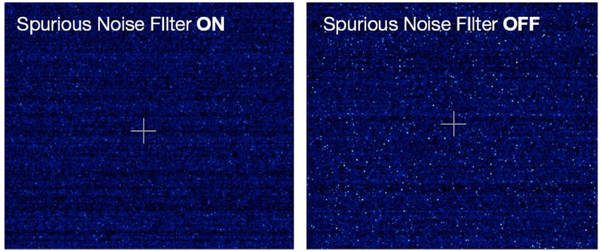
SECTION 1: INTRODUCTION............................................................................................................. 8
1.1		Help and Technical Support..........................................................................................................................9
1.2		Disclaimer.............................................................................................................................................................. 10
1.3		Trademarks and Patent Information.................................................................................................... 10
1.4		Components.......................................................................................................................................................... 11
      1.4.1        Accessories................................................................................................................................................................................. 11
1.5		Power And Signal Connections.................................................................................................................12
      1.5.1        Power Supply Unit (PSU) ................................................................................................................................................. 12
      1.5.2        Connectors.................................................................................................................................................................................. 13
      1.5.3        Multi I/O Timing Cable Pin Outs................................................................................................................................. 13
      1.5.4        Impedance Information.................................................................................................................................................... 14
      1.5.5        Other Connections................................................................................................................................................................. 14
1.6		Cooling Hose Connectors (Water Cooled Models only)...........................................................15
      1.6.1        Important Considerations when using Cooling Systems........................................................................ 15
SECTION 2: FEATURES AND FUNCTIONALITY................................................................... 16
2.1
    sCMOS Structure and Operation..............................................................................................................16
2.2		Rolling and Global Shutter ..........................................................................................................................17
      2.2.1        Rolling Shutter.......................................................................................................................................................................... 18
      2.2.2        Global Shutter (Zyla 5.5 only)....................................................................................................................................... 19
      2.2.3        Selecting Rolling or Global Shutter.......................................................................................................................... 20
           2.2.3.1             Examples of Typical Applications for Global Shutter Mode	�������������������������������������������������� 20
      2.2.4        Rolling and Global Shutter Mechanisms............................................................................................................. 21
2.3		Understanding Read Noise in sCMOS.................................................................................................22
      2.3.1        Spurious Noise Filter............................................................................................................................................................ 23
      2.3.2        Blemish Correction................................................................................................................................................................ 23
2.4           Dual Amplifier Dynamic Range ...............................................................................................................24
2.5		Sensor Readout Optimization...................................................................................................................26
      2.5.1        Gain Channel Control ........................................................................................................................................................ 26
      2.5.2        Pixel Readout Rate .............................................................................................................................................................. 27
      2.5.3        ROI Sub-Image Settings................................................................................................................................................... 27
2.6           Trigger Modes......................................................................................................................................................28
      2.6.1        Example System Usage of Acquisition Events............................................................................................... 29
      2.6.2        Rolling Shutter Triggering Modes.............................................................................................................................. 30
           2.6.2.1             Timing Parameters and Ext Triggering for Zyla 5.5 	�������������������������������������������������������������������� 31
           2.6.2.2             Timing Parameters and Ext Triggering for Zyla 4.2	��������������������������������������������������������������������� 31
           2.6.2.3             Rolling Shutter Internal Triggering (Non-Overlap Mode) 	�������������������������������������������������������� 32
                                                                                                                                                                                                                 2
version 2.0 rev 18 Feb 2021
2.6.2.4              Rolling Shutter Internal Triggering (Overlap Mode)	��������������������������������������������������������������������������33
          2.6.2.5              Rolling Shutter External / Software Triggering (Non Overlap Mode)..................................35
          2.6.2.6               Rolling Shutter External Exposure Triggering (Non-Overlap Mode) ...................................36
          2.6.2.7               Rolling Shutter External Exposure Triggering (Overlap Mode).................................................37
          2.6.2.8              Rolling Shutter External Start Triggering	���������������������������������������������������������������������������������������������������38
          2.6.2.9              Rolling Shutter Global Clear Internal (Non-Overlap Mode)- Zyla 4.2 only.....................39
          2.6.2.10 Rolling Shutter Global Clear External/Software Triggering (Non-Overlap Mode)
          - Zyla 4.2 Only.........................................................................................................................................................................................40
          2.6.2.11 Rolling Shutter Global Clear External Exposure Triggering (Non-Overlap Mode)
          - Zyla 4.2 Only.........................................................................................................................................................................................41
          2.6.2.12 Rolling Shutter Triggering Constraints.........................................................................................................42
     2.6.3         Global Shutter Triggering Modes (Zyla 5.5 only)...............................................................................................43
          2.6.3.1              Global Shutter Internal Triggering (Non-Overlap Mode)	��������������������������������������������������������������44
          2.6.3.2              Global Shutter Internal Triggering (Overlap Mode)	���������������������������������������������������������������������������46
          2.6.3.3              Global Shutter External/Software Triggering	����������������������������������������������������������������������������������������47
          2.6.3.4               Global Shutter External Exposure Triggering (Non-Overlap Mode).....................................49
          2.6.3.5               Global Shutter External Exposure Triggering (Overlap Mode).................................................50
          2.6.3.6              Global Shutter External Start Triggering	���������������������������������������������������������������������������������������������������51
          2.6.3.7              Global Shutter Triggering Constraints..........................................................................................................52
2.7		ACQUISITION MODES ....................................................................................................................................... 53
     2.7.1         Single Scan.....................................................................................................................................................................................53
     2.7.2         Kinetic Series.................................................................................................................................................................................53
     2.7.3         Accumulate....................................................................................................................................................................................53
     2.7.4         Run Till Abort Acquisition.....................................................................................................................................................53
          2.7.4.1              Live Mode...........................................................................................................................................................................54
     2.7.5         Fast Exposure Switch .............................................................................................................................................................54
     2.7.6         Frame Rate Control .................................................................................................................................................................54
     2.7.7         LightScan PLUS...........................................................................................................................................................................54
          2.7.7.1              Multiple Readout Directions................................................................................................................................54
          2.7.7.2              FlexiScan.............................................................................................................................................................................55

                                                                                                                                                                                                                   3
version 2.0 rev 18 Feb 2021
SECTION 3: INSTALLATION...............................................................................................................56
3.1		Safety Considerations.......................................................................................................................................56
3.2		 Camera Mounting...............................................................................................................................................56
3.3		Coolant Hose Connection and Disconnection (Water Cooled Models)........................... 57
      3.3.1         Coolant Recommendations.............................................................................................................................................. 57
      3.3.2         Connecting the Coolant Hoses...................................................................................................................................... 58
      3.3.3         Disconnecting the Coolant Hoses............................................................................................................................... 58
3.4		Recommended Computer Requirements............................................................................................58
3.5		Installing Software (Solis or SDK3) ..........................................................................................................59
3.6		Installing the Camera Framegrabber Card....................................................................................... 60
3.7		Checking & Setting BIOS options (for PCs not supplied by Andor)...................................... 61
3.8		Software Support................................................................................................................................................. 61
SECTION 4: OPERATION......................................................................................................................62
4.1		Connecting your Camera and Switching it on..................................................................................62
4.2		Using the Lens Mount Adaptors.................................................................................................................63
      4.2.1         C-mount Adaptor...................................................................................................................................................................... 63
      4.2.2         CS-mount Adaptor................................................................................................................................................................... 64
      4.2.3         F-mount Adaptor....................................................................................................................................................................... 64
4.3		Cooling........................................................................................................................................................................65
      4.3.1         Integral Thermal Protection.............................................................................................................................................. 65
      4.3.2         TE Cooling (Air-Cooled Models)..................................................................................................................................... 65
      4.3.3         TE Cooling (Water Cooled Models) ........................................................................................................................... 65
4.4		Emergency Mains Disconnection..............................................................................................................66
SECTION 5: MAINTENANCE..............................................................................................................67
5.1		Regular Checks.....................................................................................................................................................67
5.2		Annual Electrical Safety Checks................................................................................................................67
5.3		Fuse Replacement..............................................................................................................................................67
5.4		Zyla Chamber Design And Service Guidance...................................................................................67
5.5		Cooling Hoses and Connections................................................................................................................68

                                                                                                                                                                                                         4
version 2.0 rev 18 Feb 2021
SECTION 6: TROUBLESHOOTING.................................................................................................... 69
6.1		Camera buzzer does not sound on start-up..........................................................................................69
6.2         Camera is not recognized by PC....................................................................................................................69
6.3		Buzzer sounds continuously.............................................................................................................................69
6.4		Fan not operating as expected.......................................................................................................................69
6.5		Camera does not cool to the required temperature........................................................................69
6.6         Fire, Aux_Out and Arm outputs not functioning correctly..............................................................70
6.7		External Trigger input not functioning correctly..................................................................................70
6.8         Condensation Appearing On Exterior Of Camera (Water Cooled Model)...........................70
6.9         Condensation Effect Noticeable in Images.............................................................................................. 71
APPENDIX A: SPECIFICATIONS...........................................................................................................72
APPENDIX B: MECHANICAL DRAWINGS...................................................................................... 75
APPENDIX C: DEW POINT GRAPH.................................................................................................... 77
APPENDIX D: OTHER INFORMATION..............................................................................................78

                                                                                                                                                          5
version 2.0 rev 18 Feb 2021
SAFETY AND WARNING INFORMATION
           PLEASE READ THIS INFORMATION FIRST BEFORE USING YOUR ZYLA sCMOS CAMERA.

1.   To ensure correct and safe operation of this product, please read this guide before use and keep it in a safe place for
     future reference
2.   If equipment is used in a manner not specified by Andor, the protection provided by the equipment may be impaired
3.   Before using the system, please follow and adhere to all warnings, safety, manual handling and operating instructions
     located either on the product or in this Hardware Manual
4.   The Andor Zyla is a precision scientific instrument containing fragile components. Always handle with care
5.   Do not expose the product to extreme hot or cold temperatures
6.   For air-cooled models, ensure that a minimum clearance of approximately 100 mm (4”) is maintained in front of all
     ventilation slots and the fan inlet
7.   For water-cooled models, ensure that cooling water supply is connected prior to powering the camera.
8.   Do not expose the product to open flames
9.   Do not allow objects to fall on the product
10. Do not expose the product to moisture, wet or spill liquids on the product. Do not store or place liquids on the product. If
    a spillage occurs on the product, switch off power immediately, and wipe off with dry, lint-free cloth. If any ingress has
    occurred or is suspected, unplug mains cable, do not use, and contact Andor service
11. The product contains components that are extremely sensitive to static electricity and radiated electromagnetic
    fields, and therefore should not be used, or stored, close to EMI/RFI generators, electrostatic field generators,
    electromagnetic or radioactive devices, or other similar sources of high energy fields
12. Operation of the system close to intense pulsed sources (e.g. plasma sources, arc welders, radio frequency generators,
    X-ray instruments, and pulsed discharge optical sources) may compromise performance if shielding of the Zyla is
    inadequate
13. This product is not designed to provide protection from ionising radiation. Any customer using this product in such an
    application should provide their own protection
14. The Andor Zyla is for use in research laboratories and other controlled scientific environments
15. This equipment has not been designed and manufactured for the medical diagnosis of patients
16. Use only the power supply cord provided with the system for this unit. Should this not be correct for your geographical
    area contact your local Andor representative
17. Only the correctly specified mains supply and fuse must be used
18. Make sure the electrical cord is located so that it will not be subject to damage
19. There are no user-serviceable parts beyond the specified user accessible areas of the product and the enclosure must
    not be opened. Only authorised service personnel may service this equipment

20. The above label indicates that this unit contains components which are sensitive to and can be damaged by
    electrostatic discharge. When working on a unit which is not enclosed it is necessary to follow anti static precautions to
    ensure damage does not occur.

Regulatory Compliance
             The Zyla 4.2 and Zyla 5.5s CMOS Cameras comply with the requirements of the EU EMC and LV Directives
             through testing to EN 61326-1 and EN 61010-1.
		          This product requires a DC power supply (refer to Section 1.6)

     This product complies with international EMC standards, but please note that this includes a permissible loss of
     performance as allowed by EN 61326 1:2013 and IEC 61326 1:2012 for a defect that rarely occurs during 4 kV
     contact ESD strikes. This issue manifests itself in the worst case as one row experiencing 5 times the typical noise that
     persists for the duration of a kinetic series, but disappears thereafter. This issue is theoretical and has never been seen
     during normal use

                                                                                                                            6
version 2.0 rev 18 Feb 2021
Revision History
     Version            Released                                                Description
        1.0             17 Jul 2012                                             Initial Release
        1.1             29 Oct 2012                                  General minor updates throughout.
                                                            General enhancements to presentation (all Sections)
                                                          Text revised to improve clarity of information (all Sections.
                                        Zyla Components revised to show standard supplied components more clearly (Section 1.5)
        1.2             15 Oct 2013           Additional accessories revised to match current options available (Section 1.5.1)
                                                Additional information added for use for lens mount adaptors (Section 4.2)
                                           Updated timing diagrams and tables for Rolling and Global Shutter Modes (Section 2)
                                           Updated to show 12-bit data range and gain channels options (Sections 2.6 and 2.7)
                                                       Added Information to support the Zyla 4.2 model (all Sections).
        1.3             16 Jan 2014                       Added Rolling Shutter Global Clear modes (Section 2.6)
                                                        Timing data updated to align with current data (Section 2.6)
                                                      Information added for Water Cooled Zyla models (all Sections).
        1.4             13 Feb 2014    Further information on frame rate performance for each model under different shutter and ROI
                                                                        modes added (Section 2.5)
                                                     Updates to include support for Zyla USB 3.0 model (All Sections)
                                        Added new section to cover disabling USB host controller power management (Section 3.7.1)
                                                       Updated frame rates table for USB 3.0 models (Section 2.5)
        1.5             09 Jun 2014
                                                  Updated presentation throughout to match current company branding
                                         Updated Figures 4 (Section 1.6.4), 7( Section 2.1) and 12 (Section 2.4) to enhance quality
                                                 Included updates to show support for Windows 8 (Sections 3.4 and 3.7)
                                      Updated accessories list to show that longer lengths of USB 3.0 cable are available, but not sup-
        1.6             15 Sep 2014
                                                                   plied or verified by Andor (Section 1.5.1)
                                      Updated information for Zyla 5.5 model: low vibration fan (as used in Zyla 4.2) fitted to air-cooled
                                             units from February 2015 onwards, max. Ambient temperature changed to 30oC.
        1.7             03 Feb 2015
                                      Edited Mechanical drawing for water cooled models to show distance from C-mount to camera
                                                                 faceplate when installed is 6mm nominal.
                                                        Revised Rolling Shutter Sections (Section 2.6.2.3 to 2.6.3.12)
        1.8             17 Nov 2015                    Corrected cross-reference to Mechanical Drawings (Section 3.2)
                                                                Mechanical drawings updated (Appendix A)

        1.9             01 Feb 2016    Updated PCI slot for USB Card to x4 or greater- previously was x4 only (Sections 3.4 and 3.6).

                                      Added BIOS options checking and setting for Camera Link models used with non-Andor supplied
       1.10            19 May 2016
                                                                            PCs (Section 3.8).
                                      Added note regarding a potential loss of performance in an ESD strike event (Safety and Warning
       1.11             10 Jun 2016
                                                                                   Section)
                                              Expanded cooling information for water cooled models (Section 3.3, Appendix B)
                                                            Added Emergency power off section (Section 4.5)
       1.12             12 Sep 2017
                                                   Updated software, PCIe cards and PC requirements to current spec.
                                                   Added part numbers for power connector and socket (Section 1.6.5)

       1.13             11 Apr 2019                  Updated USA and Asia-Pacific addresses (page 9) and front cover.

                                      Updated mechanical drawings of back view of USB3, water cooled and Camera Link Zyla vari-
       1.14             13 Jun 2019    ants (Appendix A). Updated back view images of Zyla (Section 1.6.2). Minor updates to format
                                                                              throughout.

       1.15             16 Apr 2020                          Updated China office address, updated front cover.

                                      Added new sections 2.7.7 LightScan PLUS, 5.4 Zyla Chamber Design, Service Guidance and 6.9
        2.0             18 Feb 2021       Condensation Effect Noticeable in Images. Added Appendix A with technical, general,
                                                environmental, and power specifications. Updated branding throughout.

Updates to the Manual
Changes are periodically made to the product and these will be incorporated into new editions of the manual.
Please check for new releases of the manual at: andor.oxinst.com/downloads. If you find an issue in this manual
please contact your customer support respresentative (Section 1.1) with a description of the issue.

                                                                                                                                      7
version 2.0 rev 18 Feb 2021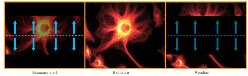
SECTION 1: INTRODUCTION
Thank you for choosing the Zyla Scientific CMOS (sCMOS) camera. You are now in possession of a
revolutionary new sCMOS camera, a breakthrough technology based on the next-generation CMOS image
sensor (CIS) design and fabrication techniques. The camera offers two image sensors of 5.5 Megapixels (Zyla
5.5) and 4.2 Megapixels (Zyla 4.2). It is available in both air cooled, and water cooled forms and with Camera
Link and USB 3.0 connection options.

                              Figure 1: The Zyla sCMOS Camera. Left: Water Cooled model, right: air cooled model

The Zyla sCMOS camera offers:
     •     Extremely low noise
     •     Rapid frame rates
     •     Wide dynamic range
     •     High quantum efficiency (QE)
     •     High resolution
     •     Large field of view

This manual contains useful information and advice to ensure you get the optimum performance from your
new system. If you have any questions regarding your Zyla, camera please feel free to contact Andor directly,
or via your local representative or supplier.

                                                                                                                   8
version 2.0 rev 18 Feb 2021
1.1       Help and Technical Support
If you have any questions regarding the use of this equipment, please contact the representative* from whom
your system was purchased, or:

                                  Europe                                                                 USA
                       Andor Technology Ltd.                                                     Andor Technology
                              7 Millennium Way                                                   300 Baker Avenue
                      Springvale Business Park                                                       Suite # 150
                                  Belfast                                                              Concord
                                 BT12 7AL                                                             MA 01742
                              Northern Ireland                                                            USA
                     Tel. +44 (0) 28 9023 7126                                                Tel. +1 (860) 290-9211
                     Fax. +44 (0) 28 9031 0792                                                Fax. +1 (860) 290-9566

                               Asia-Pacific                                                             China
                     Andor Technology (Japan)                                               Andor Technology (China)

                               5F IS Building                                            Haitong Times Business Center,

                   3-32-42 Higashi-Shinagawa                                                     Building B2 West,

                              Tokyo 140-0002                                           No.11 West Third Ring North Road,

                                   Japan                                                           Haidian District,

                        Tel: +81 3 6732 8968                                                            Beijing,

                        Fax: +81 3 6732 8939                                                           100089
                                                                                                         China
                                                                                            Tel: +86 (0) 10 5884 7900
                                                                                            Fax. +86 (0) 10 5884 7901

* The latest contact details for your local representative can be found on the Contact and Support page of our website.

                                                                                                                           9
version 2.0 rev 18 Feb 2021
1.2 Disclaimer
THE INFORMATION CONTAINED HEREIN IS PROVIDED “AS IS” WITHOUT WARRANTY, CONDITION OR REPRESENTATION OF
ANY KIND, EITHER EXPRESS, IMPLIED, STATUTORY OR OTHERWISE, INCLUDING BUT NOT LIMITED TO, ANY WARRANTY OF
MERCHANTABILITY, NON-INFRINGEMENT OR FITNESS FOR A PARTICULAR PURPOSE.
IN NO EVENT SHALL ANDOR BE LIABLE FOR ANY LOSS OR DAMAGE, WHETHER DIRECT, INDIRECT, SPECIAL, INCIDENTAL,
CONSEQUENTIAL OR OTHERWISE HOWSOEVER CAUSED WHETHER ARISING IN CONTRACT TORT OR OTHERWISE, ARISING
OUT OF OR IN CONNECTION WITH THE USE OF THE INFORMATION PROVIDED HEREIN.

COPYRIGHT AND PROTECTIVE NOTICES:
The copyright in this document and the associated drawings are the property of Andor Technology and all
rights are reserved. This document and the associated drawings are issued on condition that they are not
copied, reprinted or reproduced, nor their contents disclosed.
The publication of information in this documentation does not imply freedom from any patent or proprietary
right of Andor Technology or any third party.

1.3 Trademarks and Patent Information
Andor and the Andor logo are trademarks of Andor Technology Ltd. Andor Technology Ltd. is an Oxford
Instruments company. All other marks are property of their owners.

                                   Manufacturers Information
                               Andor Technology Ltd., Belfast, BT12 7AL, UK.

                                                                                                             10
version 2.0 rev 18 Feb 2021
1.4 Components
The standard components supplied with the Zyla are shown in Table 1:
Table 1: Standard Components supplied with the Zyla
Description Quantity
Zyla 5.5 or Zyla 4.2 sCMOS Camera
with Integral Lens Mount Adaptor 1
(C, CS or F-mount: as selected at time of ordering)
Description Quantity Description Quantity
PCIe Frame Grabber
1 Anti-static Strap 1
Card
Camera to PC
Interface cables (s) Allen Key
1
USB 3.0 and 3-tap 1x3m (1.5 mm)
10-tap 2x3m
Power Supply Unit
Electronic copy of
(PS12)
1 Hardware Guide 1
and Country specific
Power Cord
Quick Start
Multi I/O Timing cable 1x3m 1
Guide
Coolant hose inserts
(for water cooled 2
models only)
1.4.1 Accessories
There are a range of optional and additional accessories available for Zyla including:
• Mounting Adapters (C-mount, CS-mount or F-mount)
• Re-circulator and Compact Chiller Units (water cooled models must be water cooled via some method)
• Camera Link Cables (5 meter and 10 meter active including power supply)
• Fibre-optic Extenders (30 and 100 meter fibre-optic extender solutions)
• Software Development Kit (SDK)
• Solis Image Capture and Analysis Software
Note: Longer lengths of USB 3.0 cable are available from other suppliers such as Stemmer/CEI.
Please see the Zyla specifications or contact Andor or your nearest Andor representative for further information.
11
version 2.0 rev 18 Feb 20211.5 Power And Signal Connections
1.5.1 Power Supply Unit (PSU)
The Zyla camera is powered by a external 12 V DC Power Supply Unit (PSU). The Zyla camera is connected
via a 4 pin power connector - refer to Section 1.6.5. The external power supply has an IEC male socket that
requires a certified mains lead with an IEC female plug for connection to the mains electrical supply.
The Zyla PSU is for use with Telecommunications, Computer, Industrial Controller, and OA Systems and must
only be used indoors
The Zyla requires a Direct Current (DC) supply.
Figure 2: Power Supply Unit
NOTES:
1. The electrical mains lead should be certified for use in your country and in applicable countries the plug
must be fitted with a 240 V 5 A fuse.
2. If users use any other power supply, they do so at their own risk.
12
version 2.0 rev 18 Feb 20211.5.2 Connectors
1. I/O 15-Way D Type
I/O
3 Connector
USB
3.0 6 2. 12V DC Power
1 1 Connector
3. CL1 connector
4
Made in UK
4. CL2 connector (Not
2 2 present on 3-tap
5 ON OFF 5
version)
12V 5A
Max 5. On/Off Switch
6. USB 3.0 Connector
Figure 3: Zyla Back Plate Connections (Left) Cameralink versions (Right) USB 3.0
version
1.5.3 Multi I/O Timing Cable Pin Outs
Table 2: Multi I/O Timing Cable Pinouts 15-way D type connector
1 ARM 9 Reserved
2 AUX_OUT_1 10 Reserved
3 FIRE n 11 Reserved
4 FIRE 12 Reserved
5 AUX_OUT_2 13 Reserved
6 Ground 14 Reserved
7 External Trigger 15 Reserved
8 Spare (I)
• External Trigger and Spare input are 5V TTL input. By default they trigger on a rising edge.
• Fire, Fire n, Arm, AUX_OUT_1 and AUX_OUT_2 outputs are all TTL timing outputs (please also refer to
Section 1.6.4 for information on impedance matching)
• TTL I/O can be individually inverted via software (e.g. Solis or SDK)
• Pins 9 to 15 are reserved and should not be used.
• AUX_OUT_1 supplies the ‘FIRE ALL’ output by default. This is the logical AND of the FIRE pulses associated
with Row #1 and Row #n (the last row read out in the image frame). Therefore the FIRE ALL pulse
represents the time within a frame when all rows on the sensor are simultaneously exposing.
AUX_OUT_1 is also configurable as FIRE, FIRE n and FIRE ANY. The FIRE ANY pulse represents the time
within a frame when any row of the image frame is exposing. Refer to Section 2.6 for the behaviour of
these signals and to the SDK3 manual for configuring the AUX_OUT_1 output.
NOTE: This configurable output is only available on cameras with FPGA version numbers ≥ 20120802
and Solis versions ≥ 4.22.30001.0 (SDK users require version ≥ 3.5.30001.0).
• AUX_OUT_2 output is reserved for future use.
• I/O Timing Interface cable (Andor part number ACC-ACZ-05612) gives access to all of the above I/O
functions (excluding Ground and Reserved).
13
version 2.0 rev 18 Feb 20211.5.4 Impedance Information
Ext Trigger & Spare Inputs
Zyla Camera
5V
> 2.4V Logic level 1
Input triggers on 1K Ohms
posiitve edge
< 0.8V Logic level 0 5K6 Ohms
Arm, Fire, Fire n and AUX_OUT Outputs
Zyla Camera
5V > 2.0V
15 Ohms
> 1K Ohms
< 0.8V
Figure 4: Zyla Connection Impedance Information
1.5.5 Other Connections
• CL1: This is the connection for the 3-tap (single cable) Camera Link version of the Zyla camera.
• CL2: This connection is required for the full 10-tap (double cable) Camera Link version of the Zyla 5.5
and Zyla 4.2 camera and is not present on the Zyla 5.5 3-tap version.
• USB 3.0: This is the connection for the USB 3.0 version of the Zyla camera. It is not present on the
Camera Link versions.
• Power: A 4 pin power connector is fitted for power connection, details are shown below:
Cable alignment key Cable alignment key
+12v -ve -ve +12v
Figure 5: (Left, Camera Connection) and (Right, Connector socket)
Connector: Cable Plug: P/N #6-1437719-4, Socket: P/N #3-1437719-3 (TE Connectivity).
WARNING: Ensure that the power switch is in the ‘OFF’ position and the connector orientation is correct
before inserting the power connector. The power connector is ‘keyed’ - Never forcibly insert the connector
otherwise damage to the equipment may occur.
14
version 2.0 rev 18 Feb 20211.6 Cooling Hose Connectors (Water Cooled Models only)
There are two connectors to allow connection of Water Cooled Zyla models to a water cooler or
T re-circulator. Hose inserts are provided to enable connection to coolant hoses.
Coolant pipes for
connection to water
cooler or re-circulator
Figure 6: Zyla Cooling Hose Connectors
Please refer to Section 3.3 for details of connector and hose type compatibility and for connection and
disconnection information.
1.6.1 Important Considerations when using Cooling Systems
• Always ensure that the temperature of the liquid coolant circulated through the camera head is
above the dew point of the camera ambient temperature and humidity conditions. Refer to the dew
point graph in Appendix C for guidance.
• Use of coolant at or below the dew point can result in permanent damage to the camera head, due
to formation of condensation on internal components.
• In the event that replacement hose inserts / barbs are required, please contact your local Andor
representative.
15
version 2.0 rev 18 Feb 2021SECTION 2: FEATURES AND FUNCTIONALITY
2.1 sCMOS Structure and Operation
sCMOS technology has been developed specifically to overcome many of the limitations that have marred
other scientific detector technologies, resulting in an imaging detector that provides exceptional performance
for many applications.
3
2
APS with column A/D
Photodiodes + Amplifiers + Switches
1 Vertical Scan Circuit
4 Horizontal Scan Circuit 5
Figure 7: sCMOS Sensor Architecture
As illustrated above, the CMOS sensor is an “Active Pixel Sensor” (APS) whereby each pixel has its own integral
amplifier and the sequence of operation is as follows:
1. Light hits sensor and generates charge
2. The photo-generated charge is converted to an analog voltage inside each pixel amplifier
3. Pixel voltage is transferred to the column bus via a row select signal
4. The analog voltage is then converted to a digital signal via columns of A/D (analog to digital) converters.
5. The final digitized signals are then read out sequentially at a pixel readout speed of up to 280 MHz
for the Zyla 5.5 and 270 MHz for the Zyla 4.2 (in x2 halves).
NOTES:
The diagram, above is representative- the light sensitive area is contiguous as the photodiodes for each
pixel are buried within the sensor. Each pixel also has a microlens to maximize sensitivity to light.
For Rolling Shutter mode operation, pixels in each row are exposed and the charge converted to a voltage
simultaneously before being digitized then read out sequentially
For Global Shutter mode, each pixel in the sensor begins an exposure simultaneously and then ends this
exposure simultaneously
16
version 2.0 rev 18 Feb 20212.2 Rolling and Global Shutter
The sCMOS sensor used by the Zyla 5.5 offers a choice of both Rolling and Global shutter, providing superior
application flexibility. Rolling and Global shutter modes describe two distinct sequences through which the
image may be read off a sCMOS sensor. In rolling shutter, charge is transferred from each row in sequence
during readout, whereas in global shutter mode each pixel in the sensor effectively ends the exposure
simultaneously. However, lowest noise and fastest frame rates are achieved from rolling shutter mode.
Traditionally, most CMOS sensors offer either one or the other, but very rarely does the user have the choice
of both from the same sensor. For the Zyla 5.5, it is possible to select between either readout mode from the
same sensor, so the most appropriate mode can be selected for the specific application. The Zyla 4.2 offers
Rolling Shutter only.
17
version 2.0 rev 18 Feb 20212.2.1 Rolling Shutter
In Rolling Shutter mode, adjacent rows of the array are exposed at slightly different times as the readout
‘waves’ sweep through each half of the sensor. Therefore, each row will start and end its exposure slightly
offset in time from its neighbour. In the case of the Zyla 5.5, at the maximum readout rate of 560 MHz (as each
half of the sensor is at 280 MHz), this offset between adjacent row exposures is ~10 μs. The rolling shutter
readout mechanism is illustrated in Figure 8 below. From the point of view of readout, the sensor is split in half
horizontally. Rows are read out from the centre outwards, row after row. At the start of an exposure, the wave
sweeps through each half of the sensor, switching each row in turn from a ‘keep clean state’, in which all charge
is drained from the pixels, to an ‘exposing state’, in which light induced charge is collected in each pixel. At the
end of the exposure, the readout wave again sweeps through the sensor, transferring the charge from each
row into the readout node of each pixel. The important point is that each row will have been subject to exactly
the same exposure time, but the row at the top (or bottom) edge of the sensor would have started and ended
its exposure ~10 ms (1080 rows x 10 μs/row) after the rows at the centre of the sensor (when using 560 MHz
readout rate).
Figure 8: Rolling Shutter Exposure and Readout
Rolling shutter can be operated in a ‘continuous’ mode when capturing a kinetic series of images, whereby
after each row has been read out it immediately enters its next exposure. This ensures a 100% duty cycle,
meaning that no time is wasted between exposures and, perhaps more importantly, no photons are wasted.
At the maximum frame rate for a given readout speed (e.g. 100 fps at 560 MHz for the Zyla 5.5) the sensor
is continuously reading out, i.e. as soon as the readout fronts reach the top and bottom of the sensor, they
immediately return to the centre to readout the next exposure.
A potential downside of rolling shutter is spatial distortion resulting from the above described exposure
mechanism. This has historically been more apparent in devices such as CMOS camcorders, where the entire
image field could be moved (for example by the user rapidly panning the camera) at a rate that the image
readout could not match; thus, objects could appear at an angle compared to their actual orientation. In
reality, despite the time-offset readout pattern, rolling shutter mode is appropriate for the majority of scientific
applications, especially where the exposure time is equal to or greater than the sensor readout time, discussed
later.
18
version 2.0 rev 18 Feb 20212.2.2 Global Shutter (Zyla 5.5 only)
Global shutter mode, which can also be thought of as a ‘snapshot’ exposure mode, means that all pixels of
the array are exposed simultaneously. In most respects, global shutter can be thought of as behaving like an
Interline CCD sensor. Before the exposure begins, all pixels in the array will be held in a ‘keep clean state’, during
which charge is drained into the anti-bloom structure of each pixel. At the start of the exposure each pixel
simultaneously begins to collect charge and is allowed to do so for the duration of the exposure time. At the
end of exposure each pixel transfers charge simultaneously to its readout node. Importantly, global shutter can
be configured to operate in a continuous ‘overlap’ mode (analogous to Interline CCD), whereby an exposure can
proceed while the previous exposure is being readout out from the readout nodes of each pixel. In this mode,
the sensor has a 100% duty cycle, again resulting in optimal time resolution and photon collection efficiency.
However, the mechanism of global shutter mode demands that a reference readout is performed ‘behind the
scenes’, in addition to the actual readout of charge from each pixel. Due to this additional reference readout,
global shutter mode carries the trade-off of halving the maximum frame rate that would otherwise have been
achieved in rolling shutter mode. In addition, global shutter also increases the RMS read noise by a factor of
1.41 over rolling shutter readout. Figure 9 below shows a simplified illustration showing sequence of events in
global shutter mode:
Figure 9: Global Shutter Exposure and Readout
19
version 2.0 rev 18 Feb 20212.2.3 Selecting Rolling or Global Shutter
The selection of Rolling Shutter or Global Shutter modes for the Zyla 5.5 depends on your specific experimental
conditions. A summary of the key parameters for each mode is shown in Table 3.
Table 3: A Comparison of Rolling and Global Shutter Modes
Parameter Rolling Shutter Mode Global Shutter Mode (Zyla 5.5 only)
Frame Rate Maximum available Maximum frame rate is halved
Read Noise Lowest Increased by 1.41
Spatial Distortion Dependent on object dynamics and frame rate None
Rolling Shutter Mode: with the enhanced frame rates and lower noise, is likely to suit the majority of scientific
applications. As long as the frame rate is such that the camera is temporally oversampling object dynamics
within the image area, negligible spatial distortion will be observed. Such oversampling is good imaging
practice, since it is undesirable to have an object travel a significant distance during a single exposure.
Global Shutter Mode: for some specific applications global shutter will be viewed as a necessity. These are
shown in Section 2.2.3.1.
Refer also to Andor Technical Note, “Rolling and Global Shutter”.
2.2.3.1 Examples of Typical Applications for Global Shutter Mode
• Applications that require ‘microsecond’ time gating synced to a pulsed light source: e.g. Laser
Induced Breakdown Spectroscopy (LIBS). Global readout involves a step that simultaneously transfers
the signal charge of each pixel into the corresponding readout node for that pixel. This transfer step is
2 μs (at 560 MHz readout rate), facilitating fast exposure end, i.e. ‘Electronic gating’
• ‘Double Exposure’ applications: e.g. Particle Imaging Velocimetry (PIV), which requires that two back-
to-back exposures are acquired with minimal time separation between them. The global shutter 2 μs
transfer time into the readout node defines the minimum time between two consecutive exposures
• Applications that require exact time correlation between two (or more) points of an image that
are separated vertically within the image: In rolling shutter it takes 10 μs per row for the 2x readout
fronts to move across the image from the centre outwards, reading out one row at a time. At 560 MHz
pixel readout rate, this represents 10 ms to cover the distance from centre to outermost rows. That
means an object at the centre of the image will begin and end an exposure ~10 ms before an object
located at the very top or bottom (although remember that each object will be subject to the same
overall exposure time). If a particular application requires that ‘moving or changing’ objects separated
by relatively large distances (vertically) be subject to the same beginning and end of exposure, then
global shutter mode is required
• Applications where the entire field of view is fast moving (relative to exposure time): e.g. high speed
machine vision inspection, such as PCB inspection
20
version 2.0 rev 18 Feb 20212.2.4 Rolling and Global Shutter Mechanisms
In Rolling Shutter mode, charge transfer happens on a per row basis whilst in global shutter charge transfer
happens for the whole sensor or globally. To read out a pixel in Rolling Shutter mode, the following occurs
within the analog circuitry:
1. The read out node is reset
2. The node level (reference level) is measured
3. Charge is transferred from photodiode to node
4. The node level (signal level) is measured
5. Reference level (step 2) is subtracted from signal level (Step 4) to get real signal
This process is commonly referred to as CDS (Correlated Double Sampling) and is done in the analog domain
before digitization. The reason it is required is due to what is known as reset noise, this arises because every
time the node is reset it does not settle at exactly the same level and hence the actual level must be measured
(Step 2.) and subtracted from the signal level (Step 4) to get the real signal.
Rolling Shutter Mode: charge transfer happens on a per row basis; therefore each row follows steps 1 – 5, until
the entire sensor is read out. The disadvantage of this is that the start and end exposure time moves by the row
read out time for each subsequent row. So whilst each row of pixels is exposed for exactly the same length of
time they do not all start and end at exactly the same time.
Global Shutter Mode: the start and end of the exposure do occur at exactly the same time for every pixel (not
just for pixels in the same row); therefore Step 3. has to occur for all the pixels at the same time. Because of this,
the reset and reference read occur before this global transfer for every row. Since the same read out circuitry
is used for every row there is nowhere to store the measured reference level for every pixel and so a reference
frame is actually digitized and read out from the sensor and then the signal is digitized and read out from the
sensor. The two are subtracted to get the ‘real signal’. Reading two frames to get a real signal frame effectively
halves the Cycle Time when compared to Rolling Shutter.
21
version 2.0 rev 18 Feb 20212.3 Understanding Read Noise in sCMOS
sCMOS technology boasts an ultra-low read noise floor that significantly exceeds that of even the best CCDs,
and at several orders of magnitude faster pixel readout speeds. For those more accustomed to dealing with
CCDs, it is useful to gain an understanding of the nature of read noise distribution in CMOS imaging sensors.
CCD architecture is such that the charge from each pixel is transferred through a common readout structure, at
least in single output port CCDs, where charge is converted to voltage and amplified prior to digitization in the
Analog to Digital Converter (ADC) of the camera. This results in each pixel being subject to the same readout
noise. However, CMOS technology differs in that each individual pixel possesses its own readout structure for
converting charge to voltage. In the sCMOS sensor, each column possesses dual amplifiers and ADCs at both
top and bottom (facilitating the split sensor readout). During readout, voltage information from each pixel is fed
directly to the appropriate amplifier/ADC, a row of pixels at a time (see Technical Note on Rolling and Global
Shutter modes).
As a consequence of each pixel having its own individual readout structure, the overall readout noise in
CMOS sensors is described as a distribution, as exemplified in Figure 10 below, which is a representative
noise histogram from a Zyla 5.5 camera at the fastest readout speed of 560 MHz (or 280 MHz x 2 halves). It
is standard to describe noise in CMOS technology by citing the median value of the distribution. In the data
presented, the median value is 1.38 electron RMS. This means that 50% of pixels have a noise less than 1.38
electrons, and 50% have noise greater than 1.38 electrons. While there will be a small percentage of pixels
with noise greater than 2 or 3 electrons, observable as the low level tail towards the higher noise side of the
histogram, it must be remembered that a CCD Interline camera reading out at 20 MHz would have 100% of its
pixels reading out with read noise typically ranging between 6 and 10 electrons RMS (depending on camera
design).
Optimized Interline CCD
Median = 1.38e- (at 20MHz readout rate)
Figure 10: Representative histogram showing read noise distribution at fastest readout speed of Zyla 5.5, 560 MHz (280 MHz x2).
The median value of 1.38 e- means 50% pixels have read noise less than 1.38 e- and 50% have greater than 1.38 e-. The line at 6 e-
represents a typical read noise value from a well optimized Interline CCD – all pixels in a CCD essentially share the same noise value
22
version 2.0 rev 18 Feb 20212.3.1 Spurious Noise Filter
The Spurious Noise filter corrects for pixels that would otherwise appear as spurious ‘salt and pepper’ noise
spikes in the image. The appearance of such noisy pixels is analogous to the situation of Clock Induced Charge
(CIC) noise spikes in EMCCD cameras, in that the overall noise of the sensor has been reduced to such a low
level, that the remaining small percentage of spurious, high noise pixels can become an aesthetic issue. The
filter actively corrects such high noise pixels, replacing them with the mean value of the neighbouring pixels
The filter can be switched on and off by the user prior to data acquisition.
Figure 11: Demonstration of Spurious Noise Filter (Filter On left, Filter Off, Right) on a dark image, 20 ms exposure time, 200 MHz (x2
halves) readout speed
2.3.2 Blemish Correction
This Blemish Correction filter identifies and compensates for three types of blemishes during the FPGA
processing step:
1. Hot Pixel’s
2. Noisy Pixel’s
3. Unresponsive Pixel’s
sCMOS sensors are particularly susceptible to hot pixel blemishes. These are spurious noise pixels that have
significantly higher darkcurrent than the average. Through deep TE cooling of the sensor (e.g. -30oC in the
Neo), it is possible to dramatically minimize the occurrence of such hot pixels within the sensor, meaning that
these pixels can still be used for useful quantitative imaging. However, if deep cooling cannot be achieved it is
necessary to use interpolative filters to minimize the hot pixel blemishes. These filters work by taking the mean
of the surrounding 8 pixel values and replacing this hot pixel blemish with this mean value. Such interpolation
over pixel blemishes can be detrimental in some applications that depend on total quantitative integrity over a
limited set of pixels, for example in localization based super-resolution microscopy (such as PALM and STORM
techniques) and astronomy. In these applications it is essential for the user to be able to switch off interpolative
corrections.
Furthermore, having access to the location of these blemishes allows an accurate map of ‘good’ pixels to be
determined by the user. A new service allows the end user to request a ‘hot pixel map’ of their sCMOS sensor
from Andor. This map will be generated based on the experimental conditions outlined by the end user.
From the latest general release of Andor SDK3 (version 3.7.30004) and Solis (version 4.24.30004) blemish
correction can be switched on and off by the user. Refer to the SDK and Solis User Guide and help information
for instructions.
23
version 2.0 rev 18 Feb 20212.4 Dual Amplifier Dynamic Range
The Dual Amplifier architecture of the sCMOS sensor in Zyla eliminates the need to choose between low noise
or high capacity, in that signal can be sampled simultaneously by both high gain and low gain amplifiers. As
such, the lowest noise of the sensor can be harnessed alongside the maximum well depth, affording the widest
possible dynamic range. Traditionally, scientific sensors including CCD, EMCCD, ICCD and CMOS, demand that
the user must select ‘upfront’ between high or low amplifier gain (i.e. sensitivity) settings, depending on whether
they want to optimise for low noise or maximum well depth. Since the true dynamic range of a sensor is
determined by the ratio of well depth divided by the noise floor detection limit, then choosing either high or low
gain settings will restrict dynamic range by limiting the effective well depth or noise floor, respectively.
For example, consider a large pixel CCD, with 16-bit Analog to Digital Converter (ADC), offering a full well depth
of 150,000 e- and lowest read noise floor of 3 e-. The gain sensitivity required to give lowest noise is 1 e-/
ADU (or ‘count’) and the gain sensitivity required to harness the full well depth is 2.3 e-/ADU, but with a higher
read noise of 5 e-. Therefore, it does not automatically follow that the available dynamic range of this sensor
is given by 150,000/3 = 50,000:1. This is because the high sensitivity gain of 1e-/ADU that is used to reach 3
e- noise means that the 16-bit ADC will top out at 65,536 e-, well short of the 150,000 e- available from the
pixel. Therefore, the actual dynamic range available in ‘low noise mode’ is 65,536/3 = 21,843:1. Conversely,
the lower sensitivity gain setting means that the ADC will top out at ~ 150,000 e-, but the higher read noise of
5 e- will still limit the dynamic range to 150,000/5 = 30,000:1 in this ‘high well depth mode’. The sCMOS sensor
offers a unique dual amplifier architecture, meaning that signal from each pixel can be sampled simultaneously
by both high and low gain amplifiers. The sensor also features a split readout scheme in which the top
and bottom halves of the sensor are read out independently. Each column within each half of the sensor is
equipped with dual column level amplifiers and dual analog-to-digital converters, represented by the block
diagram below:
Low Noise Dual Single
Dual Column Slope 11-bit
Level Amplifiers ADC
11
Column
Memory
Analog
Bit Line Low
Gain + 11
Digital
Memory
-
11 22-bit
Output
Memory
Analog
High
Gain + 11
Digital
Memory
-
11
Common
Common Counter
Common
Ramp Input
Calibration
Signal Signal
Figure 12: Amplifiers and ADC of the sCMOS Sensor
The dual column level amplifier/ADC pairs have independent gain settings, and the final image (see Figure 13)
is reconstructed by combining pixel readings from both the high gain and low gain readout channels to achieve
a wide intra-scene dynamic range, uniquely so considering the relatively small 6.5 μm pixel pitch.
24
version 2.0 rev 18 Feb 2021The method of combining signals from two 11-bit ADCs can be divided into four basic steps.
1. At the end of the analog chain the “Signal” voltage is applied to two independent amplifiers: the high
gain amplifier and the low gain amplifier. This results in two separate digital data streams from the
sensor
2. The camera selects which data stream to use on a pixel per pixel, frame by frame basis using a
threshold method
3. The data is then compensated for DC offset and gain. Again, this is done on a pixel by pixel basis using
the compensation data associated with the data stream. The gain corrects for pixel to pixel relative
sensitivity, pixel node amplifier and the high and low amplifier relative gains
4. The pixels are then combined into a single 16-bit image for transfer to the PC
The user maintains the choice of opting to stay with 12-bit single gain channel data if dynamic range is not
critical, resulting in smaller file sizes. This in turn offers faster frame rates when continuously spooling through
the Camera Link interface and writing to hard disk.
Table 4: Typical performance of supported gain settings of the Zyla 5.5 (Jan 2012 onwards)
Amplifier Gain Sensitivity e-/ Spooling File Size
Data Effective pixel saturation
Mode Range limit / e-
(Current Andor SDK / Solis description) ADU (typical) (per frame)
12-bit (high well capacity) GS/RS 7.5 12-bit 30,000 8 Mb
12-bit (low noise) GS 0.42 12-bit 1,700 8 Mb
12-bit (low noise) RS 0.28 12-bit 1,100 8 Mb
16-bit (low noise and high well capacity) GS 0.45 16-bit 30,000 10.5 Mb
16-bit (low noise and high well capacity) RS 0.45 16-bit 30,000 10.5 Mb
Table 5: Typical performance of supported gain settings of the Zyla 4.2
Amplifier Gain Sensitivity e-/ Spooling File Size
Data Effective pixel saturation
Mode Range limit / e-
(Current Andor SDK / Solis description) ADU (typical) (per frame)
12-bit (high well capacity) RS 7.5 12-bit 30,000 6.1 Mb
12-bit (low noise) RS 0.28 12-bit 1,100 6.1 Mb
16-bit (low noise and high well capacity) RS 0.45 16-bit 30,000 8.1 Mb
Figure 13: High contrast image of fixed labelled cell. Intensity line profile through single row demonstrates pixel regions that were
sampled by high gain (low noise) and low gain (high capacity) amplifiers.
25
version 2.0 rev 18 Feb 2021You can also read


