ZM2 Hubs - SERVICE MANUAL - SRAM
←
→
Page content transcription
If your browser does not render page correctly, please read the page content below
ZM2 Hubs

SERVICE MANUAL

                 GEN.0000000006444 Rev C © 2022 SRAM, LLC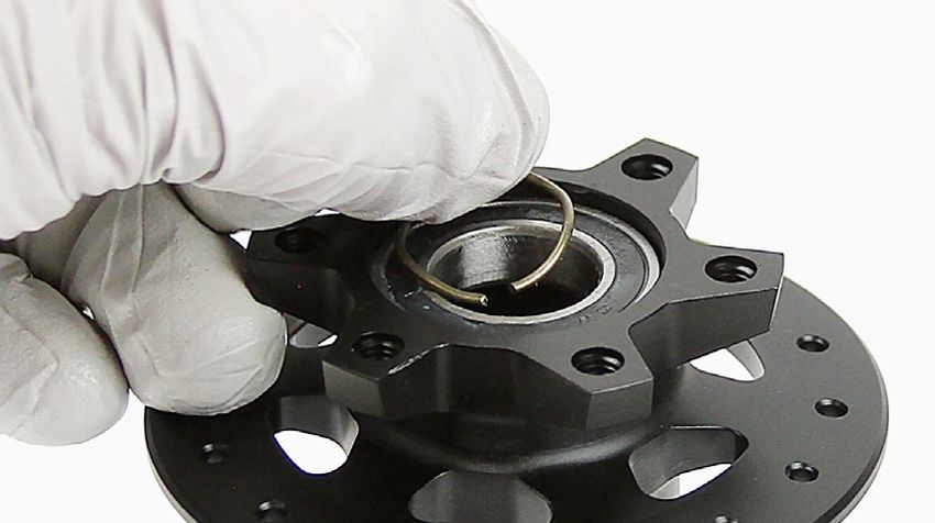
SRAM® LLC WARRANTY
THIS WARRANTY GIVES YOU SPECIFIC LEGAL RIGHTS AGAINST SRAM, LLC. YOU MAY ALSO HAVE OTHER RIGHTS THAT VARY FROM
STATE TO STATE, COUNTRY, OR PROVINCE. THIS WARRANTY DOES NOT AFFECT YOUR STATUTORY RIGHTS. TO THE EXTENT THIS
WARRANTY IS INCONSISTENT WITH THE LOCAL LAW, THIS WARRANTY SHALL BE DEEMED MODIFIED TO BE CONSISTENT WITH SUCH
LAW. FOR A FULL UNDERSTANDING OF YOUR RIGHTS, CONSULT THE LAWS OF YOUR COUNTRY, PROVINCE, OR STATE.
THIS WARRANTY APPLIES TO SRAM PRODUCTS MADE UNDER THE SRAM®, ROCKSHOX®, TRUVATIV®, ZIPP®, QUARQ®, AVID® AND TIME®
BRAND NAMES.
EXTENT OF LIMITED WARRANTY
Except as otherwise set forth herein, SRAM warrants its bicycle components to be free from defects in materials or workmanship for a period of two
(2) years after original purchase of the product.
SRAM warrants all Zipp MOTO Wheels and Rims to be free from defects in materials or workmanship for the lifetime of the product.
SRAM warrants all non-electronic Zipp branded bicycle components, Model Year 2021 or newer, to be free from defects in materials or workmanship
for the lifetime of the product.
GENERAL PROVISIONS
This warranty only applies to the original owner and is not transferable. Claims under this warranty must be made through the retailer where the
bicycle or the SRAM product was purchased or a SRAM authorized service location. Original proof of purchase is required. All SRAM warranty claims
will be evaluated by a SRAM authorized service location whereupon acceptance of the claim the product will be repaired, replaced, or refunded at
SRAM's discretion. To the extent allowed by local law claims under this warranty must be made during the warranty period and within one (1) year
following the date on which any such claim arises.
NO OTHER WARRANTIES
EXCEPT AS DESCRIBED HEREIN, AND TO THE EXTENT ALLOWED BY LOCAL LAW, SRAM MAKES NO OTHER WARRANTIES, GUARANTIES, OR
REPRESENTATIONS OF ANY TYPE (EXPRESS OR IMPLIED), AND ALL WARRANTIES (INCLUDING ANY IMPLIED WARRANTIES OF REASONABLE
CARE, MERCHANTABILITY, OR FITNESS FOR A PARTICULAR PURPOSE) ARE HEREBY DISCLAIMED.
LIMITATIONS OF LIABILITY
EXCEPT AS DESCRIBED HEREIN, AND TO THE EXTENT PERMITTED BY LAW, IN NO EVENT SHALL SRAM OR ITS THIRD PARTY SUPPLIERS BE
LIABLE FOR DIRECT, INDIRECT, SPECIAL, INCIDENTAL, OR CONSEQUENTIAL DAMAGES. SOME STATES (COUNTRIES AND PROVINCES) DO NOT
ALLOW THE EXCLUSION OR LIMITATION OF INCIDENTAL DAMAGES, SO THE ABOVE LIMITATION MAY NOT APPLY TO YOU.
LIMITATIONS OF WARRANTY
This warranty does not apply to products that have been incorrectly installed, adjusted, and/or maintained according to the respective SRAM user
manual. The SRAM user manuals can be found online at sram.com/service.
This warranty does not apply to damage to the product caused by a crash, impact, abuse of the product, non-compliance with manufacturer's
specifications of intended usage, or any other circumstances in which the product has been subjected to forces or loads beyond its design.
This warranty does not apply when the product has been modified, including but not limited to, any attempt to open or repair any electronic and
electronic related components, including the motor, controller, battery packs, wiring harnesses, switches, and chargers.
This warranty does not apply when the serial number or production code has been deliberately altered, defaced, or removed.
SRAM components are designed for use only on bicycles that are pedal powered or pedal assisted (e-Bike/Pedelec).
Notwithstanding anything else set forth herein, the battery pack and charger warranty does not include damage from power surges, use of improper
charger, improper maintenance, or such other misuse.
This warranty shall not cover damages caused by the use of parts of different manufacturers or parts that are not compatible or suitable for use with
SRAM components.
This warranty shall not cover damages resulting from commercial (rental) use.
WEAR AND TEAR
This warranty does not apply to normal wear and tear. Wear and tear parts are subject to damage as a result of normal use, failure to service
according to SRAM recommendations, and/or riding or installation in conditions or applications other than recommended.
WEAR AND TEAR PARTS INCLUDE:
• Aero bar pads            • Chains                                        • Jockey wheels                       • Sprockets
• Air sealing o-rings      • Cleats                                        • Rear shock mounting                 • Stripped threads/bolts (aluminum,
• Batteries                • Corrosion                                       hardware and main seals               titanium, magnesium or steel)
• Bearings                 • Disc brake rotors                             • Rubber moving parts                 • Tires
• Bottomout pads           • Dust seals                                    • Shifter and Brake cables            • Tools
• Brake pads               • Free hubs, Driver bodies, Pawls                 (inner and outer)                   • Transmission gears
• Bushings                 • Foam rings, Glide rings                       • Shifter grips                       • Upper tubes (stanchions)
• Cassettes                • Handlebar grips                               • Spokes                              • Wheel braking surfaces

ZIPP IMPACT REPLACEMENT POLICY
Zipp branded products, Model Year 2021 or newer, are covered under a lifetime impact-damage replacement policy. This policy can be used to obtain
a replacement of a product in the event of non-warranty impact damage occurring while riding your bicycle. See www.zipp.com/support for more
information.

TABLE OF CONTENTS
ZIPP SERVICE........................................................................................................................................................................................................5
       PART PREPARATION........................................................................................................................................................................................................................................5
       SERVICE PROCEDURES..................................................................................................................................................................................................................................5

RIM AND WHEEL BUILDING SPECIFICATIONS...............................................................................................................................................5

REAR HUB SERVICE.............................................................................................................................................................................................6
       COMPONENT REMOVAL................................................................................................................................................................................................................................6
       PARTS, TOOLS, AND SUPPLIES...................................................................................................................................................................................................................6
       EXPLODED VIEW - REAR HUB...................................................................................................................................................................................................................... 7
       REAR HUB END CAPS.....................................................................................................................................................................................................................................7
       REAR HUB BEARING REMOVAL...................................................................................................................................................................................................................8
       REAR HUB BEARING INSTALLATION....................................................................................................................................................................................................... 12
       DRIVER CLEANING (OPTIONAL) - COIL SPRING DRIVER.................................................................................................................................................................. 16
       DRIVER CLEANING (OPTIONAL) - LEAF SPRING DRIVER................................................................................................................................................................. 19
       DRIVER BEARING REPLACEMENT (OPTIONAL)................................................................................................................................................................................... 21

FRONT HUB SERVICE....................................................................................................................................................................................... 23
       COMPONENT REMOVAL............................................................................................................................................................................................................................. 23
       PARTS, TOOLS, AND SUPPLIES................................................................................................................................................................................................................ 23
       EXPLODED VIEW - FRONT HUB................................................................................................................................................................................................................ 24
       FRONT HUB END CAPS............................................................................................................................................................................................................................... 24
       FRONT HUB BEARING REMOVAL............................................................................................................................................................................................................ 25
       FRONT HUB BEARING INSTALLATION................................................................................................................................................................................................... 28

                                                                                                                                                                                                                     Table of Contents                       3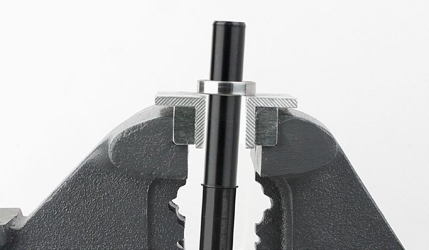
SAFETY FIRST!
We care about YOU. Please, always wear your safety glasses
  and protective gloves when servicing SRAM® products.
          Protect yourself! Wear your safety gear!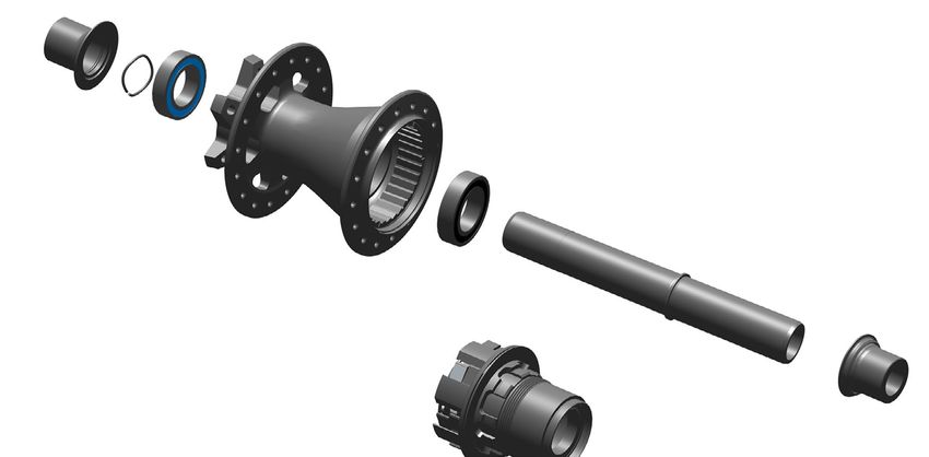
Zipp Service
We recommend that you have your Zipp compononets serviced by a qualified bicycle mechanic. Servicing Zipp compononets requires the use of
specialized tools. Failure to follow the procedures outlined in this service manual may cause damage to your component and void the warranty.
Visit www.zipp.com/support for the latest Zipp Spare Parts catalog and technical information. For order information, please contact your local Zipp
distributor or dealer.
Information contained in this publication is subject to change at any time without prior notice.
Your product's appearance may differ from the pictures contained in this publication.
      For recycling and environmental compliance information, please visit www.sram.com/company/environment.

 Part Preparation
Remove the component from the bicycle before service.
Clean the exterior of the product with mild soap and water to avoid contamination of internal sealing part surfaces.

 Service Procedures
The following procedures should be performed throughout service, unless otherwise specified.

Clean the part with isopropyl alcohol and a clean, lint-free shop towel.
Clean the sealing surface on the part and inspect it for scratches.

 Rim and Wheel Building Specifications
For spoke lengths, tension, rim ERD, hub dimensions, and technical specifications, please refer the the Zipp Wheel Specifications document
available at sram.com/service.

                                                                                                                                   Zipp Service       5
Rear Hub Service

 Component Removal
Prior to service, remove the wheels from the bicycle according to the bicycle manufacturer's instructions and thoroughly clean the exterior of the
product to avoid contamination of internal sealing part surfaces.
For additional information about Zipp wheels and hubs, user manuals are available at www.Zipp.com.

 P a r t s , To o l s , a n d S u p p l i e s
Parts                                                                       Bicycle Tools
• WHEEL BEARING KIT FRONT/REAR FOR ZIPP ZR1/ZM2 HUBS, 61903                 • Axle and Spindle Vise Inserts - Park Tool AV-4 or AV-5
• WHEEL FREEHUB KIT - ZIPP ZM2 XD (optional)                                • Blind Hole Bearing Puller Set
• WHEEL FREEHUB KIT - ZIPP ZM2 10 SPD (optional)                               • 17 mm slotted attachment
Safety and Protection Supplies                                              • Wheels Manufacturing Press-1 Sealed Bearing Press Kit or similar
• Apron                                                                        • 6903 30x17 bearing press adapters (x2)
• Clean, lint-free shop towels                                                 • 6803 26x17 bearing press adapters (x2) (optional)
• Nitrile gloves                                                               • T-handle threaded bearing press
• Safety glasses                                                            Common Tools
Lubricants and Fluids                                                       • Bench vise
• Isopropyl alcohol                                                         • Flat blade screwdriver
• Zipp Cognition or Klüber Staburags NBU30 grease                           • Needle-nose pliers
• SRAM Butter grease                                                        • Grease brush
Zipp/SRAM Tools                                                             • Rubber or plastic mallet
• Zipp 61903 Bearing Press Tool (x2)                                        • Vise soft jaws (aluminum)
  or
  Zipp 61903 Bearing Press Tool (x1) and
  SRAM 6903 Bearing Press Tool (x1)

                                                         SAFETY INSTRUCTIONS
 Always wear nitrile gloves when working with bicycle grease.

                                                                                                                               Rear Hub Service      6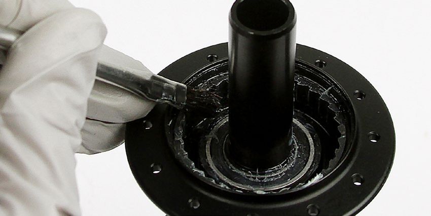
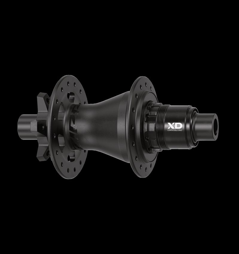
Exploded View - Rear Hub

                           Zipp 6903/61903 hub bearing
                                                           Hub Shell

                                                                                         Zipp 6903/61903 hub bearing

End Cap
    Wave Spring

                                                                                                                    Axle

                                                    Ratchet Ring

                                                                                                                                                         End Cap

             Driver Body                              Driver Body
              SRAM XD                               SRAM 10/11 Speed

 Rear Hub End Caps

                                                                              DRIVE SIDE                                              NON DRIVE SIDE

                                                           Current             Previous                                 Current           Previous
                                                                                                  Spare Part Kit                                            Spare Part Kit
    Hub                     Variants                    Identification       Identification                          Identification     Identification
                                                                                                    Number                                                    Number
                                                      Text On End Cap      Text On End Cap                         Text On End Cap    Text On End Cap

                                            10SPD
    ZM2     REAR     12 X 148          6B                 151-030        12x(142/148) DS XD(R)   11.2018.064.007       212-000               —             11.2018.064.007
                                             XD

                                                                                                                                      Exploded View - Rear Hub               7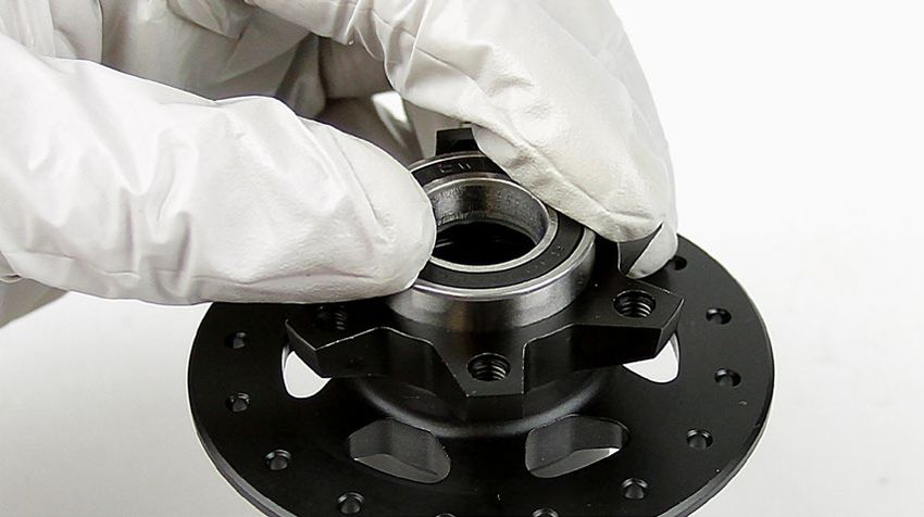
Rear Hub Bearing Removal
Procedures are the same for rim brake and disc brake rear hubs. Disc brake hub pictured.

 1    Insert the Park Tool AV-4 or AV-5 Axle and Spindle Vise Insert tool into
      a vise. Clamp one end cap into the vise insert tool and pull up on the
      wheel/hub to remove the end cap.
      Repeat to remove the other end cap.

                                                                                  AV-4 / AV-5         AV-4 / AV-5

 2    Pull the driver body from the hub by hand.

 3    Inspect the rubber seal for damage. If the seal is damaged, replace the
      driver body.

 4    Use a plastic mallet to tap the non-drive side end of the axle to remove
      the axle and bearing from the hub.
      Pull the axle and drive side bearing out of the drive side of the hub.
      If the drive side bearing was not removed with the axle, it must be
      removed with the Bearing Puller tool as instructed in step 7.

                                                                                  Plastic Mallet

                                                                                                   Rear Hub Bearing Removal   8
5   The wave spring installed on the non-drive side of the axle will slide off
    when the axle is removed. Set the wave spring aside.

                                   NOTICE
     Do not discard or misplace the wave spring. It is crucial to hub
     performance and the hub will not fuction properly without the spring.

6   Note: If the drive side bearing is not removed with the axle, a bearing
    puller must be used to remove the bearing from the hub.
    Place the axle in between flat aluminum vise soft jaws, drive side
    down, with the bearing resting on top of the soft jaws. Make sure the
    axle bearing step does not contact the soft jaws. Use a plastic mallet
    to gently tap on the top of the non-drive end of the axle until it is
    dislodged from the bearing. Discard the bearing.

                                   NOTICE
     To avoid damage to the axle, do not allow the axle to contact the
     vise soft jaws. If the axle bearing step is damaged, the axle must be
     replaced.
                                                                                                        Plastic Mallet

7   Clean the axle with isopropyl alcohol and a shop towel.

                                   NOTICE
     To prevent damage to the hub surfaces, do not use acetone or similar
     products to clean parts.

                                                                                 Isopropyl Alcohol                       Shop Towel

                                                                                                     Rear Hub Bearing Removal         9
8   Insert the 17 mm Bearing Puller slotted attachment through the drive
    side bearing. Align the slotted attachment with the bottom of the
    bearing, and expand it inside the bearing.
    Do not over tighten the slotted attachment. For more detailed assembly
    and usage, see the bearing puller manufacturer's instructions.
    Grip the slide hammer and forcefully pull away from the slotted
    attachment to remove the bearing from the driver body.

                                                                              17 mm Slotted Attachment

9   Insert the 17 mm Bearing Puller slotted attachment through the non-
    drive side bearing. Align the slotted attachment with the bottom of the
    bearing, and expand it inside the bearing.
    Do not over tighten the slotted attachment. For more detailed assembly
    and usage, see the bearing puller manufacturer's instructions.
    Grip the slide hammer and forcefully pull away from the slotted
    attachment to remove the bearing from the driver body.

                                                                              17 mm Slotted Attachment

                                                                                                         Rear Hub Bearing Removal   10
10 Clean the bearing bores with isopropyl alcohol and a shop towel.
Isopropyl Alcohol Shop Towel
11 Clean the ratchet ring and hub internals with isopropyl alcohol, a shop
towel, and cotton swabs. Do not remove the ratchet ring.
Rear Hub Bearing Removal 11Rear Hub Bearing Installation
NOTICE
To prevent damage when pressing the bearings into the rear hub, make sure that the bearing press tool contacts both the inner and outer races of
the bearing.
1 Install a new Zipp 6903/61903 hub bearing into the non-drive side of
the hub with the black seal facing outward.
Note: Ceramic bearings have blue seals on both sides of the bearing;
installation orientation is not important.
2 Install a 6903 30x17 tool into the drive-side bearing bore.
Insert the threaded rod through the drive side of the hub shell. Slide a
second 6903 30x17 tool onto the threaded rod.
Thread the Press Tool handle onto the threaded rod.
Turn the handle clockwise to press the bearing into the hub until it is
hand-tight.
Do not overtighten the bearing.
Remove the tools.
NOTICE
To prevent damage when pressing the bearing into the hub, make
6903 30x17 6903 30x17
sure that the bearing press tools contact both the inner and outer
bearing races or bearing bores and not the hub shell.
3 Install a new bearing onto the longer, non-drive side of the axle, with
the blue bearing seal facing away from the raised step on the axle.
Note: Ceramic bearings have blue seals on both sides of the bearing;
installation orientation is not important.
Insert the non-drive side of the axle into a Zipp 61903 tool, with the flat,
non-stepped end of the tool against the bearing.
Zipp 61903
Rear Hub Bearing Installation 124 Use a rubber or plastic mallet to tap the drive side of the axle until the
raised step on the axle contacts the bearing
Remove the axle from the tool.
Plastic Mallet
5 Insert a SRAM 6903 tool into the non-drive side bearing bore with the
flat, non-stepped end of the tool against the bearing.
Install the non-drive side end of the axle through the hub and into the
SRAM 6903 tool.
SRAM 6903
6 Install a Zipp 61903 tool onto the drive side end of the axle with the
stepped end of the tool contacting the bearing.
Zipp 61903 Stepped End
7 Use a rubber mallet to tap the drive side of the axle until the raised
step on the axle contacts the bearing
Remove the tool from the axle.
Plastic Mallet
Rear Hub Bearing Installation 138 Apply grease to the ratchet ring (a) and the seal surface (b) of the hub
shell.
NOTICE
If a brush is used to apply grease, confirm there are no loose bristles
in the grease or on the part.
SRAM Butter Grease
9 Apply grease to the last 10-15mm of the axle. Installation of the driver
body will distribute the grease on the entire hub axle.
NOTICE
If a brush is used to apply grease, confirm there are no loose bristles
in the grease or on the part.
Cognition / Klüber Staburags NBU30 grease
10 Install the driver body onto the axle and twist it counter-clockwise to
seat the driver body and driver body seal.
Make sure the driver body seal is fully seated into the seal groove.
The installation process is the same for 10 speed and XD driver bodies.
11 Install the wave spring onto the non-drive side of the axle. You may
need a tool to press the wave spring against the bearing face.
NOTICE
Do not scratch the axle when using a tool to install the wave spring.
The wave spring is crucial to hub performance and must be installed
onto the axle.
Rear Hub Bearing Installation 1412 Apply grease to the following locations on the drive side and non-drive
side axle end:
• Axle front surface (a)
• Axle radial surface (b) a a
• Bearing front face across bearing seal, inner- and outer ring (c)
b b
NOTICE
If a brush is used to apply grease, confirm there are no loose bristles
c c
in the grease or on the part.
Cognition / Klüber Staburags NBU30 grease
13 Press the end caps onto the axle.
14 Clean the hub with isopropyl alcohol and a shop towel.
Shop towel Isopropyl alcohol
Rear Hub Bearing Installation 15Reinigung des Freilaufs (optional) – Freilauf mit Schraubenfedern
HINWEIS
Die Wartung eines 11-Gang-Freilaufs ist identisch mit der nachfolgend gezeigten Wartung eines XDR-Freilaufs.
1 Prüfen Sie die Gummidichtung auf Beschädigungen. Wenn die
Dichtung beschädigt ist, tauschen Sie den Freilauf aus.
2 Heben Sie mit den Fingern oder einem kleinen Schlitzschraubendreher
den Sprengring aus dem Freilauf.
3 Entfernen Sie mit den Fingern, einem Dorn oder einer Spitzzange die
Sperrklinken und Schraubenfedern aus dem Freilauf.
4 Säubern Sie die Sperrklinken-Nuten mit einem Wattestäbchen und den
Freilaufkörper mit Isopropyl-Alkohol und einem Werkstatttuch.
Reinigung des Freilaufs (optional) – Freilauf mit Schraubenfedern 165 Tragen Sie mit einer Fettspritze ein wenig SRAM Butter-Schmierfett auf
die Sperrklinkennuten auf.
SRAM Butter-Schmierfett
6 Setzen Sie eine Schraubenfeder in eine der unteren Federnuten
ein und montieren Sie dann eine schwarze Sperrklinke in der
Sperrklinkennut.
Hinweis: Die Federn und Sperrklinken sind symmetrisch und können in
einer beliebigen Ausrichtung montiert werden.
7 Drücken Sie die Feder mit einem kleinen Schlitzschraubendreher
zusammen, damit die Sperrklinke in die Nut fallen kann, und
justieren Sie dann die Feder so, dass sie senkrecht zur Rückseite der
Sperrklinke steht.
Schlitzschraubendreher
8 Setzen Sie eine Schraubenfeder in die obere Federnut über der
zuvor installierten Sperrklinke/Feder ein und montieren Sie dann eine
silberne Sperrklinke in der Sperrklinkennut.
Hinweis: Die Federn und Sperrklinken sind symmetrisch und können in
einer beliebigen Ausrichtung montiert werden.
Reinigung des Freilaufs (optional) – Freilauf mit Schraubenfedern 179 Drücken Sie die Feder mit einem kleinen Schlitzschraubendreher
zusammen, damit die Sperrklinke in die Nut fallen kann, und
justieren Sie dann die Feder so, dass sie senkrecht zur Rückseite der
Sperrklinke steht.
Wiederholen Sie die Schritte 6 bis 9, um die anderen Federn und
Sperrklinken einzubauen.
Stellen Sie sicher, dass die schwarzen Sperrklinken in der unteren
Nutenreihe installiert werden.
Schlitzschraubendreher
10 Richten Sie das Ende des Sprengrings auf die Bohrung im Freilauf
aus und drücken Sie den Sprengring in den Kanal des Freilaufs, bis er
ordnungsgemäß sitzt.
Reinigung des Freilaufs (optional) – Freilauf mit Schraubenfedern 18Reinigung des Freilaufs (optional) – Freilauf mit Schraubenfedern
HINWEIS
Die Wartung eines 11-Gang-Freilaufs ist identisch mit der nachfolgend gezeigten Wartung eines XDR-Freilaufs.
1 Prüfen Sie die Gummidichtung auf Beschädigungen. Wenn die
Dichtung beschädigt ist, tauschen Sie den Freilauf aus.
2 Heben Sie mit den Fingern oder einem kleinen Schlitzschraubendreher
den Sprengring aus dem Freilauf.
3 Entfernen Sie mit den Fingern, einem Dorn oder einer Spitzzange die
Sperrklinken und Schraubenfedern aus dem Freilauf.
4 Säubern Sie die Sperrklinken-Nuten mit einem Wattestäbchen und den
Freilaufkörper mit Isopropyl-Alkohol und einem Werkstatttuch.
Reinigung des Freilaufs (optional) – Freilauf mit Schraubenfedern 195 Tragen Sie mit einer Fettspritze ein wenig SRAM Butter-Schmierfett auf
die Sperrklinkennuten auf.
SRAM Butter-Schmierfett
6 Setzen Sie eine Schraubenfeder in eine der unteren Federnuten
ein und montieren Sie dann eine schwarze Sperrklinke in der
Sperrklinkennut.
Hinweis: Die Federn und Sperrklinken sind symmetrisch und können in
einer beliebigen Ausrichtung montiert werden.
7 Drücken Sie die Feder mit einem kleinen Schlitzschraubendreher
zusammen, damit die Sperrklinke in die Nut fallen kann, und
justieren Sie dann die Feder so, dass sie senkrecht zur Rückseite der
Sperrklinke steht.
Schlitzschraubendreher
8 Setzen Sie eine Schraubenfeder in die obere Federnut über der
zuvor installierten Sperrklinke/Feder ein und montieren Sie dann eine
silberne Sperrklinke in der Sperrklinkennut.
Hinweis: Die Federn und Sperrklinken sind symmetrisch und können in
einer beliebigen Ausrichtung montiert werden.
Reinigung des Freilaufs (optional) – Freilauf mit Schraubenfedern 209 Drücken Sie die Feder mit einem kleinen Schlitzschraubendreher
zusammen, damit die Sperrklinke in die Nut fallen kann, und
justieren Sie dann die Feder so, dass sie senkrecht zur Rückseite der
Sperrklinke steht.
Wiederholen Sie die Schritte 6 bis 9, um die anderen Federn und
Sperrklinken einzubauen.
Stellen Sie sicher, dass die schwarzen Sperrklinken in der unteren
Nutenreihe installiert werden.
Schlitzschraubendreher
10 Richten Sie das Ende des Sprengrings auf die Bohrung im Freilauf
aus und drücken Sie den Sprengring in den Kanal des Freilaufs, bis er
ordnungsgemäß sitzt.
Reinigung des Freilaufs (optional) – Freilauf mit Schraubenfedern 21Reinigung des Freilaufs (optional) – Freilauf mit Schraubenfedern
HINWEIS
Die Wartung eines 11-Gang-Freilaufs ist identisch mit der nachfolgend gezeigten Wartung eines XDR-Freilaufs.
1 Prüfen Sie die Gummidichtung auf Beschädigungen. Wenn die
Dichtung beschädigt ist, tauschen Sie den Freilauf aus.
2 Heben Sie mit den Fingern oder einem kleinen Schlitzschraubendreher
den Sprengring aus dem Freilauf.
3 Entfernen Sie mit den Fingern, einem Dorn oder einer Spitzzange die
Sperrklinken und Schraubenfedern aus dem Freilauf.
4 Säubern Sie die Sperrklinken-Nuten mit einem Wattestäbchen und den
Freilaufkörper mit Isopropyl-Alkohol und einem Werkstatttuch.
Reinigung des Freilaufs (optional) – Freilauf mit Schraubenfedern 225 Tragen Sie mit einer Fettspritze ein wenig SRAM Butter-Schmierfett auf
die Sperrklinkennuten auf.
SRAM Butter-Schmierfett
6 Setzen Sie eine Schraubenfeder in eine der unteren Federnuten
ein und montieren Sie dann eine schwarze Sperrklinke in der
Sperrklinkennut.
Hinweis: Die Federn und Sperrklinken sind symmetrisch und können in
einer beliebigen Ausrichtung montiert werden.
7 Drücken Sie die Feder mit einem kleinen Schlitzschraubendreher
zusammen, damit die Sperrklinke in die Nut fallen kann, und
justieren Sie dann die Feder so, dass sie senkrecht zur Rückseite der
Sperrklinke steht.
Schlitzschraubendreher
8 Setzen Sie eine Schraubenfeder in die obere Federnut über der
zuvor installierten Sperrklinke/Feder ein und montieren Sie dann eine
silberne Sperrklinke in der Sperrklinkennut.
Hinweis: Die Federn und Sperrklinken sind symmetrisch und können in
einer beliebigen Ausrichtung montiert werden.
Reinigung des Freilaufs (optional) – Freilauf mit Schraubenfedern 239 Drücken Sie die Feder mit einem kleinen Schlitzschraubendreher
zusammen, damit die Sperrklinke in die Nut fallen kann, und
justieren Sie dann die Feder so, dass sie senkrecht zur Rückseite der
Sperrklinke steht.
Wiederholen Sie die Schritte 6 bis 9, um die anderen Federn und
Sperrklinken einzubauen.
Stellen Sie sicher, dass die schwarzen Sperrklinken in der unteren
Nutenreihe installiert werden.
Schlitzschraubendreher
10 Richten Sie das Ende des Sprengrings auf die Bohrung im Freilauf
aus und drücken Sie den Sprengring in den Kanal des Freilaufs, bis er
ordnungsgemäß sitzt.
Reinigung des Freilaufs (optional) – Freilauf mit Schraubenfedern 24Driver Cleaning (optional) - Coil Spring Driver
NOTICE
Service of an 11 speed driver is identical to the XDR driver service shown below.
1 Inspect the rubber seal for damage. If the seal is damaged, replace the
driver.
2 Use your fingers or a small flat blade screwdriver to lift the snap ring
from the driver.
3 Use your fingers, a pick, or needle-nose pliers to remove the pawls and
coil springs from the driver.
4 Clean the pawl slots with a cotton swab and the driver body with
isopropyl alcohol and a shop towel.
Driver Cleaning (optional) - Coil Spring Driver 255 Using a grease syringe, apply a small amount of SRAM Butter grease to
the pawl slots.
SRAM Butter Grease
6 Insert a coil spring into one of the lower spring slots, then install a
black pawl into the pawl slot.
Note: The springs and pawls are symmetrical and can be installed in
any orientation.
7 Use a small flat blade screwdriver to compress the spring to allow
the pawl to drop into the slot, then adjust the spring so that it is
perpendicular to the back of the pawl.
Flat blade screwdriver
8 Insert a coil spring into the upper spring slot above the previously
installed pawl/spring, then install a silver pawl into the pawl slot.
Note: The springs and pawls are symmetrical and can be installed in
any orientation.
Driver Cleaning (optional) - Coil Spring Driver 269 Use a small flat blade screwdriver to compress the spring to allow
the pawl to drop into the slot, then adjust the spring so that it is
perpendicular to the back of the pawl.
Repeat steps 6-9 to install the other springs and pawls.
Make sure the black pawls are installed in the lower row of slots.
Flat blade screwdriver
10 Orient the end of the snap ring into the hole in the driver and push the
snap ring onto the channel of the driver until it is fully seated.
Driver Cleaning (optional) - Coil Spring Driver 27Driver Cleaning (optional) - Leaf Spring Driver
NOTICE
Service of an 11 speed driver is identical to the XDR driver service shown below.
1 Inspect the rubber seal for damage. If the seal is damaged, replace the
driver.
2 Use a small flat blade screwdriver to lift the snap ring from the driver.
Flat Head Screwdriver
3 Use a pick or needle-nose pliers to remove the pawls and leaf springs
from the driver.
Needle-nose Pliers Pick
4 Using a grease syringe, apply a small amount of SRAM Butter grease to
the pawl slots.
SRAM Butter Grease
Driver Cleaning (optional) - Leaf Spring Driver 285 Insert the leaf springs into the spring slots. Orient the long edge of
each spring along the inside of the carrier so that it points clockwise.
NOTICE
Do not force the spring into the slot; it should slide in easily. Forcing
the spring into the slot can bend or damage the spring requiring
replacement of the driver.
6 Insert the black pawls into the pawl slots followed by the silver pawls.
Use a pick or flat blade screwdriver to compress each leaf spring to
assist with inserting the pawls.
Pick
7 Orient the end of the snap ring into the hole in the driver and push the
snap ring onto the channel of the driver until it is fully seated.
Driver Cleaning (optional) - Leaf Spring Driver 29Driver Bearing Replacement (optional)
NOTICE
Service of a 10 speed driver is identical to the XD driver service shown below.
1 Insert the 17 mm Bearing Puller slotted attachment through the
outboard bearing. Align the slotted attachment with the bottom of the
bearing, and expand it inside the bearing.
Do not over tighten the slotted attachment. For more detailed assembly
and usage, see the bearing puller manufacturer’s instructions.
Thread the rod of the bearing puller into the attachment. Grip the slide
hammer and forcefully pull away from the slotted attachment to remove
the bearing from the driver body.
17 mm Slotted Attachment
2 Insert the 17 mm Bearing Puller slotted attachment through the inboard
bearing. Align the slotted attachment with the bottom of the bearing
and expand it inside the bearing.
Do not over tighten the slotted attachment. For more detailed assembly
and usage, see the bearing puller manufacturer’s instructions.
Thread the rod of the bearing puller into the attachment. Grip the slide
hammer and forcefully pull away from the slotted attachment to remove
the bearing from the driver body.
17 mm Slotted Attachment
3 Clean the driver bearing bores with a shop towel and cotton swabs.
4 Place the driver on flat surface, outboard side up. Insert a new Zipp
6803/61803 driver bearing into the outboard side of the driver body,
with the black seal facing outward.
Note: Ceramic bearings have blue seals on both sides of the bearing;
installation orientation is not important.
Insert a 6803 26x17 tool onto the bearing.
6803/61803 Driver Bearing 6803 26x17
Driver Bearing Replacement (optional) 305 Insert the threaded rod through the bearing on the outboard side of
the driver. Slide a second 6803 26x17 tool onto the threaded rod.
Thread the Press Tool handle onto the threaded rod.
Turn the handle clockwise to press the bearing into the driver body
until it is hand-tight.
Do not overtighten the bearing.
Remove the tools.
NOTICE
To prevent damage when pressing the bearing into the driver body,
make sure that the bearing press tools contact both the inner and
outer bearing races or bearing bores and not the driver body. 6803 26x17
6 Place the driver on a flat surface, inboard side up. Insert a new Zipp
6803/61803 driver bearing into the inboard side of the driver body,
with the black seal facing outward.
Note: Ceramic bearings have blue seals on both sides of the bearing;
installation orientation is not important.
Insert a 6803 26x17 tool onto the bearing.
6803/61803 Driver Bearing 6803 26x17
7 Insert the threaded rod through the bearing on the inboard side of the
driver. Slide a second 6803 26x17 tool onto the threaded rod.
Thread the Press Tool handle onto the threaded rod.
Turn the handle clockwise to press the bearing into the driver body
until it is hand-tight.
Do not overtighten the bearing.
Remove the tools.
NOTICE
To prevent damage when pressing the bearing into the driver body,
make sure that the bearing press tools contact both the inner and
outer bearing races or bearing bores and not the driver body. 6803 26x17
Driver Bearing Replacement (optional) 31Front Hub Service
Component Removal
The hub can be serviced while in the wheel. However, if your spokes or rim are damaged, you can remove the hub from the wheel which will make
servicing your hub easier. To remove the hub, use a spoke wrench to de-tension the spokes, then use a pair of metal snips to cut the spokes, remove
the hub from the wheel, and remove the spoke ends from the hub (not pictured).
For additional information about Zipp wheels and hubs, user manuals are available at www.Zipp.com.
P a r t s , To o l s , a n d S u p p l i e s
Parts Bicycle Tools
• WHEEL BEARING KIT FRONT/REAR FOR ZIPP ZR1/ZM2 HUBS, 61903 • Axle and Spindle Vise Inserts - Park Tool AV-4 or AV-5
• WHEEL AXLE END CAP SET FRONT - 15X110 BOOST - ZM2 HUBS • Blind Hole Bearing Puller Set
• WHEEL AXLE END CAP SET FRONT - 15X110 BOOST - TORQUE CAP • 17 mm slotted attachment
ROCKSHOX FORKS - ZM2 HUBS
• Wheels Manufacturing Press-1 Sealed Bearing Press Kit or similar
Safety and Protection Supplies • 6903 30x17 bearing press adapters (x2)
• Apron • T-handle threaded bearing press
• Clean, lint-free shop towels
Common Tools
• Nitrile gloves
• Bench vise
• Safety glasses
• Flat blade screwdriver
Lubricants and Fluids • Grease brush
• Isopropyl alcohol • Rubber or plastic mallet
• Cognition / Klüber Staburags NBU30 grease
• SRAM Butter grease
SAFETY INSTRUCTIONS
Always wear nitrile gloves when working with bicycle grease.
Front Hub Service 32Exploded View - Front Hub
End Cap
Wave Spring
Zipp 6903/61903 hub bearing
Hub Shell
Zipp 6903/61903 hub bearing
Axle
End Cap
Front Hub End Caps
DRIVE SIDE NON DRIVE SIDE
Current Previous Current Previous
Spare Part Kit Spare Part Kit
Hub Variants Identification Identification Identification Identification
Number Number
Text On End Cap Text On End Cap Text On End Cap Text On End Cap
15 x 110 — 165-010 15x(100&110) DS DISC 11.2018.064.001 165-010 15x(100&110) DS DISC 11.2018.064.001
ZM2 FRONT 6B
15 x 110RS — 189-000 15x(100/110)RS DS 6B 11.2018.064.002 189-000 15x(100/110)RS DS 6B 11.2018.064.002
Exploded View - Front Hub 33Front Hub Bearing Removal
1 Insert the Park Tool AV-4 or AV-5 Axle and Spindle Vise Insert tool into
a vise. Clamp the non-drive side end cap into the vise insert tool and
pull up on the wheel/hub to remove the end cap.
AV-4 / AV-5 36/14
21 Gently tap the exposed axle end with a plastic mallet to dislodge the
axle from the hub bearings.
Use your thumb to push the axle through the hub shell and remove the
wave spring from the non drive side hub shell.
NOTICE
Do not discard or misplace the wave spring. It is crucial to hub
performance and the hub will not fuction properly without the spring.
Remove the front axle from the drive side of the hub.
Plastic Mallet
3 Use your fingers to remove the end cap from the drive side of the axle.
Front Hub Bearing Removal 344 Spray isopropyl alcohol onto the axle and clean it with a shop towel.
NOTICE
To prevent damage to the hub surfaces, do not use acetone or similar
products to clean parts.
Isopropyl Alcohol
5 Insert the 17 mm Bearing Puller slotted attachment through the drive
side bearing. Align the slotted attachment with the bottom of the
bearing, and expand it inside the bearing.
Do not over tighten the slotted attachment. For more detailed assembly
and usage, see the bearing puller manufacturer's instructions.
Grip the slide hammer and forcefully pull away from the slotted
attachment to remove the bearing from the hub shell.
17 mm Slotted Attachment
6 Insert the 17 mm Bearing Puller slotted attachment through the non-
drive side bearing. Align the slotted attachment with the bottom of the
bearing, and expand it inside the bearing.
Do not over tighten the slotted attachment. For more detailed assembly
and usage, see the bearing puller manufacturer's instructions.
Grip the slide hammer and forcefully pull away from the slotted
attachment to remove the bearing from the hub shell.
17 mm Slotted Attachment
Front Hub Bearing Removal 357 Clean the hub shell with isopropyl alcohol and a shop towel.
Isopropyl Alcohol Shop Towel
Front Hub Bearing Removal 36Front Hub Bearing Installation
1 Install a new Zipp 6903/61903 hub bearing into the drive side of the
hub with the black seal facing outward.
Note: Ceramic bearings have blue seals on both sides of the bearing;
installation orientation is not important.
2 Slide a 6903 30x17 tool onto the Press Tool threaded rod.
Insert the threaded rod through the bearing on the drive side of the
hub shell. Slide a second 6903 30x17 tool onto the threaded rod.
Thread the Press Tool handle onto the threaded rod.
Turn the handle clockwise to press the bearing into the hub until it is
hand-tight.
Do not overtighten the bearing.
Remove the tools.
NOTICE
To prevent damage when pressing the bearing into the hub, make 6903 30x17 6903 30x17
sure that the bearing press tools contact both the inner and outer
bearing races or bearing bores and not the hub shell.
3 Install a new Zipp 6903/61903 hub bearing into the non-drive side of
the hub with the black seal facing outward.
Note: Ceramic bearings have blue seals on both sides of the bearing;
installation orientation is not important.
Front Hub Bearing Installation 374 Slide a 6903 30x17 tool onto the Press Tool threaded rod.
Insert the threaded rod through the bearing on the non-drive side of
the hub shell. Slide a second 6903 30x17 tool onto the threaded rod.
Thread the Press Tool handle onto the threaded rod.
Turn the handle clockwise to press the bearing into the hub until it is
hand-tight.
Do not overtighten the bearing.
Remove the tools.
6903 30x17 6903 30x17
5 Apply grease to the non-drive side axle bearing race.
Klüber Staburags NBU30 Grease
6 Insert the non-drive side end of the axle into the drive side of the hub,
through the drive side bearing, through the hub, and through the
non-drive side bearing. Press the axle into the hub bearing with your
thumb until the axle bearing step fits flush into the bearing.
Front Hub Bearing Installation 387 Install the wave spring onto the non-drive side of the axle. You may
need a tool to press the wave spring against the bearing face.
NOTICE
Do not scratch the axle when using a tool to install the wave spring.
The wave spring is crucial to hub performance and must be installed
onto the axle.
8 Apply grease to the following locations on the drive side and non-drive
side axle end:
• Axle front surface (a)
• Axle radial surface (b)
• Bearing front face across bearing seal, inner- and outer ring (c)
a
b
c
Klüber Staburags NBU30 grease
9 Press the end caps onto the axle.
10 Clean the hub with isopropyl alcohol and a shop towel.
Isopropyl alcohol Shop towel
Front Hub Bearing Installation 39These are registered trademarks of SRAM, LLC: 1:1®, Accuwatt®, Avid®, ATAC®, AXS®, Bar®, Bioposition®, Blackbox®, BoXXer®, DoubleTap®, eTap®, Firecrest®, Firex®, Grip Shift®, GXP®, Holzfeller®, Hussefelt®, Iclic®, i‑Motion®, Judy®, Know Your Powers®, NSW®, Omnium®, Osmos®, Pike®, PowerCal®, PowerLock®, PowerTap®, Qollector®, Quarq®, RacerMate®, Reba®, Rock Shox®, Ruktion®, Service Course®, ShockWiz®, SID®, Single Digit®, Speed Dial®, Speed Weaponry®, Spinscan®, SRAM®, SRAM APEX®, SRAM EAGLE®, SRAM FORCE®, SRAM RED®, SRAM RIVAL®, Stylo®, TIME®, Truvativ®, TyreWiz®, UDH®, Varicrank®, Velotron®, X0®, X01®, X‑SYNC®, XX1®, Zipp® These are registered logos of SRAM, LLC: These are trademarks of SRAM, LLC: 10K™, 1X™, 202™, 30™, 30 Course™, 35™, 302™, 303™, 353™, 404™, 454™, 808™, 858™, 3ZERO MOTO™ , ABLC™, AeroGlide™, AeroBalance™, AeroLink™, Airea™, Air Guides™, AKA™, AL‑7050‑TV™, Atmos™, Automatic Drive™, AxCad™, Axial Clutch™, Base™, BB5™, BB7™, BB30™, Bleeding Edge™, Blipbox™, BlipClamp™, BlipGrip™, Blips™, Bluto™, Bottomless Tokens™, Cage Lock™, Carbon Bridge™, Centera™, Charger 2™, Charger™, Charger Race Day™, Cleansweep™, Clickbox Technology™, Clics™, Code™, Cognition™, CoLab™, Connectamajig™, Counter Measure™, CYCLO™, DD3™, DD3 Pulse™, DebonAir™, Deluxe™, Deluxe Re:Aktiv™, Descendant™, DFour™, DFour91™, DH™, Dig Valve™, DirectLink™, Direct Route™, Domain™, DOT 5.1™, Double Decker™, Double Time™, Dual Flow Adjust™, Dual Position Air™, DUB™, DUB‑PWR™, DZero™, E300™, E400™, Eagle™, E‑Connect4™, ErgoBlade™, ErgoDynamics™, ESP™, EX1™, Exact Actuation™, Exogram™, Flow Link™, FR‑5™, Full Pin™, G2™, G40™, Giga Pipe™, Gnar Dog™, Guide™, GS™, GX™, Hard Chrome™, Hexfin™, HollowPin™, Howitzer™, HRD™, Hybrid Drive™, Hyperfoil™, i‑3™, Impress™, Jaws™, Jet™, Kage™, Komfy™, LINK™, Lyrik™, MatchMaker™, Maxle™, Maxle 360™, Maxle DH™, Maxle Lite™, Maxle Lite DH™, Maxle Stealth™, Maxle Ultimate™, Micro Gear System™, Mini Block™, Mini Cluster™, Monarch™, Monarch Plus™, Motion Control™, Motion Control DNA™, MRX™, MX™, Noir™, NX™, OCT™, OmniCal™, OneLoc™, Paceline™, Paragon™, PC‑1031™, PC‑1110™, PC‑1170™, PG‑1130™, PG‑1050™, PG‑1170™, Piggyback™, Poploc™, Power Balance™, Power Bulge™, PowerChain™, PowerDomeX™, Powered by SRAM™, PowerGlide™, PowerLink™, Power Pack™, Power Spline™, Predictive Steering™, Pressfit™, Pressfit 30™, Prime™, Qalvin™, R2C™, Rapid Recovery™, Re:Aktiv ThruShaft™, Recon™, Reverb™, Revelation™, Riken™, Roller Bearing Clutch™, Rolling Thunder™, RS‑1™, Rush™, RXS™, Sag Gradients™, Sawtooth™, SCT ‑ Smart Coasterbrake Technology, Seeker™, Sektor™, SHIFT™, ShiftGuide™, Shorty™, Showstopper™, SIDLuxe™, Side Swap™, Signal Gear Technology™, SL™, SL‑70™, SL‑70 Aero™, SL‑70 Ergo™, SL‑80™, Sl‑88™, SLC2™, SL SPEED™, SL Sprint™, Smart Connect™, Solo Air™, Solo Spoke™, Speciale™, SpeedBall™, Speed Metal™, SRAM APEX 1™, SRAM Force 1™, SRAM RIVAL 1™, S‑series™, Stealth‑a‑majig™, StealthRing™, Super‑9™, Supercork™, Super Deluxe™, Super Deluxe Coil™, SwingLink™, SX™, Tangente™, TaperCore™, Timing Port Closure™, TSE Technology™, Tool‑free Reach Adjust™, Top Loading Pads™, Torque Caps™, TRX™, Turnkey™, TwistLoc™, VCLC™, Vivid™, Vivid Air™, Vuka Aero™, Vuka Alumina™, Vuka Bull™, Vuka Clip™, Vuka Fit™, Wide Angle™, WiFLi™, X1™, X3™, X4™, X5™, X7™, X9™, X‑Actuation™, XC™, X‑Dome™, XD™, XDR™, XG‑1150™, XG‑1175™, XG‑1180™, XG‑1190™, X‑Glide™, X‑GlideR™, X‑Horizon™, XLoc Sprint™, XPLR™, XPRESSO™, XPRO™, X‑Range™, XX™, Yari™, ZEB™, Zero Loss™, ZM2™, ZR1™ Specifications and colors subject to change without prior notice. © 2021 SRAM, LLC
ASIAN HEADQUARTERS                WORLD HEADQUARTERS                 EUROPEAN HEADQUARTERS
SRAM Taiwan                       SRAM LLC                           SRAM Europe
No. 1598-8 Chung Shan Road        1000 W. Fulton Market, 4th Floor   Paasbosweg 14-16
Shen Kang Hsiang, Taichung City   Chicago, Illinois 60607            3862ZS Nijkerk
Taiwan R.O.C.                     U.S.A.                             The Netherlands
You can also read