Z-TECH FAN - GO FAN YOURSELF - INSTALLATION AND TECHNICAL OPERATIONS GUIDE
←
→
Page content transcription
If your browser does not render page correctly, please read the page content below
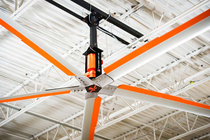
Z-TECH™ FAN

INSTALLATION AND TECHNICAL OPERATIONS GUIDE

  GO FAN YOURSELF, INC. | 1032 NATIONAL PARKWAY | SCHAUMBURG, IL 60173 | www.gofanyourself.com | 1-844-GOFANME (463-2663) OR 1-847-648-4920

                                    GO FAN YOURSELF ®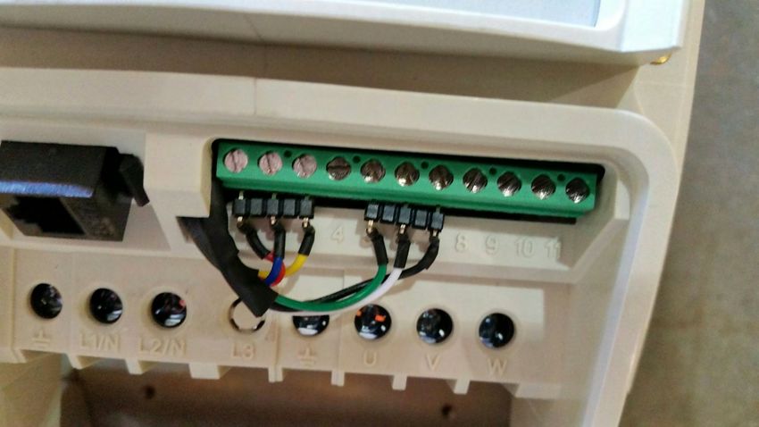
Go Fan Yourself ®
                                                                                                                                                   1032 National Parkway
                                                                                                                                                    Schaumburg, IL 60173
                                                                                                                                              1-844-GOFANME (463-2663)
                                    INSTALLATION CHECK IN / CHECK OUT                                                                                    1-847-648-4920
                                                                                                                                                 www.GoFanYourself.com
                                        Email completed form and required pictures to: drew@gofanyourself.com

        Company:
   Address: City/
        State/Zip:                                                                       Contact Name:
             Email:                                                                                Phone:

                                                    INSTALLATION CHECK IN
 Installation crew supervisor and facility manager are to complete checklist prior to entering the jobsite or unloading materials.
    1. Contractor and customer have reviewed the scope of work/layout including: fan placement, controller placement, and power supply panel(s) to be used.

    2. Contractor and customer have reviewed the fan installation manual for the type of fan mount at each location.

    3. Contractor and customer have reviewed the installation schedule and any site specific safety rules and regulations (i.e., specific requirements, gear, certifications,
       lock out/tag out, prohibited areas, secure areas, areas to avoid, special machinery, dangerous conditions or areas and how to detour such places if needed):

    Additional Comments:

Customer Signature:                                                                      Contractor Signature:
     Printed Name:                                                                              Printed Name:
              Date:                                                                                      Date:

                                                 INSTALLATION CHECK OUT
              Installation crew supervisor and facility manager are to complete checklist after completing installation.
    1. Fan and controller placement agrees with the check in (above), scope of work and layout.

    2. Contractor has reviewed with the customer the breaker location for all fans and the customer understands the lock out/tag out (LOTO) procedure
       on all fan controllers.
    3. No safety incidents were reported by or on the contractor during the fan installation.

    4. All fans are running and the customer has been trained on operation in both directions. The fan operation section of the manual has been reviewed.
    5. The customer understands the warranty for each fan and the warranty information in the manual has been reviewed.
    6. The customer has been given a copy of the installation manual for all styles of GFY ® fans installed as part of this project.
     7. The customer is comfortable with fan operation including starting/stopping, speed adjustment, reversing direction, and power disconnect with LOTO.
    8. The contractor has taken pictures of all fans individually clearing showing the full fan in the ceiling (required to active the warranty).
    9. The contractor has taken pictures of all fans clearly showing the routing and connection of both safety cables (required to active the warranty).
   10. The contractor has taken pictures of all fan controllers once mounted in their final locations (required to activate the warranty).

Customer Signature:                                                                      Contractor Signature:
     Printed Name:                                                                              Printed Name:
              Date:                                                                                      Date:

                                                      GO FAN YOURSELF ®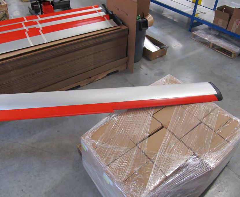
Z-TECH™ FAN                                                                       |2
Installation and Technical Operations

                   Itemized Checklist - Unpacking Your Go Fan Yourself Fan

  Motor Hub Assembly Box
   • There are 3 trays
     inside the Motor
     Hub Assembly Box
        (Trays Detailed On Following Pages)

    • The Blade Stabilizers
      are also inside the
      motor box.

                                                                     Down Tubes 3FT
                                                                     and Longer May
 Blade Box Skid                                                      Also Be
                                                                     Packaged and
                                                                     Shipped On The
                                                                     Blade Box Skid

                                 GO FAN YOURSELF ®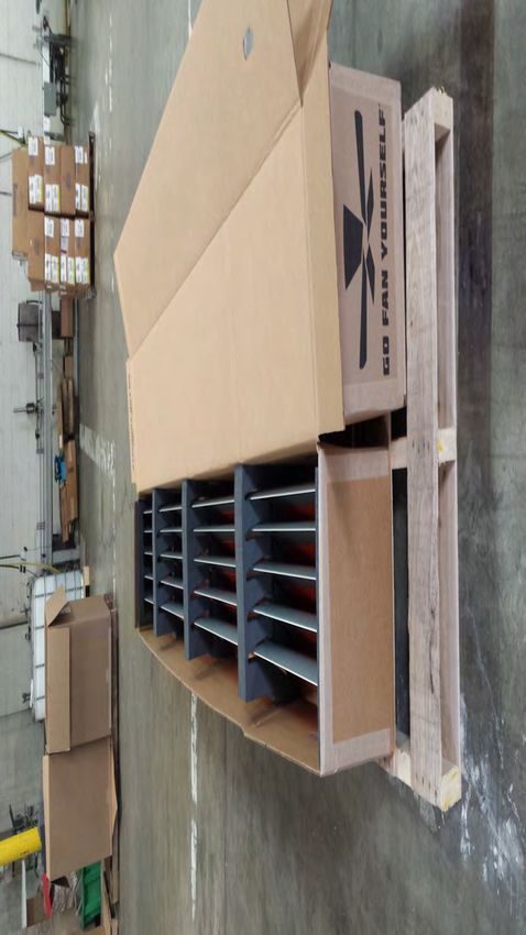
Z-TECH™ FAN                                                                                              |3
Installation and Technical Operations

                  Itemized Checklist - Motor Assembly Box Tray #1 - Top Tray

  Down Tube
  1FT or 2FT Down Tubes Only. Longer
                                                                     Upper Yoke
  Down Tubes will Be Packaged                                        Weldment & Beam
  Separately
                                                                     Clamp Plates

                                                  Accessory Area
            ACS355 or ACS255 VFD                  Typical Items Packed Here Will Include:
            Controller                                 • Z-Purlin Mounting Kit
            ACS255 Controller Shown
                                                       • Wood Beam Mounting Kit
                                                        • Guy Wire Kit
                                                           Your Fan May Include Other Optional Accessories

                               GO FAN YOURSELF ®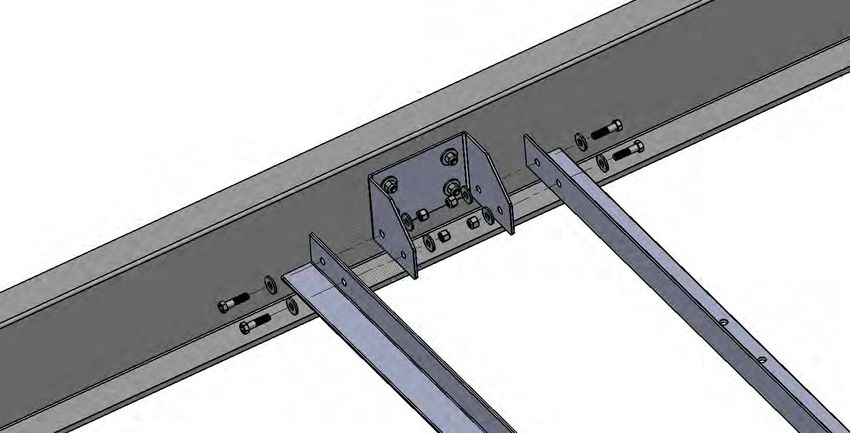
Z-TECH™ FAN                                                                            |4
Installation and Technical Operations

               Itemized Checklist - Motor Assembly Box Tray #2 - Middle Tray

                                          Z-TechSSTM Safety
               Truss Mount Kit          System 3/8" Quick Link   Manual & Optional
            (4) Square Washers                                     Accessories

                                                                           ACS355 or
                                                                           ACS255 VFD
                                                                           Controller
                                                                           (ACS255 Shown)

         Hardware Packs

                             GO FAN YOURSELF ®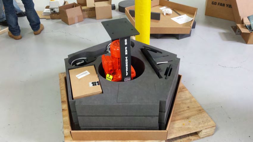
Z-TECH™ FAN                                                                                    |5
Installation and Technical Operations

              Itemized Checklist - Motor Assembly Box Tray #3 - Bottom Tray

                                        Motor Hub Assembly

               Lower Yoke Plates                             Fan Mount Shims
                                                             To Keep The Beam Clamp Plates
                                                             Near Level When Clamping To
                                                             Thicker I-Beams. Add Additional
                                                             Shims If Required.

                             GO FAN YOURSELF ®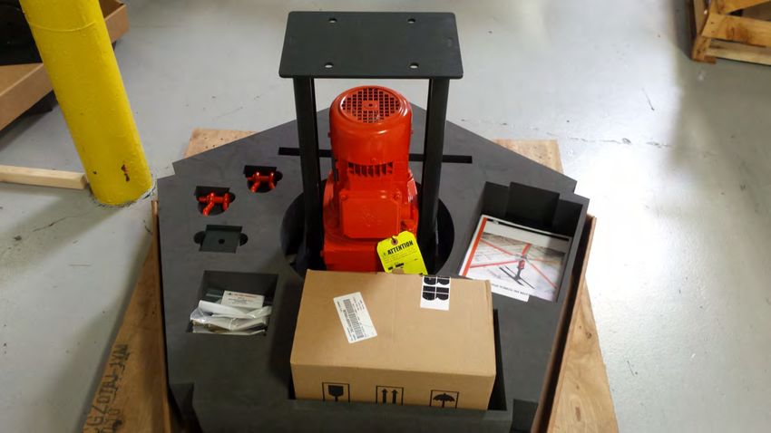
Z-TECH™ FAN                                                                                         |6
Installation and Technical Operations

       Itemized Checklist - ABB VFD Controllers, Blade Box, Blade Stabilizer Box

ABB ACS355 Controller                                         ABB ACS255 Controller
 200-240VAC 3 Phase                                            200-240VAC 1 Phase
 400-480VAC 3 Phase                                            100-120VAC 1 Phase
        Applications                                                  Applications

                                  Itemized Checklist - Fan Blade Box
                      Blade Set (5 Blades) 8ft, 10ft, 12ft, 14ft, 16ft, 18ft, 20ft, 22ft, or 24ft

                             GO FAN YOURSELF ®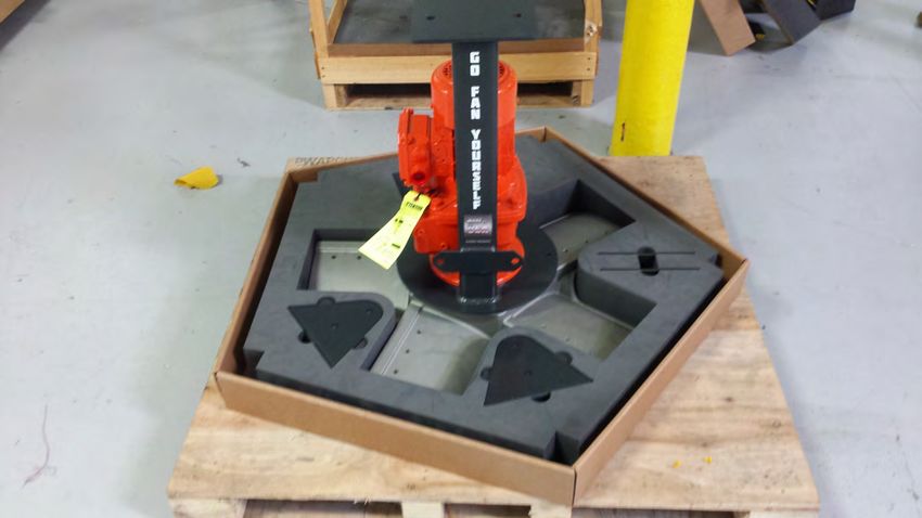
Z-TECH™ FAN                                                                                             |7
Installation and Technical Operations
                                                      Structural
                                                      Support of
                                                      the Building

             Z-TechSSTM Upper
             Safety Straps                                                           Fan Mount
             (wrap as tightly                                                        Assembly
             around building
             structure as possible)                                            (4) 1/2"-13 x 2" Grade 8 Bolts
                                                                               (8) 1/2" Grade 8 Flat Washers
                                                                               (4) 1/2"-13 Grade 8 Nylock Nuts

                  Upper Yoke Weldment
            (one side shown removed so
             Z-TechTM SS Safety System
            connection points are visible)
       (2) 1/2"-13 x 5" Grade 8 Bolts
      (4) 1/2" Grade 8 Flat Washers
    (2) 1/2"-13 Grade 8 Nylock Nuts
                                                                     Down Tube
                                                                     (ordered to length)

                                                                                Fan Mounting Plate
                                                                                (Top of Motor Hub Assembly)
                                                                               (4) 1/2"-13 x 1.5" Grade 8 Bolts
                    Lower Yoke Assembly                                        (8) 1/2" Grade 8 Flat Washers
     (2) 1/2"-13 x 5" Grade 8 Bolts                                            (4) 1/2"-13 Grade 8 Nylock Nuts
    (4) 1/2" Grade 8 Flat Washers
  (2) 1/2"-13 Grade 8 Nylock Nuts

                                                                              GFY ABB Dodge Quantis
                                                                              Z-Tech Drive Motor

                              Fan Frame
                                                                                    Electrical Connection Box

      Z-TechTM SS Lower Safety Straps
      (factory secured to the motor
      mount hardware and field                                                GFY ABB Dodge Quantis
      secured to the down tube)                                               Z-Tech Drive Gearbox
    (1) 3/8"-16 x 5" Grade 8 Bolt
 (2) 3/8" Grade 8 Flat Washers
(1) 3/8"-16 Grade 8 Nylock Nut
                                                                                 Guy Wire Mounting Holes

                                Hub

                                        GO FAN YOURSELF ®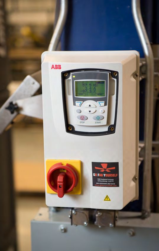
Z-TECH™ FAN                                                                                    |8
Installation and Technical Operations

                                               Table of Contents

      Locate Your GFY®Fan (Recommended Clearances)                                    09
1.    Tools Required to Install Product                                               10
2.    Required Steps Before Installation                                              11
3.    Different Mounting Applications                                                 11
          “I”Beam Mounting Fig.2                                                      11
          Bottom Chord Angle Iron Mount Fig.3                                         11
          Top Chord Angle Iron Mount Fig.4                                            12
          "L - Bracket" Mounting Fig. 5                                               13
          "Z - Purlin" Mounting Fig. 6                                                14
4.    Standard   Mount                                                                15
          What is included in the mount package                                       15
          What standard mounts are available Fig.7                                    15
          How to install the standard mount Fig.8                                     15
5.    Down Tube                                                                       16
          What is included in the down tube package                                   16
          How to install the down tube, upper safety cable, and lower yoke assembly   16
          Typical safety cable routing Fig. 11                                        16
6.    Main Hub and Drive Assembly                                                     17
          What is included in the main hub and drive assembly Fig. 12                 17
          How to install the assembly Fig. 13                                         17
          Installing the lower safety cable (Reference Fig. 11page #11)               17
7.    Guy Wires                                                                       18
          What is included in the guy wires:                                          18
          How to install the guy wires:
                 Fig. 14                                                              18
                 Fig. 15                                                              18
                 Fig. 16                                                              18
                 Fig. 17                                                              19
8.     Blade Assembly                                                                 19
          What is included with the blades                                            19
           How to install the blades Fig. 18                                          19
9.    Leveling the fan & Removing the Oil Vent Plug on the Motor                      20
          Fig.19                                                                      20
10.    Electrical Installation                                                        21
          Safety Precautions                                                          21
          Wire Requirements                                                           22
          Maximum Power Cable Length                                                  23
          Power Requirements                                                          24
          Wire Locations & VFD Connections                                            25
          ESFR Wire Connections                                                       26-27
          Wire Connections (Motor)                                                    28-28A
          Operation Instructions for the VFD (3 phase & 1 phase applications)         29-30
Fan Operation Best Practices                                                          31
Maintenance Schedule / Safety Precautions                                             32
Clearance Requirements                                                                33
GFY Annual Performance Plan                                                           34
Recommended Maintenance Checklist                                                     35
Troubleshooting Guides                                                                36-42
Warranties and Liabilities                                                            43-46

                             GO FAN YOURSELF ®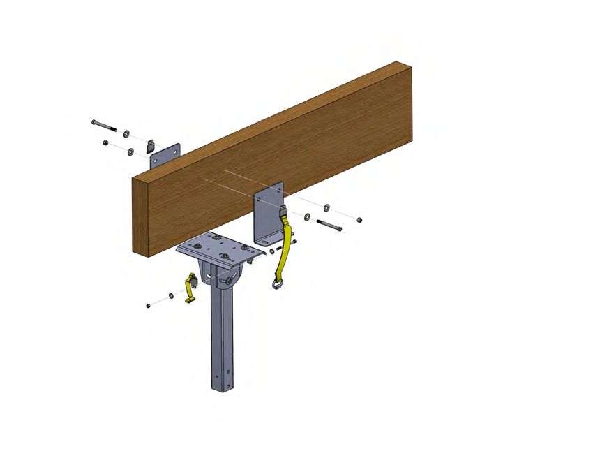
Recommended GFY®
                                                                                                                    Fan Clearances

                                              G
                                                                                      A
                                                                                                                                              Installation and Technical Operations
                                                                                                                                                                          Z-TECH™ FAN

                                                                                                                          F
                                                                                                                                          E
                           D
                                                                                            B
                    Guidelines
                    A. Clearance from solid roof surfaces or solid trusses:
                           i. 8, 10, 12 & 14ft fans = 4ft                         C       Legend
                          ii. 16, 18, 20, 22 & 24ft fans = 5ft

GO FAN YOURSELF ®
                            Open trusses do not need to be considered for air              A.   Distance from the ceiling
                            flow restriction.                                              B.   Distance of fan from tip to tip
                    B. Diameter of fan from tip to tip.
                    C. Fan diameter. Blades must be a minimum of 10' from the              C.   Distance from the floor
                       deck.                                                               D.   Distance from fan blades to outer
                    D. Should be equal to the diameter of the fan.                              walls
                    E. Should have at least 18" of clearance from obstructions.
                    F. Should not be less than 2 feet with any fan diameter.               E.   Distance from obstructions
                    G. The best practice is to keep blade tips 20ft from any
                                                                                           F.   Proximity of fan tip to roof with pitch
                       heat source or exhaust fan whenever possible.
                    H. Per NFPA fans must be centered between (4) sprinkler                G.   Heat Source
                       heads if the location is equipped with sprinklers.
                                                                                                                                                                                      |9
Z-TECH™ FAN | 10
Installation and Technical Operations
Follow the Factory Mutual Insurance Company (FM Global) standards, Heating equipment manufacturer’s guideline
and safety standards such as those published by the National Fire Protection Association (NFPA), and the American
Society for Heating, Refrigeration and Air Conditioning Engineers (ASHRAE), and local code authorities.
WARNING: A structural engineer will need to verify that the structure is suitable prior to the installation of the fan. The fan
should not be installed unless the structure on which the fan will be mounted is securely constructed, without damages, and can
support the load of the fan. It is the sole responsibility of the customer/end user to have the stability of the mounting
structure verified. Go Fan Yourself® hereby denies any liability resulting from the lack of verification or from the use of any
materials or hardware than those supplied by Go Fan Yourself ® or otherwise indicated within these installation instructions.
1. Tools Required to Install Product
• Level
• High torque 1/2" impact gun with impact socket set
• Torque wrench capable of 30 ft-lbs +/- 2 ft-lbs
• Standard socket set
• Standard wrench set
• Scissor or Boom Lift
2. Required Steps Before Installation
• Check to see if you have all the tools required for the installation.
• Verify that all fan components were received.
• Check drawings and layouts provided to locate where the Z-TechTM Fan is to be installed.
• Each person installing the Z-TechTM Fan must use a safety harness at all times.
• Other safety requirements may be required for installation.
• All workspace safety requirements and lock out/tag out procedures provided by the customer
for the assembly and installation of the Z-TechTM Fan must be met and followed.
Start your installation “I” Beam Mounting
Fig.2
3. Different Mounting Applications
Note: The following mounting applications
are representations only and are subject to
change without notice. Contact your sales
representative or the Go Fan Yourself ®
office for complete mounting instructions.
Insert optional shims (found in bottom tray
of your fan packaging) to keep Beam Clamp
Plates near level if I-Beam is thicker than
the bend in the Beam Clamp Plate. Shims
insert on top of the Upper Yoke Assembly
and are secured with the mounting
hardware. See picture above and following
pages for additional details.
GO FAN YOURSELF ®Z-TECH™ FAN | 11
Installation and Technical Operations
3. Different Mounting Applications
Bottom Chord Angle Iron Mount
Drill holes in angle iron and direct mount in
place of using Beam Clamp Plates.
Fig.3
NOTE: The 3"x3"x1/4"steel angles must be supplied
by the installer. Hardware used to secure the angles
to the mounting structure is not included.
NOTE: If the truss span is wider than 8 FT (4) steel
angles are required. Contact GFY ® for additional
instructions.
***NOTE*** Hardware A, B, and C below are contractor supplied.
A - (4) 1/2"x13x1.5" longer than the lower chord of the truss Grade 8 Cap Head Screw
B - (8) 1/2" Grade 8 Flat Washer
C - (4) 1/2"x13 Grade 8 Steel Nylock Nut
D - (1) GFY® Truss Mount Kit will be included with your fan (kit consists of (4) large square
washers). Tighten all hardware to a minimum of 40 ft lbs (54.2 N.m).
• Face angle irons as shown.
• Once mounted use Upper Yoke Weldment and mark
mounting holes on the angle irons.
• Drill (2) holes in each angle iron and direct mount the
Upper Yoke Weldment to the angle irons.
• The Beam Clamp Plates and shims are not used in this
application.
GO FAN YOURSELF ®Z-TECH™ FAN | 12
Installation and Technical Operations
3. Different Mounting Applications (continued)
Top Chord Angle Iron Mount
Drill holes in angle iron and direct mount in
place of using Beam Clamp Plates.
Fig.4
NOTE: The 3"x3"x1/4" steel angles must be
supplied by the installer. Hardware used to
secure the angles to the mounting structure
***NOTE*** Hardware A, B, and C below are contractor supplied: is not included.
A - (4) 1/2"-13x(chord height + 1.5") Grade 8 Cap Head Screw
B - (8) 1/2" Grade 8 Flat Washer
NOTE: If the truss span is wider than 8'
C - (4) 1/2"-13 Grade 8 Steel Nylock Nut
(4) steel angles are required. Contact GFY®
D - (1) GFY® Truss Mount Kit will be included with your fan (kit consists of
(4) large square washers). for additional instructions.
Tighten all hardware to a minimum 40 ft lbs (54.2 N.m).
• Face angle irons as shown.
• Once mounted use Upper Yoke Weldment and mark
mounting holes on the angle irons.
• Drill (2) holes in each angle iron and direct mount the
Upper Yoke Weldment to the angle irons.
• The Beam Clamp Plates and shims are not used in this
application.
GO FAN YOURSELF ®Z-TECH™ FAN | 13
Installation and Technical Operations
3. Different Mounting Applications (continued)
“L-Bracket” Mounting
(Refer to L-Bracket Installation
Guide) Fig.5
Secure L-Brackets
As shown below secure the L-Brackets and Safety
Clips with Carabiners to the mounting structure with
installer-supplied:
Contractor Supplied Required Hardware:
(2) 1/2"-13 x "1 1/2" longer than the support
structure" Grade 8 Hex Cap Screw
(4) 1/2" Grade 8 Flat Washer
(2) 1/2"-13 Grade 8 Steel Nylock Nut
Tighten all hardware to a minimum
40 ft lbs (54.2 N.m).
GO FAN YOURSELF ®Z-TECH™ FAN | 14
Installation and Technical Operations
3. Different Mounting Applications (continued)
“Z-Purlin” Mounting
(Refer to Z-Purlin Installation Guide)
Fig.6
1) Drill the Z-Purlins using the backer plate as a
template and anchor the backer plate to the
Z-Purlin Bracket with supplied hardware.
Tighten to a minimum 40 ft lbs (54.2 N . m).
2) Measure and pre-drill the angle irons for the
fan mount using the mount as a template.
3) Finger tight the angle irons facing outward to
hold them in place and attach the fan mount.
4) Tighten both the fan mount hardware and the
angle iron hardware to a minimum
40 ft lbs (54.2 N.m).
NOTE: Z-Tech Fans equipped with Z-Chill
must NOT mount to Z-Purlins with this kit.
They must be mounted directly to the main
beams and not on the Z-Purlins.
Mounting Hardware Supplied
a. (16) 1/2"-13 x 2” Grade 8 Hex Head Cap Screw
b. (32) 1/2" Grade 8 Flat Washer
c. (16)1/2" Grade 8 Nylock Nut
Tighten all hardware to a minimum
40 ft lbs (54.2 N.m).
GO FAN YOURSELF ®Z-TECH™ FAN | 15
Installation and Technical Operations
Beam Clamp Plates
4. Standard Mount
A Standard Mount is used for 6"-10" I-Beams and
all optional mounting kits. Down Tube is ordered
to length.
An optional XL Mount is used for 12"-15" I-Beams
and truss angle iron mounts when the truss span is Upper
greater than 8ft. This requires (4) 3"x3"x1/4" steel angles. Yoke
Contact GFY for more information. Weldment
The package includes:
(2) mfg “I” Beam Clamp Plates. Down Fig.7
Tube
(2) mfg “I” Beam Spacers (may or may not be
required for assembly)
(1) Upper Yoke Weldment*
Lower
Yoke
Assembly
*Down Tube and Lower Yoke are shown as a preview of the fan mount assembly
Installing the Mount
1. Secure the “I” Beam or OWSJ Beam between
the mfg “I” Beam Clamps and the Upper Yoke.
Insert the mfg “I” Beam Spacers if required.
2. Insert the bolts, washers and tighten to a
minimum 40 ft-lbs (54.2 N.m). (Fig 8)
Upper Yoke Mounting Hardware:
(4) 1/2"x13x2" Grade 8 Hex Cap Screw
(8) 1/2" ASTM F436 Type 1 Mechanical Galvanized Steel
Structural Flat Washer
Fig. 8
(4) 1/2"x13 Grade 8 Steel Nylock Nut
Tighten the bolts to a minimum 40 ft-lbs (54.2 N . m)
Insert optional shims (found in bottom tray of your fan
packaging) to keep Beam Clamp Plates near level to the
mounting surface of the I-Beam when the I-Beam is thicker
than the bend in the Beam Clamp Plate. Shims insert on top
of the Upper Yoke Assembly and are secured with the
mounting hardware.
Beam Clamp Plate
Shim
Upper Yoke Assembly
GO FAN YOURSELF ®Z-TECH™ FAN | 16
Installation and Technical Operations
5. Down Tube
This package includes:
(1) Down Tube
(standard 1ft, ordered to length)
(2) Z-Tech SSTM Upper Safety Straps
Fig. 10
Hardware Pack:
(4) 1/2"x13x5" Grade 8 Hex Cap Screw ***NOTE*** Down Tubes may be ordered in lengths
(8) 1/2"x1.375" Thru Hardened General from 1 FT to 10 FT. Longer than 3 FT the Down Tube
Purpose Flat Washer Kit will include a Guy Wire Kit that must be used to
(4) 1/2"x13iGrade 8 Steel Nylock Nut stabilize the fan during normal operation.
Installing Down Tube, Upper Safety Cable, &
Lower Yoke Assembly
1. Slide the upper end of the Down Tube (end with the
factory installed Z-TechSSTM Safety Straps) into the
Upper Yoke.
2. Loosely fasten the Down Tube into the Upper Yoke
by tightening the hardware only enough to engage
the nylock nut. This keeps the hardware in place while
allowing the self-leveling feature of the Upper Yoke to
work for you. Do NOT tighten until the Motor Hub
Assembly has been securely fastened to the Lower
Yoke on the bottom end of the Down Tube.
3. Wrap the upper Z-TechSSTM Safety Straps as tightly
as possible around the building structure and fasten
the loops with the shackle or 3/8" quick link provided.
4. Assemble the Lower Yoke onto the bottom of the
Down Tube. Tighten hardware to a minimum
40 ft-lbs (54.2 N.m).
5. The lower Z-TechTM SS Safety Straps will be secured to
the bottom on the Down Tube after the Motor Hub
Assembly is anchored to the Lower Yoke (see details
next page).
3/8" Quick Link Shackle
Fig.11
GO FAN YOURSELF ®Z-TECH™ FAN | 16A
Installation and Technical Operations
6. Z-TechTM SS Saftey System Makes GFY the safest fan on the market! Ships with
all GFY orders. A retrofit version is also available for existing GFY fans.
Route upper straps around building support.
Wrap as tightly as possibleand secure with
the shackle or 3/8" quick link provided.
Secure the lower straps to the Down
Tube with the hardware provided and
tighten to a minimum of 40 ft-lbs (54.2 N.m)
Hardware List:
(1) 3/8" x 4.5" Grade 8 Bolt
(2) 3/8" Grade 8 Flat Washers
(1) 3/8" x 16 Grade 8 Nylock Nut
GO FAN YOURSELF ®Z-TECH™ FAN | 17
Installation and Technical Operations
6. Main Hub and Drive Assembly
The package includes:
(1) Hub.
(1) Fan frame
(1) Motor
(1) Gearbox
Fig.12
Hardware Pack Includes:
(4) 1/2"x13x1.5" Grade 8 Hex Cap Screw
(8) 1/2" ASTM F436 Type 1 Mechanical Galvanized Steel
Structural Flat Washer - Grade 8
(4) 1/2"x13 Grade 8 Steel Nylock Nut
Mount & Upper Yoke
Installing the Main Hub & Drive Assembly
Down Tube & Lower Yoke
1. Raise the fan and align the Mounting
Plate with the Lower Yoke Assembly.
2. Fasten the top plate of the Fan Frame Motor Hub Assembly
to the Lower Yoke and tighten to a
minimum 40 ft-lbs (54.2 N.m)
3. Attach both Z-TechTM SS safety
straps to the down tube and secure
with the hardware provided (see Fig.
4. 11) Fig.13
Verify fan level by checking both Check fan level by placing the level
directions on the vertical post of the on the front and side of either
5. fan frame. vertical post of the fan frame.
Tighten the Upper Yoke/Down Tube
hardware to a minimum 40 ft-lbs
(54.2 N.m) to secure the fan level.
GO FAN YOURSELF ®Z-TECH™ FAN | 18
Installation and Technical Operations
7. Optional Guy Wires (standard when down tube longer than 3FT) I-Beam
Nut
The package includes: Eye Bolt
Washer
(4) Cable 1/8” Stainless Steel (4 @ 20 FT provided) Thimble
(8) Thimbles 1/4" Stainless Steel Nylock Nut
Cable Clamps
(16) Cable Clamps 1/8” (Use 2 per Anchor Location) Washer
(4) Turnbuckles 3/8” x 6” 1200# Galvanized eye to eye
Fig.14
(4) Quick Links 3/8" Guy Wire Cable
Contractor Supplied Hardware For Anchor Points:
(4) 3/8" eyebolts (1 1/2" longer than the thickness of the anchor point)
(4) Nuts 3/8"
(8) Washers 3/8"
(4) Nylock Nuts 3/8" Ceiling/Roof Deck
Guy Cables should
be snug, NOT tight.
Recheck fan level
after tensioning
Guy Wires
When placing cable clamps on
the wire it is critical the U-Bolt
side of the clamp is placed on
the short, turn-back end and
the saddle goes on the long
end running from the anchor
Fig.15 o o
point to the fan (see detail
45 to 60 below).
.
Guy Wires are not a safety int
mechanism. They prevent fan po
h or
oscillation when Down Tubes get nc
longer than 3FT. a
e
th
To
Tighten cable clamp hardware Fig.16
to a minimum 4.5 ft-lbs (6.1 N.m)
GO FAN YOURSELF ®Z-TECH™ FAN | 19
Installation and Technical Operations
Installing the Optional Guy Wires
1. Determine mounting position on ceiling and
establish the angle between 45º-60º for the
cable. Determine correct location on the I-
Beam to drill the hole for the eye bolt. For
example, if the guy wire anchor points on the
fan are 3' 4" (101.6 cm) down from the I-Beam
or Steel Angles the cables should anchor at
least 3' 4" (101.6 cm) away from fan.
2. Install an eye bolt with nuts and washers in I-
beam as per Fig. 14.
3. Measure the run of cable required and cut
approximately 2 FT longer. NOTE: runs longer
than 18 FT will require additional cable.
4. Secure it with 1 thimble and 2 cable clamps
(Fig.16). Repeat using the other 3 pieces of
guy wire cable, thimbles and cable clamps
Fig.17
5. (Fig.15) Guy wires should be snug but not
overstressed to allow free self-levelling. They
should also be approximately 90º apart
(Fig.17). NOTE: Fans hanging lower than 10ft from
where the guy wires will mount may require
additional cable (provided by the installer).
8. Z-TechTM Blade Assembly
(5) Blades Installing the Blade Assembly
(5) Blade Stabilizer Plate 1. Clamp blade between blade stabilizer
(15) 3/8"x16x3.5" Grade 8 Hex Cap Screw plate and hub.
(30) 3/8"x0.812"Grade 8 Flat Washer 2. Continue until all 5 blades have been
(15) 3/8"x16 Grade 8 Nylock Nut fastened and tighten to:
30 ft-lbs +/-2 ft-lbs
(40.7 N.m = 30 ft-lbs) or
(38 N.m to 43.4 N.m)
3. Turn the fan by hand and verify
minimum clearance exists for all
blades from all obstructions.
Fig.18
GO FAN YOURSELF ®Z-TECH™ FAN | 20
Installation and Technical Operations
9. Leveling the Fan
1. After your fan is installed, check the level again by placing your level vertically on the
vertical post of the fan frame. Adjust as required.
2. Once leveled, tighten hardware to a minimum 40 ft-lbs (54.2 N.m) to secure the Down Tube into the
Upper Yoke. Verify fan level once hardware is tightened.
Fig.19
ATTENTION! Motor Gearbox Vent Failure to remove the vent stopper will cause gearbox failure!!
1. Remove rubber stopper from the gearbox
2. Discard after removal.
ABB Dodge Motor Vent Plug
ABB Dodge vent
plug shown in
place. This must
be removed
before motor
operation.
Vent shown with
plug removed.
For proper electrical connection, please consult the Wire Connections (Motor) page later in this document.
GO FAN YOURSELF ®Z-TECH™ FAN | 21
Installation and Technical Operations
Electrical Installation
& Operation Manual
All installation wiring must confirm to your National Electrical Code and local guides. While
we believe that using Go Fan Yourself ®controls and following our instructions will result in an
installation that meets those requirements, we cannot guarantee it. Code
compliance is ultimately the installer’s and/or user’s responsibility.
Subject to change without notification.
IMPORTANT
Wind can flex fan blades a great deal. Increase blade clearance from 2 FT to anything
above the blades to 3 FT on all project where the fan may be exposed to the wind.
Safety Precautions
• All installations must be installed by a qualified person.
• Do not work on live equipment. Use lock out/tag out procedures.
CRITICALLY IMPORTANT!!
Upon completion of the installation you MUST complete the
GFY® Check In/Close Out Form and take two pictures:
1) The overall fan installation.
2) Close up of the fan mount clearly showing both safety cables routed properly, snug,
and secured with the hardware provided.
Please send the completed GFY® Check In/Close Out form and these pictures to
drew@gofanyourself.com
GO FAN YOURSELF ®Z-TECH™ FAN | 22
Installation and Technical Operations
Wire Requirements
• GFY recommends 600v 12 ga stranded wire for all 3 phase GFY installations.
• GFY recommends 600v 12 ga stranded wire for all 1 phase GFY installations.
• Size of input and output wires may go up based on length and current draw of VFD and motor.
• See Power Requirements (page after next) for current draw of VFD and motor.
VFD = Variable Frequency Drive
A separate insulated ground must be provided to each
VFD from the electrical panel.
Motor is rated with an Insulation Class H or F;
Ensure proper wiring is used as per current electrical codes.
Wet/Agricultural - PVC Conduit Wet/Agricultural - PVC Conduit
Dry (Industrial/Commercial) - EMT Conduit 3 Phase = shielded cable, inverter-rated,
(3) 12g Wires + Insulated Ground
3 Phase = (3) 12g Wires + Insulated Dry (Industrial/Commercial) - EMT
Ground 1 Phase = (2) 12g Wires + Insulated Conduit 3 Phase = (3) 12g Wires +
Ground Insulated Ground
Electric
Panel
VFD Motor
3 phase installations AC(PWM) 3ph
require minimum with 12g wires.
12g stranded wire.
***NOTE*** This run MUST be stranded
Single phase installations cable. Do NOT use solid cable.
require minimum
12g stranded wire.
GO FAN YOURSELF ®Z-TECH™ FAN | 23
Installation and Technical Operations
Maximum Cable Length
Table. Cable Length Between the VFD and Motor
100-120 VAC 1 Phase Max 200 ft No HP Change
200-240 VAC 1 Phase Max 200 ft No HP Change
200-240 VAC 3 Phase Max 200 ft No HP Change
380-480 VAC 3 Phase Max 200 ft No HP Change
If lengths beyond 200' are required the best practice is to order the optional "Wall Mount Keypad Kit' or
remove the keypad from the drive and mount the keypad to a 4x4 J-Box with a Drywall Ring. Some
onsite fabrication required.. Maximum CAT5 cable length is 300ft. Contact your salesperson or local GFY®
representative for more information.
For installations with cable lengths exceeding a 200' run from the VFD to the Motor please consult the
factory at: 1-844-GOFANME (463-2663).
The data cable connecting the keypad is very short and must be removed carefully
whenever the ABB VFD Case is opened.
1. Remove the (4) machine screws from the cover.
2. Reach in and press down on the data cable tab and gently unplug the keypad.
3. Remove the cable for the "two tab" strain relief system.
4. Place the cover in a safe location while work is being completed inside the drive.
To replace the cover once work is finished reverse the cover removal process.
1. Lift the cover up to the drive.
2. Being sure to leave enough slack in the data cable engage the "two tab" strain
relief system.
3. Gently plug the drive into the keypad. Be sure the cable seats securely.
4. Be sure the cover gasket is properly seated.
5. Fasten the cover with the (4) screws removed.
GO FAN YOURSELF ®Z-TECH™ FAN | 24
Installation and Technical Operations
Power Requirements
Required Line
Circuit Size
18ft, 20ft, 22ft & 24ft Fans
GFY-Z-XX-460 (fan powered by 380-480V 3 phase) = 3.5 amps - 10 amp
GFY-Z-XX-230 (fan powered by 200-240V 3 phase) = 7.0 amps - 10 amp
GFY-Z-XX-240 (fan powered by 200/240V 1 phase) = 15 amps - 20 amp
14ft & 16ft Fans
GFY-Z-XX-460 (fan powered by 380-480V 3 phase) = 2.15 amps - 10 amp
GFY-Z-XX-230 (fan powered by 200-240V 3 phase) = 4.3 amps - 10 amp
GFY-Z-XX-120 (fan powered by 100-120V 1 phase) = 18 amps - 30 amp
8ft, 10ft & 12ft Fans
GFY-Z-XX-460 (fan powered by 380-480V) 3 Phase = 1.94 amps - 10 amp
GFY-Z-XX-230 (fan powered by 200-240V) 3 Phase = 3.88 amps - 10 amp
GFY-Z-XX-120 (fan powered by 100-120V) 1 Phase = 15 amps - 25 amp
GO FAN YOURSELF ®Z-TECH™ FAN | 25
Installation and Technical Operations
Wire Location
• DO NOT RUN input and output power cables in the same conduit.
• DO NOT RUN control cables with any power cables in the same conduit.
• DO NOT RUN different fans output power cables in the same conduit.
• You can run different fans input power cables in the same conduit.
Minimum 1 FT
MUST be stranded
cable! Do NOT use
solid cable.
Input Power
• 3 Ph use L1 – L2 – L3 + PE
(Ground)
• 1 Ph use L1 – L2 + PE
(Ground)
Power In Power Out
From Panel To Fan
120VAC - L1 = Hot
- L2 = Neutral
240VAC - L1 = Hot
- L2 = Hot
NOTE: All single phase applications must be wired as 200-240VAC 3 phase applications from
the VFD controller to the fan motor. The controller will change the 1 phase power it is
receiving and supply 200-240VAC 3 phase power to the motor.
GO FAN YOURSELF ®GFY® Connection For ESFR Suppression System
ACS355 Controller - 200-240VAC & 380-480VAC 3 Phase Applications Only
1) Primary Method - The Control is designed to take a PNP
(Sourced) +24 VDC signal from an ESFR fire suppression
system. The ESFR system will supply the +24V DC power.
o Digital Input "DI3" (POS. 14) = +24V signal wire.
o DCOM (POS. 11) = 0V common signal wire.
Installation and Technical Operations
o The Drive will go in to an alarm condition when the
Z-TECH™ FAN
+24VDC signal is lost. Fan operation is prevented
and the Control will stay in the alarm condition
until the +24VDC signal is restored.
2) Alternate Solution - Run the output from Pin 9 (+24VDC)
to a relay and run the output from the relay to Pin 14
(Digital Input 3 "DI3"). Control the relay with the ESFR fire
suppression system.
GO FAN YOURSELF ®
+24 VDC ESFR Digital Input DCOM • If using the primary ESFR connection
method above both jumpers must be
+24VDC removed when the ESFR connection is
0 VDC DCOM From ESFR Circuit made to the drive.
• If using the alternate method only the
jumper from Pin 9 to Pin 14 is removed.
| 26Z-TECH™ FAN | 27
Installation and Technical Operations
GFY® Connection For ESFR Suppression System
ACS255 Controller - 100-120VAC & 200-240VAC Single Phase Applications
This diagram is designed to take a PNP (Sourced) +24 VDC
signal from an ESFR fire suppression system. The ESFR
system will supply the +24 VDC power.
Run the +24 VDC signal wire to terminal 4 and route 0V COM to
terminal 7. There should be room in the terminal block to
accept both wires on terminal 7.
To enable the ESFR signal input see the programming steps
below. The drive will go into a fault condition once the 24VDC
signal is lost and will not allow fan operation until that signal
is restored.
+24VDC COM
Programming Instructions for GFY ® ACS255 Controller - Enable ESFR Input
1) Once ESFR connection is complete from fire
suppression system. Power up the drive.
a) Display should say "SToP".
2) Hold "Enter/Select" for 1 second.
a) Drive will enter programming mode.
b) PAr S (parameter short list) should be
displayed.
c) Press "Enter/Select".
d) Display should show 4 digits (they may
be "0000").
3) Use Up/Down Arrow Keys and locate
parameter 9902.
a) Press "Enter/Select"to select.
4) Use Up/Down Arrow Keys to change parameter
9902 setting to "6".
a) Press "Enter/Select"to save.
b) Display should return to parameter 9902.
5) Press and hold "Enter/Select" until display
reads "StoP". You have exited programming
mode.
6) Drive will immediately fault if ESFR signal is
Enter/Select Up/Down missing.
Arrows
GO FAN YOURSELF ®Z-TECH™ FAN
Installation Electrical and Technical Operations
| 28
Wire Connections (Motor) ABB Dodge Motor
Always wire the motor per the wiring diagram on the inside of the motor cover plate.
All single phase applications MUST be connected as "Low Voltage".
Voltage Supply to the
ABB VFD Controller:
380-480VAC 3 Phase
Connect the motor for
High Voltage
Voltage Supply to the
ABB VFD Controller:
200-240VAC 3 Phase
200-240VAC 1 Phase
100-120VAC 1 Phase
Connect the motor for
Low Voltage
Low Voltage Wiring High Voltage Wiring
T1 to T7 and L1 (incoming 208-240 VAC) T1 to L1 (incoming 480VAC)
T2 to T8 and L2 (incoming 208-240 VAC) T2 to L2 (incoming 480VAC)
T3 to T9 and L3 (incoming 208-240 VAC) T3 to L3 (incoming 480VAC)
T4 to T5 and T6 (tie together) T4 to T7
T5 to T4 and T6 (tie together) T5 to T8
T6 to T4 and T5 (tie together) T6 to T9
T7 to T1 and L1 (incoming 208-240 VAC) T7 to T4
T8 to T2 and L2 (incoming 208-240 VAC) T8 to T5
T9 to T3 and L3 (incoming 208-240 VAC) T9 to T6
GO FAN YOURSELF ®Z-TECH™ FAN | 29
Installation and Technical Operations
Quick Operations Instructions for the VFD Controller ACS355 ABB Control
Local /
Remote
Indicator
To Change Direction: To Stop: To Start: To Change Speed:
Local / Remote - If keypad controlled may be in local or remote mode: LOC or REM
If controlled by a control system must be in remote mode: REM
LED Condition: Solid Green - Fan is ready for use.
Flashing Green - Fault detected. Fan may operate. Investigate fault and clear.
Flashing Red: Fault detected. Fan will not operate until fault is cleared.
GO FAN YOURSELF ®Z-TECH™ FAN | 30
Installation and Technical Operations
Quick Operations Instructions for the VFD Controller ACS255 ABB Control
Stop/Select Direction: Both Buttons Disabled
To Change Speed:
• The display will have an "H", indicating "Hertz". The frequency (or speed) the fan is turning will be
indicated numerically. H - 45.8 for example.
• The word "STOP" will be shown any time there is power applied to the drive but the fan is not
turned on. STOP indicates the fan is on and ready for use.
GO FAN YOURSELF ®Z-TECH™ FAN | 31
Installation and Technical Operations
Best Practices for General Fan Operation Using The ACS355 ABB Control
To Turn the Fan On:
• Turn the Lock Out/Tag Out disconnect in the lower left hand corner of the controller to the "ON" position.
o The disconnect turns fairly hard to avoid accidental movement.
• The ACS355 controller will go through a start up sequence.
• Once start up is complete the fan will show the home screen showing operational parameters:
o Hz - The value of hertz the variable frequency drive is sending to the motor.
o A - The amps the fan is drawing.
o % - The percentage of full speed the fan is currently running.
Initially after start up all these values should read "0".
To Start the Fan Spinning:
• Once the ACS355 controller has completed it's start up sequence as detailed above press the "Start" button.
o This will cause the fan to begin turning in the direction of and at the speed of its last setting when the
"Stop" button was pressed.
To change speed use the arrow buttons.
• Look at the number in the upper right hand corner of the display. This shows the Hz
value the fan is programmed to run at.
• Once you see the value of Hz you want the fan to run at release the arrow key.
o The fan will now ramp up or down to the new setting.
o The "Hz" display on the fan will show the actual ramp speed of the fan until it
reaches the new setting.
To Reverse Direction:
• Simply press the "DIR" soft key as indicated by your quick operations guide in this manual.
o The fan is programmed to ramp down until full stop is achieved for a split second and then
reverse direction and ramp up to the last speed it was running in the new direction.
To Remove Power From the Fan for Service Work:
• Press the stop button and wait for the fan to completely stop.
• Turn the disconnect to the "Off" position and perform Lock Out / Tag Out.
Best Practices for General Fan Operation Using The ACS255 ABB Control
To Turn the Fan On:
• Turn the Lock Out/Tag Out disconnect in the lower left hand corner of the controller to the
"ON" position.
o The disconnect turns fairly hard to avoid accidental movement.
• The ACS255 controller will go through a start up sequence.
• Once start up is complete the fan will display "SToP" indicating it is ready for use.
To Start the Fan Spinning:
• Turn the selector switch to "FWD" for cooling operation or "REV" for destratification only
operation.
• Adjust the speed of the fan with the dial selector.
To Reverse Direction:
• Simply turn the selector switch to "FWD" or REV" as indicated by your quick operations guide in this
manual.
o The fan is programmed to ramp down until full stop is achieved for a split second and then
reverse direction and ramp up to the speed indicated by the dial selector.
To Remove Power From the Fan for Service Work:
• Turn the selector switch to "0" and wait for the fan to completely stop.
• Turn the disconnect the the "Off" position and perform Lock Out / Tag
Out.
GO FAN YOURSELF ®Z-TECH™ FAN | 32
Installation and Technical Operations
Recommended Maintenance Schedule
1. No maintenance shall be done on the fan, mount or guy wires while in operation or powered. Complete
Lock Out/Tag Out measures on the fan before work is begun.
2. No maintenance shall be done on the fan controller while powered unless the task involves
reprogramming or troubleshooting the electrical system. Complete Lock Out/Tag Out measures on the
circuit before work is begun.
3. No maintenance shall be done within a 20ft horizontal radius of the fan and 4ft below and none above
the blade level while the fan is in operation.
4. While doing maintenance on the fan, mount, or guy wires, a safety barrier shall be erected at a radius of
20ft of the center of the fan.
5. The fan controller shall be locked out while maintenance is ongoing on the fan, mount, or guy wires.
6. All personnel working on the fan, mount, or guy wires, shall wear the appropriate personal safety
equipment as mandated by local, provincial, and national regulations.
7. A risk assessment shall be performed before any work is done. A checklist shall be completed and shall
include any emergency contacts for the area.
NOTE: Maintenance schedule is based on running 5,000 hrs/year and is a guideline to ensure safe and
continuous operation of the fan(s). In cases of extreme operation (e.g. high humidity, aggressive
environment, or large temperature variations), shorter intervals between service is recommended.
Safety Precautions
1. Z-TechSSTM Safety System installed per this Z-TechTM Fan installation manual.
2. Guy wires (if equipped) installed as per Fig. 14, 15, 16 & 17 in this Z-TechTM Fan installation manual.
3. Blade Stabilizer Plates installed as per Fig.18 in this Z-TechTM Fan installation manual.
4. See next page for required clearances.
5. If installed in storage facility between racks, signs must be installed identifying fan locations.
6. The ABB variable frequency drive has several safety features such as current limit, motor overload,
minimum, maximum and ramp speed control. The controller also features a LOTO disconnect all
housed within a NEMA 4X enclosure.
GO FAN YOURSELF ®Z-TECH™ FAN | 33
Installation and Technical Operations
Z-TechTM Fan Clearance Requirements
28" 30"
120"
Clearances
• Min 60” center of fan to roof deck for ideal operating performance without compromising
overall fan performance
• Min 24" from fan blade’s leading edge to obstruction above or below fan
• Min 18” from side of fan to any obstruction
• Min 120” floor to fan blade tip or lowest point of the fan
Contractor is responsible for verifying all site conditions to include field dimensions where applicable. If the contractor elects to make
any changes without notifying Go Fan Yourself ® the contractor is responsible for the same. All drawings are to be used as general
architectural intent unless otherwise stamped. See Engineer drawings for structural design information. Contractor to ensure
that all building departments and authorities are informed in regard to the work and that all permits are attained before
commencing work.
GO FAN YOURSELF ®Z-TECH™ FAN | 34
Installation and Technical Operations
GFY Annual Performance Plan
We're here to help you keep your warranty active and protect
your air movement investment!
Certified Services Performed
1) Integrity of safety system.
2) Verify blade connection.
3) Inspect hub, blades and Z-TechTM leading edges for proper operation.
4) Inspect ABB VFD parameters and performance.
5) Check fault log and record if any are reported.
6) Check ABB/Baldor motor performance & operation
7) Check ABB/Baldor gearbox performance & operation including breather (if equipped).
8) Integrity of electrical connections.
9) Check fan mounting structure and fan level and plumb.
10) Verify hardware connections.
11) Verify guy wire tension and inspect cables and connections (if equipped).
12) Visual inspection of equipment.
13) Enhance GFY equipment by adding Z-TechTM SS retrofit (Z-TechTM, Z-Tech3TM, Z-ChillTM only).
14) Document any customer observations.
15) And we even clean the fan!
It's EASY!!
1) Request a quote from GFY for your Annual Performance Plan: info@gofanyourself.com
2) Approve the Annual Performance Plan Quote and return to GFY
3) GFY will contactyou to schedule your Performance Plan
4) Check it OFF your To-Do list
5) Peace of MIND!
GO FAN YOURSELF ®GFY ANNUAL PERFORMANCE Go Fan Yourself ®
1032 National Parkway
PLAN CHECKLIST REQUIRED TO Schaumburg, IL 60173
1-844-GOFANME (463-2663)
MAINTAIN YOUR WARRANTY 1-847-648-4920
Email completed form and pictures to: info@gofanyourself.com www.GoFanYourself.com
Company:
Address: City/
State/Zip: Contact Name:
Email: Phone:
The performance plan outlined below will be completed on GFY® large diameter ceiling mount fans annually:
Fan(s) Number or Location:
1) Visual inspection of fan. (look for any sign of damage or unusual wear)
2) Check fan mounting structure and fan level and plumb.
3) Verify hardware connections.
4) Verify guy wire tension and inspect cables and connections. (if equipped, guy wires should be snug)
5) Inspect hub, blades and Z-TechTM leading edges. (look for any sign of damage or unusual wear)
6) Verify blade connection. (blade hardware to be torqued to 30 ft lbs +/- 2 ft lbs)
7) Check Integrity of safety system. (hardware is tight, straps show no signs of wear)
8) Check gearbox performance & operation including breather (if equipped). (fan should turn
easily by hand in both directions - no unusual noises or interruptions of smooth travel)
9) Check Integrity of electrical connections. (wire discoloration often means excess heat)
10) Check fault log and record any reported faults. Check motor performance & operation.
11) Document any observations with pictures and in "Notes" below.
12) Clean the fan with a mild detergent and/or clean water.
Take pictures and send to GFY along with this checklist(s) of the fan from the floor and close-
ups showing Z-TechTM SS properly installed at the motor/hub assembly and at the upper yoke
weldment.
Notes:
GFY® Annual Inspection Plan_2020Z-TECH™ FAN | 35
Installation and Technical Operations
GFY® Annual Performance Plan Record
Fan Location: Fan Location: Fan Location:
Fan Diameter: Fan Diameter: Fan Diameter:
Motor Serial Number: Motor Serial Number: Motor Serial Number:
Motor Size: Motor Size: Motor Size:
Fan Location: Fan Location: Fan Location:
Fan Diameter: Fan Diameter: Fan Diameter:
Motor Serial Number: Motor Serial Number: Motor Serial Number:
Motor Size: Motor Size: Motor Size:
Date Mechanic Signature Date Mechanic Signature Date Mechanic Signature
Date Mechanic Signature Date Mechanic Signature Date Mechanic Signature
Date Mechanic Signature Date Mechanic Signature Date Mechanic Signature
Date Mechanic Signature Date Mechanic Signature Date Mechanic Signature
Date Mechanic Signature Date Mechanic Signature Date Mechanic Signature
Date Mechanic Signature Date Mechanic Signature Date Mechanic Signature
Date Mechanic Signature Date Mechanic Signature Date Mechanic Signature
Date Mechanic Signature Date Mechanic Signature Date Mechanic Signature
GO FAN YOURSELF ®Z-TECH™ FAN | 36
Installation and Technical Operations
ACS355 CONTROL TROUBLESHOOTING
Troubleshooting Tips:
• If possible, swap the VFD control with another fan to isolate the problem.
Test the VFD Control:
• Remove power at the breaker supplying the control and perform Lock Out / Tag Out procedures.
• Disconnect the output power wires running from the VFD to the Fan Motor.
• Remove LOTO and restore power to the VFD.
• Turn the VFD on and watch for the proper start up sequence.
o "ABB" screen comes up for a few seconds.
o Fan "home" screen comes up showing fan performance.
• Operate the VFD as if the fan were connected.
o The VFD should work normally as the screen indicates VFD output, not fan operation.
If the VFD does not operate properly or faults/alarms are triggered the VFD should be
replaced.
Test the Motor Housing Assembly:
• Turn the fan off at the VFD Control and perform Lock Out / Tag Out procedures.
• Turn the fan by hand in both directions. The fan should turn easily in both directions. If it does not observe:
o Look for any mechanical interference between the blades/hub and the fan frame.
o Feel for grinding, the movement of the fan should be smooth and quiet.
o Listen for grinding or any metal on metal contact.
• The GFY gearmotor is a motor and gearbox. Anything that looks or sounds other than you'd expect from a
motor and gearbox is a likely indication of a problem. The Motor Housing Assembly should be replaced.
1) Depending on the fault received they may be two different reactions from the keypad LED:
a) Flashing Green indicating either:
i) Fire Alarm signal is currently being received and preventing the fan from operating.
ii) Minor fault that did not require the fan to shut down but requires an operator reset.
1) In this case the soft key "DIR" to reverse direction will change to "RESET".
a) Once "RESET" is pushed the fault will clear and the LED will return to solid
green.
b) A record of this fault may be retrieved from the "Fault Logger".
b) Solid Red indicating the alarm shown on the screen caused the fan to shut down.
Alarm 2023 "Emergency Stop" is shown below. This is caused by the Fire Alarm input. The LED will be Flashing Green.
Flashing Green LED
A "Fire Alarm" activation will read "Emergency
Stop" and will stay active until the input from the
alarm system is removed. This screen will toggle
with the Home Screen showing Hz, Amps, and %
of speed all reading zero.
You can create this alarm for testing purposes by
removing the jumper running from terminal
position 9 to 14.
Both jumpers must be removed once the Fire
Alarm connection is made.
GO FAN YOURSELF ®Z-TECH™ FAN | 37
Installation and Technical Operations
ACS355 CONTROL TROUBLESHOOTING
To retrieve or review a Fault:
1. Press "MENU" from the home screen.
2. Once in the Main Menu arrow to " Fault Logger".
(The list will start with the last menu selected. In this
case "PARAMETERS". Arrow down to "FAULT
LOGGER".
3. Press "Enter" to select "FAULT LOGGER".
GO FAN YOURSELF ®Z-TECH™ FAN | 38
Installation and Technical Operations
ACS355 CONTROL TROUBLESHOOTING
4. Review the list of faults. The list is organized
with the most recent fault at the top.
Press "DETAIL" to see additional information
about the fault selected.
5. Arrow up and down to see the desired
information.
Hit the "DIAG" button for troubleshooting tips.
These tips assume the drive and fan have been
operating successfully and do not pertain to
common installation faults in most cases.
6. Arrow up and down to review the
diagnostic information and troubleshooting
tips.
Press "Exit" to leave the diagnostic
information.
GO FAN YOURSELF ®Z-TECH™ FAN | 39
Installation and Technical Operations
ACS355 CONTROL TROUBLESHOOTING
2001 - Output current from the drive to the motor has exceeded the trip level.
• Check the integrity and connections of the motor power wires running from the drive to the fan.
• Verify drive input voltage is grounded on the "PE" terminal lug and the motor power voltage is grounded to one
of the "Ground" terminal lugs.
• Spin the fan by hand. It should move freely in both directions.
o If you cannot spin the fan by hand the motor may be seized up and must be replaced.
o If the fan moves easy in one direction and much more difficult in the other direction the motor must be
replaced.
• Motor may be nearing the end of it's useful life. All motors may draw more current as they age. This motor may
be gradually failing to the point of drawing more current than the drive can supply. It must be replaced.
2002 - Input voltage has too much noise and must be conditioned in front of the drive.
• Place a commercial line reactor on the input power wires supplying the drive.
• Verify drive input voltage is grounded on the "PE" terminal lug and the motor power voltage is grounded to one
of the "Ground" terminal lugs.
2003 - Input voltage trouble.
• Most common problem is a dropped phase of the 200-240 3 phase or 380-480 3 phase line
voltage.
2006 - Control signal is not being received by remote drive.
• This fault message should only be possible when your application is controlling multiple drives (fans) from a
single keypad. When controlling drives remotely from another keypad the signal from the controlling keypad
is sent through a wired connection to the remote drive. This signal is not being received.
• Check the wire connections in the terminal blocks of the drive with the fault code and the previous drive in line.
• Check the integrity of the low voltage control wire connecting the drives.
2008 - Drive has lost communication with the keypad.
• Swap keypads with another drive to isolate the fault.
o The keypad connector is fragile. Take care when breaking and making the connection.
• Verify keypad wire integrity.
o Use a spare data cable to isolate if it's the cable or the output from the drive.
2026 - Input phase loss.
• Line voltage supply to the drive has dropped a phase.
See the ACS355 manual you received with your fan shipment for greater details.
GO FAN YOURSELF ®Z-TECH™ FAN | 40
Installation and Technical Operations
ACS255 CONTROL TROUBLESHOOTING
Symptom Troubleshooting Steps
Fan Turning Wrong Direction For cooling (forward) operation the stepped edge of the blade should be the
leading edge. When running in destratification only (reverse) mode the
stepped edge of the blade should be trailing. You will feel no (or very little)
airflow when the fan is running in reverse. Reverse two of the phases either
at the control or at the motor to reverse fan direction.
Fan Will Not Start 1) Turn off the fan at the LOTO Disconnect on the face of the drive.
2) Wait ten seconds.
3) Reapply power and watch the drive go through it's normal start up sequence.
a) ABB shows on the screen for a few seconds.
b) Fan stats ("H" Hertz, "A" Amp Draw, "%" Speed)
4) If control boots up properly and fan will not turn remove power from the drive
and turn the fan by hand in both directions. Fan should move easily in both
directions.
5) Check power connections in all locations of the drive and motor.
6) Be sure input power in the drive is grounded to "PE" and output power from
the drive is grounded to either of the two ground terminals next to "PE".
Fan Wobbles During Operation Fan mounting structure is not rigid enough to support normal fan
operation. Verify the fan is not being exposed to external air movement.
If the fan downtube is longer than 3 FT guy wires are required to
stabilize the fan. If guy wires are installed verify proper installation.
Fault No. Description Corrective Action
Code
SToP 0x00 Drive is READY and in a stopped condition. The motor is not energized. No enable signal is present to start the drive.
Fault occurs immediately on drive enable or run command
Check the output wiring connections to the motor and the motor for short circuits phase to
Instantaneous Over current on phase and phase to earth.
the drive output. Fault occurs during motor starting
F0001 0x03
Excess load or shock load on the Check the motor is free to rotate and there are no mechanical blockages.
motor. Fault occurs when motor operating at constant speed
Investigate overload or malfunction. The motor may be nearing the end of it's useful life. All
motors draw more current as they age. This motor may need to be replaced.
Check the wiring to motor and the motor for phase to phase and phase to earth
short circuits. Disconnect the motor and motor cable and retest. If the drive trips
F0004 0x05 Hardware Over Current
with no motor connected, it must be replaced and the system fully checked and
retested before a replacement unit is installed.
External trip ESFR Fire Relay circuit is tripped. See the Installation and Technical Specifications
F0014 0x0B
(on digital input 3) Guide for additional information including required programming.
F0022 0x0E Input phase loss trip Drive intended for use with a 3 phase supply has lost one input phase.
The incoming supply voltage is too low. This trip occurs routinely when power is
F0006 0x07 Under voltage on DC bus removed from the drive. If it occurs during running, check the incoming power
supply voltage and all components in the power feed line to the drive.
See the ACS255 manual you received with your fan shipment for greater details.
GO FAN YOURSELF ®Z-TECH™ FAN | 41
Installation and Technical Operations
ACS255 CONTROL TROUBLESHOOTING
Troubleshooting Tips:
Test the VFD Control:
• Remove power at the breaker supplying the control and perform Lock Out / Tag Out procedures.
• Disconnect the output power wires running from the VFD to the Motor.
• Remove LOTO and restore power to the VFD.
• Turn the VFD on and watch for the proper start up sequence.
• Operate the VFD as if the fan were connected.
o The VFD should work normally as the screen indicates VFD output, not fan operation.
If the VFD does not operate properly or faults/alarms are triggered the VFD should be
replaced.
Test the Motor Housing Assembly:
• Turn the fan off at the VFD Control and perform Lock Out / Tag Out procedures.
• Turn the fan by hand in both directions. The fan should turn easily in both directions. If it does not
observe:
o Look for any mechanical interference between the blades/hub and the fan frame.
o Feel for grinding, the movement of the fan should be smooth and quiet.
o Listen for grinding or any metal on metal contact.
• The GFY gearmotor is a motor and gearbox. Anything that looks or sounds other than you'd expect
from a motor and gearbox is a likely indication of a problem. The Motor Housing Assembly should be
replaced.
The image below shows a control
during normal fan operation.
Speed Control
Stop/Direction Selector Switch
Integral LOTO Disconnect
These buttons are disabled Enter/Select
Up/Down Arrows
GO FAN YOURSELF ®Z-TECH™ FAN | 42
Installation and Technical Operations
ACS255 CONTROL TROUBLESHOOTING
1. Press "Enter" and hold for 1 second until the
"Parameters" screen appears. "PAr L" or "PAr S"
will be displayed.
2. To observe the last recorded fault enter the "long"
parameter list.
3. Use the arrows to toggle between the long and
short parameter list.
PAr L = Long Parameter List
PAr S = Short Parameter List
See ACS255 Manual for Greater Detail
4. Default parameter setting shown. Press
the up arrow to move to parameter set
0401.
5. Parameter set 0401 details the last fault
recorded by the drive. The ACS255 only records
the last fault created.
6. Press "Enter" to see the last fault.
Last recorded fault displayed.
Press "Enter" for longer than 1 second to return
to the home screen.
GO FAN YOURSELF ®You can also read