UPLINK IOT NETWORKS: TIME-DIVISION PRIORITY-BASED NON-ORTHOGONAL MULTIPLE ACCESS APPROACH
←
→
Page content transcription
If your browser does not render page correctly, please read the page content below

Preprints (www.preprints.org) | NOT PEER-REVIEWED | Posted: 29 March 2021                            doi:10.20944/preprints202103.0709.v1

        Uplink IoT Networks: Time-Division Priority-Based
            Non-Orthogonal Multiple Access Approach
                     Basem M. ElHalawany∗† , Ahmad A.Aziz El-Banna∗† , Wali Ullah Khan‡ , and Kaishun Wu∗
                       ∗ College of Computer Science and Software Engineering, Shenzhen University, Shenzhen, China.
                                          † Faculty of Engineering at Shoubra, Benha University, Egypt
                            ‡ School of Information Science and Engineering, Shandong University, Qingdao, China

                           Emails: {basem.mamdoh, ahmad.elbanna, wu}@szu.edu.cn, waliullahkhan30@gmail.com

           Abstract—Non-orthogonal multiple access (NOMA) has been            multiple access (CDMA). However, OMA techniques provide
        investigated to support massive connectivity for Internet-of-         a great improvement, they can not afford the expected massive
        things (IoT) networks. However, since most IoT devices suffer         deployment in 5G and B5G networks. To tackle this challenge,
        from limited power and decoding capabilities, it is not desirable
        to pair a large number of devices simultaneously, which en-           non-orthogonal multiple access (NOMA) have been proposed
        courages two-user NOMA grouping. Additionally, most existing          [3]. Unlike OMA techniques, NOMA-based networks can
        techniques have not considered the diversity in the target QoS        serve multiple users using the same resources by exploiting
        of IoT devices, which may lead to spectrum inefficiency. Few          either the transmit power domain [4], [5] or code domain [6]–
        investigations have partially considered that issue by using an       [8], which leads to better performance and spectral efficiency
        order-based power allocation (OPA) approach, where the power
        is allocated according to the order to the user’s target throughput   compared to OMA. The focus of this work is to propose a
        within a priority-based NOMA (PNOMA) group. However, this             spectrum-efficient scheme for IoT systems, where users show
        does not fully capture the effects of diversity in the values of      a diversity in their QoS target throughput.
        the users’ target throughputs. In this work, we handle both
        problems by considering a throughput-based power allocation           A. Background and Related Work
        (TPA) approach, that captures the QoS diversity, within a three-
        users PNOMA group as a compromise between spectral efficiency            In power-domain NOMA, super-position coding is used
        and complexity. Specifically, we investigate the performance          at the transmitter and successive interference cancellation
        of a time-division PNOMA (TD-PNOMA) scheme, where the                 (SIC) at the receiver [4]. Two types of power-domain NOMA
        transmission time is divided into two-time slots with two-users       have been investigated in literature, namely the conventional
        per PNOMA group. The performance of such TD-PNOMA is                  NOMA (CNOMA) and the quality-of-service (QoS) based
        compared with a fully PNOMA (F-PNOMA) scheme, where
        the three users share the whole transmission time, in terms           NOMA (QNOMA), which is also known as priority-based
        of the ergodic capacity under imperfect successive interference       NOMA (PNOMA). In CNOMA, users are ordered and allo-
        cancellation (SIC). The results reveal the superiority of TPA         cated powers proportional to their channel gains [9], [10]. It
        compared with OPA approach in both schemes, besides that the          is noteworthy that there are two limitations of CNOMA: (i) In
        throughput of both schemes can outperform each other under            the two-users CNOMA, which is the widely-used arrangement
        imperfect SIC based on the transmit signal-to-noise ratio and
        the deployment scenarios.                                             due to its reduced decoding complexity at the receiver, a
           Index Terms—Non-orthogonal multiple access, priority-              cell-center (CC) user is usually paired with a cell-edge (CE)
        ordering, spectrum sharing, time-division.                            user. However, the number of CC and CE users may not be
                                                                              identical, which leads to a spectrum loss since some users are
                               I. I NTRODUCTION                               left unpaired and served using conventional OMA schemes,
           Recently, the wireless traffic has been growing rapidly            and (ii) In multi-users CNOMA, if two or more users have
        and is expected to grow several folds in the beyond fifth             similar channel gains (i.e., collocated users), these users can
        generation (B5G) networks. Different promising applications           not be paired in one group with other users [11]. The authors
        and services have been proposed underlaying 5G such as real-          in [11] considered a pairing scheme at which two similar-
        time high-definition video broadcasting, massive deployment           gain CE users are paired on a time-sharing basis with a single
        of machine-to-machine (M2M) communications and Internet-              CC user to avoid pairing two similar-gain users in one group.
        of-Things (IoT) services [1]. With this huge demand of                However, it is not possible to use CNOMA or time-sharing
        resources, spectral efficiency becomes a critical aspect for          CNOMA if the three users have similar-gains.
        managing the access to the core network [2]. Several mul-                On the other hand, users are assigned powers proportional
        tiple access techniques have been investigated for exploiting         to their priority or the order of their target throughput within
        the spectrum to face the congestion problem. In the fourth            the PNOMA group [12]–[17], which is known as order-
        generation (4G) of wireless networks, different orthogonal            based power allocation (OPA). However, there is a gap in the
        multiple-access (OMA) technologies have been proposed such            literature regarding the performance of PNOMA, specially that
        as orthogonal frequency division multiple access (OFDMA),             OPA approach does not capture the effects of the diversity in
        time-division multiple access (TDMA), and code-division               the values of the users’ target throughputs. In [16], the authors

            © 2021 by the author(s). Distributed under a Creative Commons CC BY license.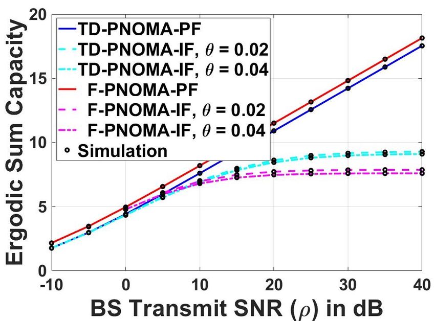
Preprints (www.preprints.org) | NOT PEER-REVIEWED | Posted: 29 March 2021                        doi:10.20944/preprints202103.0709.v1

        investigated the outage probability of a downlink PNOMA
        transmission in an overlay device-to-device (D2D) network,
        where a D2D transmitter is communicating with a group of
        collocated D2D receivers with different target rates. In [14],
        the secrecy performance for a two-users NOMA system is
        evaluated, where one user is prioritized over the other user.
        In [17], the authors have investigated a downlink PNOMA
        system with randomly deployed users. Specifically, they have
        investigated the asymptotic behavior of the outage probability
        and ergodic capacity at high signal-to-noise ratio (SNR).
                                                                           Fig. 1: (a) Time-division priority-based NOMA (TD-
        B. Motivations and Contributions
                                                                           PNOMA) Scheme. (b) Fully priority-based NOMA (F-
           Although the work in [12]–[17] have laid foundations for        PNOMA) Scheme.
        PNOMA schemes, there are many gaps in the literature to
        fully understand the challenges and implications for adopting         The rest of the paper is organized as follows: In section
        PNOMA. As an example, in contrast to the work in [16] that         II, the network model of the proposed scheme is presented.
        investigate PNOMA in a downlink D2D model, where all               Then, we derive the exact ECs for TD-PNOMA scheme.
        receivers have similar-gains under perfect SIC conditions, this    Section IV shows discussion about the feasibility of achieving
        work investigates an uplink model under imperfect SIC, where       NOMA gain and propose a throughput-based power allocation
        users may have similar or different-gains. it is noteworthy        technique. Analytical and simulation results are introduced in
        that the similar-gain model is applicable in a clustered IoT       section IV. Finally, the paper is concluded in section V.
        environment at which multiple IoT devices are collocated
                                                                                              II. N ETWORK M ODEL
        within a small area that can not be paired under CNOMA
        limitations, while the different-gain model can be used when          In this work, we investigate the performance of an arbitrary
        the users are not in close proximity.                              uplink OFDMA-based scenario at which three IoT users, with
           Several research work have considered M -users NOMA             different QoS target rates, share one resource block (RB) and
        models as in [17], however, increasing the number of users         transmit information to a base station (BS) located at the
        per resource block may not be feasible due to practical            center of the cell. Recently, many research work have investi-
        implementation and hardware limitations in IoT networks.           gated OFDMA-based networks, where each RB is assigned
        For the sake of balance between decoding complexity and            to a NOMA group of two-users to reduce the complexity
        improving the spectral efficiency, we analyze the performance      associated with SIC. In this work, we assume three-users
        of a time-division PNOMA (TD-PNOMA) scheme, where                  NOMA groups as a compromise between improving the
        three-users with different target rate/throughput, namely the      spectral efficiency and increasing complexity. We assume a
        high, mid, and low-rate users form a PNOMA group. The              diversity in the QoS target rates of IoT users in the network,
        transmission time is divided into two time-slots with two users    which can be classified into three regions represented by
        sharing each slot, assuming that the high-rate user participates   the high-rate (HR), mid-rate (MR), and low-rate (LR) users.
        in both slots to achieve the higher target rate. The main          We assume that hH , hM , and hL represent the channels
        contributions in this work can be listed as follows                between the BS and the three users. All channels are as-
           • Investigate the performance of an uplink time-division        sumed to be independent identically quasi static with Rayleigh
             PNOMA (TD-PNOMA), where three users with different            distribution, which are drawn according to the distribution
                                                                                     −q/2    1/2
             target rates share the same resource block.                   CN (0, di      P Lo ), where di is the distance between the
           • Derive closed-form expressions of the uplink ergodic          nodes and the BS, i ∈ {H, M, L}, respectively, q is the
             capacities (ECs) under imperfect SIC as a function of         path-loss exponent, and P Lo is the path-loss constant. We
             the target rates.                                             also assume that perfect channel state information (CSI) is
           • Investigate the performance of the proposed scheme un-        available.
             der different deployment scenarios to find if TD-PNOMA           In this work, we study the performance of a TD-PNOMA
             could pair users with different QoS target rates under        scheme and compare it with the F-PNOMA scheme, that
             similar or different gain conditions                          are shown shown in Fig.1. In TD-PNOMA scheme, the
           • Investigate the performance of traditional order-based        transmission time (T ) is divided into two time-slots. HR is
             power allocation (OPA) compared to a proposed                 paired with MR and LR for α T and (1 − α) T seconds,
             throughput-based power allocation (TPA) scheme.               respectively, while the transmit power is divided into σ P and
           • Compare TD-PNOMA to a fully-PNOMA (F-PNOMA)                   (1−σ) P , respectively, where α and σ are the time and power
             scheme, where all of the three users share the same           split ratios. The justification of such arrangement is that HR
             resource block for the whole time.                            needs to achieve higher target rate than MR and LR. On the
           • The accuracy of the analytical results is verified through    other hand, the three nodes form a three-users PNOMA group,
             numerical simulation.                                         which are served using the same time and frequency in the
Preprints (www.preprints.org) | NOT PEER-REVIEWED | Posted: 29 March 2021                         doi:10.20944/preprints202103.0709.v1

        F-QNOMA scheme as shwon in Fig. 1b. In the following, the             Ergodic Capacity Analysis: The EC of        R ∞a transmission
        spectral efficiency of the proposed scheme is investigated and     can be mathematically defined as Cγ = 0 t B log2 (1 +
                                                                                             tB
                                                                                                  R ∞ 1−Fγ (x)
        quantified in terms of the ergodic capacity, which is derived      x) fγ (x) dx = ln(2)                dx, where t are the transmis-
                                                                                                   0      1+x
        under imperfect and perfect SIC conditions, where the ergodic      sion time, fγ (x) and Fγ (x) is the probability density function
        capacity (EC) determines the maximum data transmission rate.       (PDF) and the cumulative distribution function (CDF) of the
           Since HR has higher target rate than both MR and LR, the        SINR γ, respectively. In the following, we introduce Theorem
        power allocated to HR is larger than these allocated to both       1, which is used for deriving the ECs of the three users.
        MR and LR, such that φM < φH1 , φL < φH2 , φM +φH1 = 1,               Theorem 1: The ergodic capacity of a transmission with
        and φL + φH2 = 1, where φH1 and φM are the power                   SINR γ = ZZ    1
                                                                                              is given by
                                                                                        2 +1
        allocation factors in the first time-slot, φH2 and φL are the                            −t B Ωz1
        power allocation factors in the second time-slot. Consequently,              Cγ = ln(2) Ω −Ω          η (Ωz1 ) − η (Ωz2 ) ,      (4)
                                                                                                  ( z1 z2 )
        the signals received at the BS during the first and the second
                                                                           where B, t denote the bandwidth and duration, η(x) =
        time-slots due to the simultaneous uplink transmissions of           1
                                                                           e x Ei −1x , Ei is the exponential integral function (8.211.1)
        each pair are given as follows
                 p                      p                                  in [18], Z1 and Z2 are exponentially-distributed random
           y1 = PT 1 φH1 hH XH1 + PT 1 φM hM XM + n1 , (1a)                variables with parameters Ωz1 and Ωz2 , respectively.
                 p                        p
           y2 = PT 2 φH2 hH XH2 + PT 2 φL hL XL + n2 . (1b)                    Proof: The
                                                                                       R ∞EC   of the transmission can be evaluated as
                                                                                            1−Fγ (x)
                                                                                   tB
                                                                           Cγ = ln(2)   0     1+x    dx, where Fγ (x) = Pr{ ZZ        1
                                                                                                                                    2 +1
                                                                                                                                         < x}
        where XM , XL , XH1 , and XH2 denote the information               is the CDF of γ which can be expressed as follows
        symbols transmitted from MR, LR, and HR on the two                                  R ∞ R x (1+z2 )
        time-slots, respectively with the expectations E{|XM |2 } =                Fγ (x) = 0 0             fZ1 (z1 ) fZ2 (z2 )dz1 dz2
                                                                                                      Ωz1        −x                        (5)
        E{|XL |2 } = E{|XH1 |2 } = E{|XH2 |2 } = 1, PT 1 = σP ,                            = 1 − Ωz +Ωz x e Ωz1
                                                                                                      1    2
        and PT 2 = (1 − σ)P are the transmit powers at the two             where Ωz1 , Ωz2 are the average power of the exponentially-
        time slots, n1 and n2 are the complex additive white Gaussian      distributed random variables Z1 , and Z2 , respectively, fZ1 (z1 )
        noises (AWGN) at the BS at the two time-slots. Since HR has        and fZ2 (z2 ) are the PDFs of Z1 and Z2 , respectively. Using
        a higher priority than MR/LR during the first/second time-slot,    (5), partial fractions’ expansion, and integral identity (4.352.4)
        the BS must decode the message XH1 /XH2 first then uses SIC        in [18], Cγ can be re-casted into (4), which completes the
        to decode the message XM /XL . Assuming an imperfect SIC,          proof.
        the signal-to-interference-plus-noise-ratios (SINRs) at the BS        By using Theorem 1, the closed-form expressions of ECs
        are given respectively as follows                                  for the three nodes under imperfect and perfect SIC conditions
                               σ ρ φH1 |hH |2                              are given in lemma 1 and lemma 2, respectively.
                      γH1 =                                        (2a)       Lemma 1: The ergodic capacities of the three nodes in
                             σ ρ φM |hM |2 + 1
                                σ ρ φM |hM |2                              TD-PNOMA Scheme under imperfect SIC are given as
                       γM =                                        (2b)                −B

                                                                                                  α ΩH1
                             θ σ ρ φH1 |hH |2 + 1                               T
                                                                             CH =                           (η (ΩH1 ) − η (ΩM o ))
                              (1 − σ)ρ φH2 |hH |2                                     ln(2) ΩH1 − ΩM o
                      γH2 =                                        (2c)                       (1 − α)ΩH2

                             (1 − σ)ρ φL |hL |2 + 1                                        +               (η (ΩH2 ) − η (ΩLo ))         (6a)
                                 (1 − σ)ρ φL |hL |2                                           ΩH2 − ΩLo
                        γL =                           ,           (2d)                     −α B ΩM o
                             θ (1 − σ)ρ φH2 |hH |2 + 1                       CMT
                                                                                  =                           (η (ΩM o ) − η (θ ΩH1 )) (6b)
                                                                                      ln(2) (ΩM o − θ ΩH1 )
        where ρ = P/No denotes the transmit signal-to-noise ratio
                                                                                         −(1 − α) B ΩLo
        (SNR), No is the AWGN noise power spectral density at the            CLT =                           (η (ΩLo ) − η (θ ΩH2 )) , (6c)
        BS, |hH |2 , |hM |2 , and |hL |2 are the channels gains which                 ln(2) (ΩLo − θ ΩH2 )
        follow exponential distribution with the parameter Ωi =               where T refers to the TD-PNOMA scheme, ΩH1 =
        P Lo d−q
               i   for i ∈ {H, M, L}, and θ is the residual interference   σ ρ φH1 ΩH , ΩH2 = (1 − σ)ρ φH2 ΩH , ΩM o = σ ρ φM ΩM ,
        power ratio due to imperfect SIC, which is assumed to be the       and ΩLo = (1 − σ)ρ φL ΩL , respectively.
        same for all users without loss of generality. Given the SINRs        Proof: Since the four SINRs in (2) have similar structure
        in (2), the achievable data rates of the three nodes at the two    as γ, Theorem 1 can be used to complete the proof by
        time slots are given as follows                                    considering the different parameters of the SINRs.
                                                                              Lemma 2: The ergodic capacities of the three nodes in
                           RH1 = α C(γH1 )                         (3a)    TD-PNOMA Scheme under perfect SIC are given as follows
                           RH2 = (1 − α) C(γH2 )                   (3b)                     C̄HT     T
                                                                                                  = CH                                   (7a)
                            RM = α C(γM )                          (3c)                             −α B
                                                                                               T
                                                                                            C̄M   =       η (ΩM o )                      (7b)
                            RL = (1 − α) C(γL ),                   (3d)                             ln(2)
        where B is the bandwidth, C(x) = B log2 (1 + x), the total                                  −(1 − α) B
                                                                                             C̄LT =            η (ΩLo ) ,                (7c)
        rate achieved by HR is given as RH = RH1 + RH2 .                                               ln(2)
Preprints (www.preprints.org) | NOT PEER-REVIEWED | Posted: 29 March 2021 doi:10.20944/preprints202103.0709.v1
Proof: By setting θ to zero in (6), we get the proof after By investigating the gain feasibility in this subsection, we
some simple mathematical manipulations. can present the following Lemma.
Lemma 3: The possibility to achieve PNOMA gain for a
III. T HROUGHPUT-BASED P OWER A LLOCATION two-user group not only depends on the target rates (i.e., R̄1
In this section, we provide discussions on the the differ- and R̄2 ) but also on the channel gains (i.e., |h1 |2 , |h2 |2 ).
ences between the order-based (OPA) and the throughput- Proof: By substituting the proposed TPA coefficients in
based (TPA) power allocation techniques, and feasibility of (9) into the feasibility condition in (10), we can see that the
achieving PNOMA gain. satisfaction of the feasibility condition depends on both the
OPA versus TPA: In [17], the OPA coefficients for target rates and the channel gains not the target rates only. In
PNOMA scheme are computed based on the order of the other words, the previously introduced intuition, that not all
user’s throughput within the K-users PNOMA group, which deployment scenarios (i.e., the relative values of the channel
are given as follows gains or simply the relative distances with respect to the BS)
can achieve PNOMA gain, is true.
K − r[i] + 1
φOPA
i = , (8) IV. R ESULTS AND D ISCUSSIONS
µ
In this section, we verify the correctness of the derived
where K is number of the users in the group, r[i] is the
ECs and the improvement for the proposed TPA scheme
PKuser i, and µ is a constant which is selected
order of the
compared to the OPA scheme via simulation. For the sake of
such that i=1 φOPA i = 1. In this subsection, we propose a
completeness of the work, we provide performance analysis of
throughput-based power allocation (TPA) technique, at which
the fully-PNOMA scheme for a three-users PNOMA group.
the power coefficient (φH1 , φH2 , φM , and φL ) rely on the
Via those simulations, it is possible to identify which scheme
actual value of the target throughput of the user not the order
is suitable for different deployment scenarios. Fig. 1b shows
of its throughput. The TPA coefficients for a K-users PNOMA
the time and power distribution of the F-PNOMA scheme.
group can be expressed as
The three users are served together during the whole time
R̄i period (T ), while the power is divided between the three users
φi = PK , (9) according to their priority/target rates (i.e. βH > βM > βL )
i=1 R̄i
and βH +βM +βL = 1. We assume that the channels between
where R̄i is the target rate of ith user. The intuition behind (9) users and BS undergo both small-scale fading and path-loss
is that the power allocation coefficients should maintain that effect. Small-scale fading follows an exponential distribution
the highest order user would have the highest SINR among with a mean value of 1. The noise signal of all channels
all users and simultaneously reflect the diversity on the values has a Gaussian distribution with zero-mean and unit-variance.
of those target throughputs. The path-loss exponent (q) and the path-loss constant P Lo
Intuitively, the power allocation based on both OPA or TPA are set to 3 and 0.1, respectively. We assume a normalized
can be applied in uplink scenarios if the users are collocated bandwidth (i.e., B = 1 Hz). Unless otherwise mentioned, we
or the user nearer to the BS is the one with higher target assume the target throughputs of the three users to be 1, 0.5,
throughput. However, if the near user have higher target and 0.25 bps/Hz. Under the previous assumption, the power
throughput and power, this will lead to situations where the allocation factors of the order-based power allocation (OPA)
received powers from different users are comparable at the settings and TD-PNOMA scheme are {φH1 , φM , φH2 , φL } =
BS, which compromise the SIC process. { 32 , 13 , 23 , 13 }, while the coefficients of the F-PNOMA scheme
Feasibility of Achieving PNOMA Gain: In this sub- are {βH , βM , βL } = { 21 , 13 , 16 } according to (8). On the other
section, we seek the conditions under which the pairing hand, for the investigated throughput-based power allocation
of two users with different target rates can be paired for (TPA) scheme, the power coefficients of the TD-PNOMA
uplink PNOMA scenario and achieve PNOMA gain (i.e., scheme are {φH1 , φM , φH2 , φL } = { 32 , 13 , 45 , 15 }, while the
the sum rate of the two users in PNOMA scheme is better coefficients of the F-PNOMA scheme are {βH , βM , βL } =
than the OMA scheme). By assuming two ordered uplink { 47 , 27 , 17 } according to (9). We assume equal sharing for the
users, U1 and U2 , with power coefficients φ1 > φ2 which two time slots in TD-PNOMA scheme, where α = σ = 0.5.
are used in both PNOMA and OMA, U2 always achieves The performance of the two investigated PNOMA schemes
higher rate at PNOMA than OMA (R2P N OM A > R2OM A ), are compared in terms of EC in a cell of 500 m radius under
where R2P N OM A = log2 (1 + ρ φ2 |h2 |2 ) and R2OM A = the following deployment scenarios: (i) HML Deployment:
0.5 log2 (1 + ρ φ2 |h2 |2 ). On the other hand, U1 can achieve where HR location is the nearest to the BS, then MR, then LR
gain if (R1P N OM A > R1OM A ), where R1P N OM A = log2 (1 + is the farthest, and (ii) HLM Deployment: where HR location
ρ φ1 |h1 |2 OM A is the nearest to the BS, then LR, then MR is the farthest, and
ρ φ2 |h2 |2 +1 ) and RH = 0.5 log2 (1 + ρ φ1 |h1 |2 ). After
some mathematical manipulation, the condition needed to (iii) where LMH Deployment: LR location is the nearest to
achieve gain for PNOMA scheme is given as follow the BS, then MR, then HR is the farthest, and (iv) Co-located
Deployment: where the three users are in close proximity to
1 + ρ φ1 |h1 |2 > (ρ φ2 |h2 |2 )2 . (10) each others.Preprints (www.preprints.org) | NOT PEER-REVIEWED | Posted: 29 March 2021 doi:10.20944/preprints202103.0709.v1
(a) (a)
(b) (b)
Fig. 3: Sum ergodic capacity versus the transmit SNR (ρ) for
both OPA and TPA power allocation schemes under HML
deployment for θ = 0.04. (a) Target thresholds are 1, 0.25,
0.1 bps/Hz (b) Target thresholds are 1, 0.5, 0.25 bps/Hz.
of the system, defined as the sum of the ergodic capacities
of the three users, versus the BS transmit SNR (ρ) under
under different deployment scenarios and different residual
power factors of SIC (i.e., θ ∈ {0, 0.02, 0.04}) for the two
schemes (TD-PNOMA and F-PNOMA) assuming the conven-
tional OPA power allocation. Each sub-figure represents one
(c) of the pre-mentioned deployment scenarios. Fig. 2 shows a
common behavior for all deployments, where the sum ECs
of both schemes under perfect SIC conditions (TD-PNOMA-
PF and F-PNOMA-PF) are monotonically increasing with ρ,
while under imperfect SIC conditions (TD-PNOMA-IF and F-
PNOMA-IF) the sum ECs curves tend to saturate at different
values, according to θ, as ρ increases due to the residual
interference. The results also show a degraded performance
under imperfect SIC conditions for both schemes compared
to the perfect SIC case.
Regarding choosing the suitable scheme for different de-
ployment scenarios, we have the following observations: (i)
(d) The F-PNOMA-PF scheme outperforms all other schemes
Fig. 2: Sum ergodic capacity versus the transmit SNR (ρ) for including its counterpart TD-PNOMA-PF scheme in all de-
the OPA power allocation. (a) HML (b) HLM (c) LMH (d) ployment scenarios. However, both HML and HLM scenarios
Co-located Deployment. shows comparable performance gap between F-PNOMA-PF
and TD-PNOMA-PF in Fig.2a and Fig. 2b, while this gap
shows a slight increase for the co-located deployment in Fig.
Fig. 2 shows the variations of the sum ergodic capacity 2d and becomes bigger for the LMH deployment in Fig. 2c.Preprints (www.preprints.org) | NOT PEER-REVIEWED | Posted: 29 March 2021 doi:10.20944/preprints202103.0709.v1
(2) The performance of both F-PNOMA and TD-PNOMA deployments scenarios of the three users. Moreover, the simu-
under imperfect SIC conditions can outperform each other in lation results show that it is not enough to consider the target
all deployment scenarios according to the transmit SNR (ρ). rates alone to achieve a gain in PNOMA, since the deployment
Still HML and HLM show a comparable performance, where scenario matters too.
TD-PNOMA-IF can outperforms F-PNOMA-IF staring from
ACKNOWLEDGMENT
threshold value ρ = 8 dB. On the other hand, this threshold
value elevates to 20:25 dB and 30:32 dB in co-located and This research was supported in part by the China
LMH deployment, respectively according to the value of θ. It NSFC Grant (U2001207, 61872248), Guangdong NSF
is noteworthy that these variations in the performance, special 2017A030312008, Shenzhen Science and Technology Foun-
those of LMH deployment, go along the intuition that not dation (No. ZDSYS20190902092853047), the Project of
every deployment and target throughputs can give a good DEGP (No.2019KCXTD005), the Guangdong “Pearl River
performance as mentioned in Lemma 3. Talent Recruitment Program” under Grant 2019ZT08X603.
Figure 3 compares the performance of both OPA and TPA Kaishun Wu is the corresponding author.
power allocation schemes in HML deployment assuming that
R EFERENCES
θ = 0.04 for the imperfect SIC cases. Figure 3a shows the
[1] M. Shirvanimoghaddam, M. Dohler, and S. J. Johnson, “Massive non-
ergodic capacity versus ρ assuming the target rates are 1, 0.25, orthogonal multiple access for cellular IoT: Potentials and limitations,”
and 0.1 bps/Hz while Fig. 3b assumes the rates are 1, 0.5, and IEEE Commun. Mag., vol. 55, no. 9, pp. 55–61, 2017.
0.25 bps/Hz. In both figures, we can see that the proposed TPA [2] B. M. ElHalawany, O. Hashad, K. Wu, and A. S. T. Eldien, “Uplink
resource allocation for multi-cluster internet-of-things deployment un-
power allocation improves the performance under both perfect derlaying cellular networks,” Mobile Netw Appl., vol. 25, p. 300–313,
and imperfect SIC conditions. However, the performance gap Jun 2020.
increases in Fig. 3a where the target throughput differences [3] Y. Saito, Y. Kishiyama, A. Benjebbour, T. Nakamura, A. Li, and
K. Higuchi, “Non-orthogonal multiple access (NOMA) for cellular
between HR and both other users increases (i.e., (0.75, 0.9) future radio access,” in Proc. IEEE VTC Spring, Jun 2013, pp. 1–5.
compared to (0.5, 0.75)). This behavior is similar to traditional [4] Z. Chen, Z. Ding, X. Dai, and R. Zhang, “An optimization perspective
NOMA where the achievable gain increases with increasing of the superiority of NOMA compared to conventional OMA,” IEEE
Trans. Signal Process., vol. 65, no. 19, pp. 5191–5202, Oct 2017.
the difference between the channel gains of NOMA-paired [5] A. Li, Y. Lan, X. Chen, and H. Jiang, “Non-orthogonal multiple access
users. (NOMA) for future downlink radio access of 5G,” China Communica-
Complexity Analysis: By grouping three IoT devices in tions, vol. 12, no. Supplement, pp. 28–37, Dec 2015.
one NOMA group, we improve the spectral efficiency of the [6] H. Nikopour and H. Baligh, “Sparse code multiple access,” in Proc.
IEEE PIMRC, Sep 2013, pp. 332–336.
network by slightly increasing the complexity at some of the [7] M. Moltafet, N. M. Yamchi, M. R. Javan, and P. Azmi, “Comparison
nodes. In F-PNOMA, the low priority user (LR) is the one that study between PD-NOMA and SCMA,” IEEE Trans. Veh. Technol,
needs to detect one extra message, while HR and MR retain vol. 67, no. 2, pp. 1830–1834, Feb 2018.
[8] L. Dai, B. Wang, Y. Yuan, S. Han, C. l. I, and Z. Wang, “Non-orthogonal
the same complexity compared with the two-users NOMA multiple access for 5G: solutions, challenges, opportunities, and future
grouping. On the other hand, HR needs to detect its own signal research trends,” IEEE Commun. Mag., vol. 53, no. 9, pp. 74–81, Sep
at the first and second time slots of the TD-PNOMA, while 2015.
[9] Z. Ding, P. Fan, and H. V. Poor, “Impact of user pairing on 5G
both MR and LR must detect HR’s message first similar to nonorthogonal multiple-access downlink transmissions,” IEEE Trans.
the two-users NOMA grouping. Veh. Technol, vol. 65, no. 8, pp. 6010–6023, Aug 2016.
Future Analysis: It is imperative to consider an efficient [10] H. Zhang, D. K. Zhang, W. X. Meng, and C. Li, “User pairing algorithm
with SIC in non-orthogonal multiple access system,” in Proc. IEEE ICC,
optimization algorithm to improve the performance in the in- May 2016, pp. 1–6.
vestigated TD-PNOMA system by searching optimal settings [11] M. Shahab and S. Shin, “A time sharing based approach to accommodate
for the power allocation factors, σ, and α. Additionally, it similar gain users in NOMA for 5G networks,” in Proc. IEEE LCN
Workshops, Oct 2017, pp. 142–147.
may be helpful to consider multi-carrier system, where users [12] Y. Xiao, L. Hao, Z. Ma, Z. Zhang, and Z. Fang, “Time and power
are grouped, assigned sub-carriers, and powers to improve the allocation for non-orthogonal multiple access relaying networks,” in
whole system performance. Proc. IEEE PIMRC, Oct 2017, pp. 1–5.
[13] Z. Ding, H. Dai, and H. V. Poor, “Relay selection for cooperative noma,”
V. C ONCLUSION IEEE Wireless Communic. Lett., vol. 5, no. 4, pp. 416–419, Aug 2016.
[14] D. D. Tran and D. B. Ha, “Secrecy performance analysis of QoS-based
In this work, we have investigated priority-based NOMA non-orthogonal multiple access networks over Nakagami-m fading,” in
spectrum sharing for uplink in IoT networks. Three users Proc. SigTelCom, Jan 2018, pp. 187–191.
are allowed to use the same resource block as a compromise [15] D. Tweed, M. Derakhshani, S. Parsaeefard, and T. Le-Ngoc, “Outage-
constrained resource allocation in uplink NOMA for critical applica-
between spectral efficiency and decoding complexity for IoT tions,” IEEE Access, vol. 5, pp. 27 636–27 648, Dec 2017.
devices with limited capabilities. We have considered two [16] A. Anwar, B.-C. Seet, and X. J. Li, “Quality of service based NOMA
main schemes, the time-division PNOMA and the fully- group D2D communications,” Future Internet, vol. 9, no. 4, Nov 2017.
[17] Z. Ding, Z. Yang, P. Fan, and H. V. Poor, “On the performance of
PNOMA, under perfect and imperfect successive interference non-orthogonal multiple access in 5g systems with randomly deployed
cancellation. Additionally, we compared two power allocation users,” IEEE Signal Proc. Lett., vol. 21, no. 12, pp. 1501–1505, Dec
techniques, namely the order-based (OPA) and the throughput- 2014.
[18] I. Ryzhik and I. Gradshteyn, Table of integrals, series, and products,
based (TPA) power allocation techniques. The results shows 7th ed., A. Jeffrey and D. Zwillinger, Eds. Academic Press, 2007.
that both schemes can outperform each others under differentYou can also read