University of Southern California
Concrete Canoe Design Paper 2013
←
→
Page content transcription
If your browser does not render page correctly, please read the page content below
University of Southern California Concrete Canoe Design Paper 2013

Table of Contents
Section Page
Executive Summary ii
Project Management 1
Organization Chart 2
Hull Design and Structural Analysis 3-4
Development and Testing 5-6
Construction 7-8
Project Schedule 9
Design Drawing 10
Figure Page
Figure 1: Canoe cross sections depicting bending
moments 3
Figure 2: Plan and profile views of the canoe used for
hand calculations. 4
Figure 3: Testing apparatus for reinforced slabs. 5
Figure 4: A carbon fiber-reinforced slab after
undergoing testing. 6
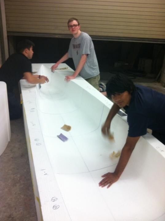
Figure 5: Construction team members sanding down
7
the mold.
Figure 6: A section of the foam mold before cutting
7
and sanding.
Table Page
Table 1: Quick facts about SC Traveler. ii
Table 2: Man-hours worked 1
Appendices
A - References
B – Mixture Proportions
C – Bill of Materials
i
Executive Summary
       The University of Southern                       build on their knowledge and experience
California (USC) is one of the world’s                  from the previous year to make
leading private research universities                   significant improvements to the canoe.
located in the heart of Los Angeles,                    Having two captains lead the team
California. It first opened in 1880 to 53               allowed effective combination of skills
students, and has since grown to                        and allocation of duties. This dual
accommodate 38,000 undergraduate                        leadership also allowed for an expedient
and graduate students. In addition to the               design and construction process, and
Andrew and Edna Viterbi School of                       also allowed flexibility in scheduling
Engineering, USC is also home to 19                     activities necessary to build the canoe.
other diverse schools of learning                       Twenty ASCE members were actively
ranging from the Keck School of                         involved in the project, spending most of
Medicine to the Thornton School of                      their time in ASCE dedicated to
                                                        constructing the concrete canoe. Since
 Table 1: Quick facts about SC Traveler.                USC is co-hosting the Pacific Southwest
               Concrete Properties                      Conference in 2013, the concrete canoe
 Compressive Strength (28 Day)         1850 psi         team decided to theme the canoe after
                                                    3
 Unit Weight                           63.2 lb/ft       their beloved university. The name of
                  Reinforcement                         the canoe, SC Traveler, comes from
 Carbon Fiber
                                                        USC’s mascot, Traveler, a white horse
             Design Specifications
                                                        that appears at all USC football games
 Length                        19.5’
                                                        in the Los Angeles Memorial Coliseum.
 Weight                        240 lb*
                                                        School spirit is an important part of the
 Max Depth                     14”
                                                        culture at USC, and the team felt that
 Hull Thickness                0.5”
                                                        since USC is co-hosting PSWC, sharing
 Max Beam Width                30”
                                                        this culture through the concrete canoe
 *Estimated weight.
                                                        would greatly complement our duties as
                                                        hosts.
Music. In the Viterbi School of
Engineering specifically, the Sonni
Astani     Civil   and     Environmental
Engineering        department         has
approximately     232     undergraduates
enrolled. In past competitions, USC has
done quite well, placing first for canoe
design in 1984 and 1985. In 1986, we
came in first place for construction. This
year, the team retained both captains
from the previous year, allowing them to

                                                                                              ii
Project Management
       The 2012-2013 USC Concrete                ruptured during competition. This step
Canoe team was led by two co-captains,           was completed by December 1st, 2012,
Jake Hermle and Erin Khan. Both                  after which all materials necessary for
captains returned to their positions from        pouring day were acquired, including the
the previous year, and because of that           foam mold. These materials were
were able to make improvements based             procured by January 15th, 2013, and the
on     knowledge        and     Table 2: Man-hours worked         canoe was cast on
experience gained last                            Total man-      February 3rd. The canoe
                                Project Phase
year. Jake focused on                                hours        will be removed from the
mix                 design,      Mold  Design          40         mold and sanded by
reinforcement, material           Mix Design           100        March 2nd, and the
                                   Material
procurement,            and                            35         staining and sealing of
                                 Procurement
budgeting, while Erin            Construction          410        the    canoe     will  be
oversaw mold design,           Paddling Practice       160        completed by March 18th.
construction,                  Total man-hours         745        A estimated total of 745
communications,         and                                       man hours will have been
paddling practices.                              spent on the design and construction of
       This year, the team was fortunate         the canoe upon its completion.
to be working with a larger budget than                  In order to ensure the quality of
the previous year. This extra money              our final product, the team used its
enabled us to purchase a new mold,               experienced members on hand to check
carbon fiber reinforcement, and new              all design and construction decisions.
materials to test and use in mix design.         Rigorous testing regimens were applied
       The critical path of the project          to concrete mixes and reinforcement
was determined by all tasks that needed          materials to ensure that we understood
to be completed in a certain                     their     material      properties.    For
chronological order in order for the             construction, the captains set up
canoe to be finished on time. The first          meetings before pour day to ensure all
step was the selection of the mix design         team members were aware of their
and method of tensile reinforcement.             tasks during casting. On pour day,
The first three months of the academic           multiple team members monitored
year were spent testing and tweaking             construction to ensure that we
mix designs meant to improve upon the            maintained proper methods. In addition
weaknesses of the previous year’s                to these quality assurance practices, the
canoe.      In    addition,   the     team       team maintained a standard of safety by
experimented           with       different      always wearing the proper equipment.
reinforcement materials to determine             During all interactions with the concrete,
which would be best for the canoe after          team members wore N95 respirators as
last year’s aluminum reinforcement               well as nitrile gloves.

                                                                                        1
Organization Chart
2Hull Design and Structural Analysis
Hull Design bow and stern rocker – the team
ascertained that it was not necessary to
The baseline design of the hull design for this, since the canoe is not
was the design of last year’s canoe, required to break the water’s surface
which was the standardized hull design during the flotation test.
from the 2009-2011 ASCE National
Concrete Canoe Competition. The team Structural Analysis
decided, however, that it would be best
to shrink down some of the dimensions. For the structural analysis of SC
While the canoe still needed to be able Traveler we relied heavily on the
to hold four paddlers, we decided we methods used to analyze the USC
could afford to shorten the canoe by 6 concrete canoes of 2009 and 2010 –
inches. We also decreased the since they were the most recent canoes
maximum width from 32” to 30”. This will with strong structural integrity, we used
decrease the canoe’s resistance against the same structural requirements used
forward movement in the water. for them. We created load cases and
Additionally, the decreased length and load combinations with an average
maximum width will decrease the overall paddler being about 150 pounds. When
weight of the canoe will make it easier to we were required to assume material
paddle during the races. The added strength, we used an assumed sitrength
benefit of a smaller canoe is that it is of 1000 psi. We then assumed that the
easier to maneuver, decreasing the risk canoe cross-sections were made of flat
that comes with transporting it. beams rather than curves, making it
The hull maintains a thickness of easier to perform structural analysis
0.5” inches throughout its entire surface,
consisting of three layers of placed
concrete. The first layer is .125” thick,
followed by a layer of carbon fiber
reinforcement. The middle layer is .25”
thick so that the tensile reinforcement
has a greater moment arm to provide
strength to the concrete. The middle
layer is followed by another layer of Figure 1: Canoe cross sections
carbon fiber and a final .125” layer of depicting bending moments
concrete. Although we have indicated a
thickness of ½”, it is likely that the hull is without the aid of advanced 3D
slightly thicker along the floor of the modeling. Based on our calculations of
canoe, as people have a inclinationto what the maximum loads on the canoe
pack more concrete onto the flat bottom would be, the canoe requires a
on casting day. compressive strength of 600 psi. Based
SC Traveler exhibits a depth of on past experience, however, the team
14 inches. This dimension is reduced used a required strength of 1100 psi, a
from the previous year’s 16 inches, also number that would be used as a target
with the goal of reducing overall weight. strength during mix design testing. In
The hull design incorporates 0 inches of our calculations we focused mainly on
3Hull Design and Structural Analysis
Based upon our hand-calculated
value of f’c, we should expect to design
concrete with a compressive strength of
170.75 psi. Many of the assumptions
made for this calculation, however, do
not reflect the potential uses of the
canoe. The 150lb user weight is
Figure 2: Plan and profile views of the variable, as is any torsional forces
canoe used for hand calculations. caused by turning the canoe during
the irregular loads that the canoe will racing. In previous years, the
experience during transportation as the conservative estimate of f’c = 1100psi
worst-case scenario in terms of applied has been used. Based on our
stresses. Furthermore, at the beginning calculations, 1100 psi is a sufficient
of the year we used the principles of target strength, as it far exceeds our
Load and Resistance Factor Design to calculated values.
approximate by hand the structural
demands for the concrete canoe. It is
important to note that this analysis was
done early on in the design phase, when
the exact dimensions of the canoe were
unknown and the mix design was in
progress. Assuming the live load was
150 pounds (weight of the average
paddler), and an approximated 140-
pound self weight of the canoe was
considered as the dead load,
calculations were performed with the
canoe simulated as a concrete beam.
Please see diagrams for assumptions
and specifications used.
LRFD Calculations:
C=0.85f’cbamax(ACI 10.2.7.1)
Muc=C(d-amax/2)Φ (Compression
resisted by concrete)
Mpoint loads = 315 lb-ft
Mdistributed load = 0 (continuous
support of the water resists all moment)
Mfactored = 378 lb-ft
f’c = 170.75 psi
4Development and Testing
Every year, the USC Concrete The highest priority during mix
Canoe team’s goal is to improve the design was improving workability and
canoe based upon the lessons learned wetness. The baseline mix started off
from last year’s mistakes. After PSWC with a mix that had a water to cement
2012, team leadership assessed certain ration of 0.5 and contained 50%
factors that needed improvement with aggregates by volume. When creating
regard to the actual design of the canoe. this mix (accordingly nicknamed
One of the most important “Flubber” afterward) in the lab, the team
improvements called for was stronger found the mix had too high of a slump,
tensile reinforcement. In 2012 the and needed to adjust the mix design.
aluminum mesh used to reinforce the The amount of aggregates by volume
canoe tore when it could not handle the was adjusted to slightly above 60% and
loads being placed on it. In addition, the water content was slightly reduced.
there were improvements needed in the The next mix had significantly less
mix design: it needed to be less dry and slump, but was still not up to the team’s
more workable. This was called for standards. Using their knowledge
because when placing the concrete for gained from a Mechanics of Materials
The Mystery Canoe (the USC 2012 class at USC, the team maintained the
canoe), team members placed layers volume of aggregates but increased the
thicker than the designed-for ¼” amount of “coarse” aggregates in the
because it was too difficult to place in mix – in this case, the “coarse”
thin layers. These thicker layers aggregates were 1-2mm sized Poraver,
significantly increased the overall weight the largest size aggregate. Changing
of the canoe, making it more difficult to the coarse-to-fine aggregate ratio
maneuver in the water while also reduced to slump to a level that satisfied
placing further stress on the the design team. Over the next few
reinforcement. The concrete mix also iterations of the mix design, the team
needed to be less dry. The Mystery fine-tuned the ratios of water, cement,
Canoe mix design was grainy on the coarse and fine aggregates while adding
surface and crumbly at some corners. in fibers to add extra tensile
The concrete also did not completely reinforcement.
bond across the open area of the
reinforcement. This led to delamination
and increased small-scale cracking,
which caused seepage in last year’s
canoe. The mix design team
started with a baseline that used the
same materials as the 2009 USC
Concrete Canoe, but with completely
changed proportions.
The team also omitted some of
the aggregates used in 2009 in order to Figure 3: Testing apparatus for reinforced slabs.
simplify the design and make it easier to
isolate ingredients that affect different After last year’s problems using
characteristics of the canoe. aluminum reinforcement, the team went
5Development and Testing
through a rigorous process to determine again as tensile reinforcement would be
the changes that needed to be made to putting the canoe at bigger risk than the
the canoe’s tensile reinforcement. While other two materials.
the aluminum reinforcement was Although the steel-reinforced slab
inexpensive and easy to work with, it did exhibited the greatest bending strength,
not provide the requisite strength the other factors had to be taken into
canoe demanded. The weakness of the consideration when choosing the
reinforcement compounded with the reinforcement material. The team
largesse of The Mystery Canoe caused members performing the tests reported
it to bough initially, then rupture near the that they experienced difficulty when
end of the races. working with the steel mesh – it was
The three materials the team extremely difficult to bend, meaning it
experimented were steel, carbon fiber, would also be difficult to bend when
and aluminum, which was tested in placing it in the mold on casting day.
order to provide comparison to the The team had had enough difficulties
previous year’s canoe. For each working with the aluminum in previous
material, three 4” x 12” x ½” years, and the steel proved
concrete slabs were cast to be even more resistive to
with a section of bending into the curves and
reinforcement placed corners of the canoe’s hull.
between two ¼” layers of Ultimately, this was what led
concrete. Since the carbon the team to go away from
fiber grid sheets were light using steel as the
and thin, two layers of reinforcement for SC
reinforcement were placed Traveler.
1/8” away from the top and Since steel and
bottom surfaces of the slab, aluminum had been ruled
with a ¼“ layer of concrete out as reinforcement
between them. The slabs material, the team chose the
were allowed to cure for 14 Chomarat C12 1.5” x 1.5”
days, then underwent a 3- carbon fiber grid. It provided
point bending test (see adequate strength while also
figure 3) in a SATEC being extremely light and
Universal Testing Machine Figure 4: A carbon fiber- easy to handle. Despite the
(UTM) to determine the slabs’ reinforced slab after fact that one can bend the grid
flexural strength. undergoing testing. sheets like a sheet of paper,
After testing all of the the material has an extremely
samples, it was clear that carbon fiber high tensile strength, which when
and steel contributed significantly more combined with the concrete creates a
tensile strength to the concrete than high resistance to bending stresses.
aluminum. The aluminum-reinforced While carbon fiber has the highest per
slabs had an average ultimate bending unit cost of the three tested materials,
strength of 560 psi, while carbon fiber this year’s larger budget meant the team
and steel exhibited strengths of 1012 psi could more easily afford it.
and 1392 psi. Clearly, using aluminum
6Construction
Form Material Selection
This year we decided to again use a
female foam mold. The female mold
allows us to obtain the correct canoe
dimensions when we place concrete on
the mold. We used polystyrene foam
because it is easily rough-cut with the
hotwire; and after this initial rough-cut,
we can make finer alterations with
simple sandpaper.
Form Construction
The polystyrene foam arrived in
2-foot long rectangular sections that
were 24” high to accommodate the Figure 6: A section of the foam
deepest part of the canoe and 36” wide mold before cutting and sanding.
to accommodate the widest section of foam section, we used a hotwire to cut
the canoe. Using templates for the out a female foam mold. Once all the
forward end and aft end taken from our sections had been cut, we assembled
the complete female mold by taping
together the sections with duct tape.
Upon inspection of the female
mold, we found several flaws that
would’ve yielded a poor quality finished
product. We therefore used a variety of
methods including taping over cracks
and hand-sanding down disconformities
to achieve a uniform quality throughout
the hull.
Placement of Concrete
Our concrete was placed over a
single pour day in order to reduce the
risk of failure at construction joints. This
required us to recruit a large pour day
Figure 5: Construction team team. In order to ensure we had
members sanding down the mold. enough attendance on pour day, we
sought to collaborate with other PSWC
CAD model, we were able to sketch out teams such as environmental and steel
the hull cross section on both ends of bridge as well as other USC civil
each section. Then, after securing each engineering student organizations such
7Construction
as Institute of Transportation Engineers
(ITE) and Construction Management
Association of America (CMAA). One
team of two students including the mix
designer spent the entirety of the day
batching concrete and ensuring
accurate weights of input materials while
the rest of the students mixed concrete
by hand and placed it in the female mold
using trowels when necessary.
Concrete Finishing
At the conclusion of pour day, we
placed the canoe and female mold
under plastic wrap and placed two
humidifiers inside the plastic wrap to
ensure a high degree of humidity while
the concrete cured. After three weeks,
the canoe was removed from the mold
and staining began. The aesthetics
team stained the canoe with a
combination of water- and acid-based
stains. The team let the canoe sit for
one week more before finally applying
two layers of sealant.
Sustainability and Project
Innovations
The SC Traveler incorporates
recycled material in its mix design.
Poraver, one of the aggregates used in
the mix, is made of recycled glass. By
using recycled material, the team
reduced the canoe’s impact on the
environment. The team also increased
efficiency by gathering volunteers from
other civil engineering clubs on pour
day. By increasing the number of man-
hours available to us, we reduced the
amount of time it took to finish casting
the canoe.
82012-2013 USC Concrete Canoe Schedule: Planned
9/30
10/7
10/14
10/21
10/28
11/4
11/11
11/18
11/25
12/2
12/9
12/16
12/23
12/30
1/6
1/13
1/20
1/27
2/3
2/10
2/17
2/24
3/3
3/10
3/17
3/24
2/31
4/4-6
9/16
9/23
9/2
9/9
Design
Canoe Hull
Mix
Reinforcement
Build
Mold
Stands
Winter Break
Spring Break
Transport Container
Canoe Construction
Pour Concrete
Curing Time
Sanding
Staining & Sealing
Non-Technical
Paper
Poster Board
Presentation
Paddling Practice
Competition
PSWC
2012-2013 USC Concrete Canoe Schedule: Actual
9/30
10/7
10/14
10/21
10/28
11/4
11/11
11/18
11/25
12/2
12/9
12/16
12/23
12/30
1/6
1/13
1/20
1/27
2/3
2/10
2/17
2/24
3/3
3/10
3/17
3/24
2/31
4/4-6
9/16
9/23
9/2
9/9
Design
Canoe Hull
Mix
Reinforcement
Build
Mold
Stands
Winter Break
Spring Break
Transport Container
Canoe Construction
Pour Concrete
Curing Time
Sanding
Staining & Sealing
Non-Technical
Paper
Poster Board
Presentation
Paddling Practice
Competition
PSWCAppendix a - References
ASTM C 39/C 39M Standard Test Method for Compressive Strength of
Cylindrical Concrete Specimens
ASTM C 109 Standard Test Method for Compressive Strength of Hydraulic
Cement Mortars (Using 2 in. or [50 mm]) Cube Specimens
ASTM C 125 Standard Terminology Relating to Concrete and Concrete
Aggregates
ASTM C 127 Standard Test Method for Density, Relative Density (Specific
Gravity) and Absorption of Coarse Aggregates
ASTM C 128 Standard Test Method for Specific Gravity and Absorption of Fine
Aggregates
ASTM C 136 Standard Test Method for Sieve Analysis of Fine and Coarse
Aggregates
ASTM C 138/C 138M Standard Test Method for Density (Unit Weight), Yield, and
Air Content (Gravimetric) of Concrete
ASTM C 150 Standard Specification for Portland Cement
ASTM C 260 Standard Specifications for Air-Entraining Admixtures for Concrete
ASTM C 309 Standard Specification for Liquid Membrane-Forming Compounds
for Curing Concrete
ASTM C 494/C 494M Standard Specification for Chemical Admixtures for
Concrete
ASTM C 496/C 496M Standard Test Method for Splitting Tensile Strength of
Cylindrical Concrete Specimens
ASTM C 595 Standard Specification for Blended Hydraulic Cements
ASTM C 618 Standard Specifications for Coal Fly Ash and Raw or Calcined
Natural Pozzolan for Use as a Mineral Admixture in Concrete
ASTM C 979 Specifications for Pigments for Integrally Colored Concrete
ASTM C 989 Standard Specification for Ground Granulated Blast-Furnace Slag
for Use in Concrete and Mortars
A-1Appendix a - References
ASTM C 1116 Standard Specification for Fiber-Reinforced Concrete and
Shotcrete
ASTM C 1157 Standard Performance Specification for Hydraulic Cement
ASTM C 1240 Standard Specification for Use of Silica Fume as a Mineral
Admixture in Hydraulic Cement Concrete, Mortar, and Grout
ASTM C 1315 Standard Specification for Liquid Membrane-Forming Compounds
Having Special Properties for Curing and Sealing Concrete
ASTM C 1438 Standard Specification for Latex and Powder Modifiers for
Hydraulic Cement Concrete and Mortar
Chomarat C12-1.5x1.5 Technical Data Sheet “Chomarat” Online at:
http://www.chomarat.com/wp-content/uploads/2011/06/C12-1.5x1.5.pdf
Flexure in Beams. Dr Ibrahim Assakkaf. Department of Civil and Environmental
Engineering. University of Maryland. Online at:
http://www.assakkaf.com/Courses/ENCE454/Lectures/CHAPTER5a.pdf
Mechanical Behavior of Materials. Norman E. Dowling. Prentice Hall 2012. Textbook.
A-2Appendix b – mixture proportions
Mixture ID: SC Traveler Design Proportions Actual Batched Yielded
(Non SSD) Proportions Proportions
YD Design Batch Size (ft3): 0.105
Amount Volume Amount Volume Amount Volume
Cementitious Materials SG
(lb/yd3) (ft3) (lb) (ft3) (lb/yd3) (ft3)
CM
Portland Cement Type II 3.15 424.29 2.159 1.65 0.008 420.04 2.137
1
CM
Metakaolin 2.54 257.14 1.622 1.00 0.006 254.57 1.606
2
CM
Blast Furnace Slag 2.90 169.71 0.938 0.66 0.004 168.02 0.928
3
Total Cementitious Materials: 851.14 4.72 3.31 0.02 842.63 4.67
Fibers
F1 PVA Fibers - 6 mm 1.30 25.71 0.317 0.10 0.001 25.46 0.314
Total Fibers: 25.71 0.32 0.10 0.001 25.46 0.314
Aggregates
Abs
A1 Poraver 0.5-1.0mm 0.49 64.29 2.102 0.25 0.008 63.64 2.081
: 25%
Abs
A2 Poraver 1.0-2.0mm 0.41 257.14 10.051 1.00 0.039 254.57 9.950
: 20%
Abs
A3 3M K1 Glass Bubbles 0.12 61.71 8.242 0.24 0.032 61.10 8.159
: 0%
Total Aggregates: 383.14 20.40 1.49 0.08 379.31 20.19
Water
W1 Water for CM Hydration (W1a + W1b) 424.29 6.799 1.65 0.026 420.04 6.731
W1a. Water from Admixtures 1.00
W1b. Additional Water
W2 Water for Aggregates, SSD 1.00 0.00 0.00 0.00
Total Water (W1 + W2): 424.29 6.80 1.65 0.03 420.04 6.73
Solids Content of Latex, Dyes and Admixtures in Powder Form
Ad1 Supercizer 5 0.80 12.86 0.258 0.05 0.001 12.73 0.255
Total Solids of Admixtures: 12.86 0.26 0.05 0.00 12.73 0.25
Admixtures (including Pigments in Liquid % Dosage Water in Water in Dosage Water in
Form) Amount
Solid (fl Admixtur Admixtur (fl Admixtur
(fl oz)
s oz/cwt) e (lb/yd3) e (lb) oz/cwt) e (lb/yd3)
lb/ga
Ad1 Supercizer 5 0.2 100.0 44.50 0.00 0.01 0.000 0.0 0.00
l
Water from Admixtures (W1a): 1.00 0.00 0.00 0.00
Cement-Cementitious Materials Ratio 0.498 0.498 0.500
Water-Cementitious Materials Ratio 0.50 0.500 0.500
Slump, Slump Flow, in. 2.00 2.000 2.000
M Mass of Concrete. lbs 1697.14 6.60 1680.17
V Absolute Volume of Concrete, ft3 32.49 0.13 32.16
T Theorectical Density, lb/ft3 = (M / V) 52.24 52.24 52.24
D Design Density, lb/ft3 = (M / 27) 62.86
D Measured Density, lb/ft3 63.000 63.000
A Air Content, % = [(T - D) / T x 100%] - - -
Y Yield, ft3 = (M / D) 27 0.105 26.669
Ry Relative Yield = (Y / YD) 0.990
B-1Appendix C – Bill of Materials
Material QUANTITY Unit Cost Total Price
Portland Cement,
Type II 2 100-lb. bags $8.63 $17.26
Metakaolin 15 lb $0.32 $4.80
Blast Furnace Slag 25 lb $0.02 $0.50
Various Sizes - 5
Poraver bags lump sum $287.36
3M K1 Glass
Bubbles 15 lb $10.60 $159.00
Nycon PVA Fibers 3.5 lb $12.20 $42.70
Carbon Fiber Mesh 7 3'x10' sheets $105.00 $735.00
Water Sealer 2 gallons $33.00 $66.00
Stain 2 gallons $48.95 $97.90
Supercizer 5 5 1.5-lb bags $8.52 $42.60
Foam Female Form Lump Sum $369.80 $369.80
TOTAL: $1,703.02
C-1You can also read


