Tsunami scenario triggered by a submarine landslide offshore of northern Sumatra Island and its hazard assessment
←
→
Page content transcription
If your browser does not render page correctly, please read the page content below

Nat. Hazards Earth Syst. Sci., 23, 507–523, 2023
https://doi.org/10.5194/nhess-23-507-2023
© Author(s) 2023. This work is distributed under
the Creative Commons Attribution 4.0 License.

Tsunami scenario triggered by a submarine landslide offshore of
northern Sumatra Island and its hazard assessment
Haekal A. Haridhi1,9,10 , Bor Shouh Huang2 , Kuo Liang Wen3 , Arif Mirza4 , Syamsul Rizal1,9 , Syahrul Purnawan1,9 ,
Ilham Fajri12 , Frauke Klingelhoefer5 , Char Shine Liu4 , Chao Shing Lee6 , Crispen R. Wilson7 , Tso-Ren Wu8 ,
Ichsan Setiawan1,9,11 , and Van Bang Phung2
1 Department    of Marine Sciences, Faculty of Marine and Fisheries, Universitas Syiah Kuala, Banda Aceh, Indonesia
2 Institute of Earth Science, Academia Sinica, Taipei, Taiwan
3 Department of Earth Sciences, National Central University, Taoyuan, Taiwan
4 Ocean Center, National Taiwan University, Taipei, Taiwan
5 Ifremer, Department of Marine Geosciences, Plouzané, France
6 Institute of Geosciences, National Taiwan Ocean University, Keelung, Taiwan
7 ENC, Washington, D.C., USA
8 Graduate Institute of Hydrological and Oceanic Sciences, National Central University, Taoyuan, Taiwan
9 Research Center for Marine Sciences and Fisheries, Universitas Syiah Kuala, Banda Aceh, Indonesia
10 Tsunami and Disaster Mitigation Research Center, Universitas Syiah Kuala, Banda Aceh, Indonesia
11 Graduate School of Mathematics and Applied Sciences, Universitas Syiah Kuala, Banda Aceh, Indonesia
12 Department of Capture Fisheries, Marine and Fisheries Polytechnic Aceh, Great Aceh, Indonesia

Correspondence: Bor Shouh Huang (hwbs@earth.sinica.edu.tw)

Received: 3 December 2021 – Discussion started: 14 January 2022
Revised: 23 August 2022 – Accepted: 6 January 2023 – Published: 6 February 2023

Abstract. Near the northern border of Sumatra, the right-           generate a tsunami as high as 4–8 m at several locations along
lateral strike–slip Sumatran fault zone splits into two             the northern coast of Aceh. The landslide tsunami hazard as-
branches and extends into the offshore, as revealed by seis-        sessment and early warning systems in this study area can be
mic sounding surveys. However, due to its strike–slip fault-        improved on the basis of this proposed scenario.
ing characteristics, the Sumatran fault zone’s activity is rarely
believed to cause tsunami hazards in this region. According
to two reprocessed reflection seismic profiles, the extended
Sumatran fault zone is strongly associated with chaotic fa-         1   Introduction
cies, indicating that large submarine landslides have been
triggered. Coastal steep slopes and new subsurface charac-          The most distinct tectonic feature of Sumatra (Fig. 1a) is a
teristics of submarine landslide deposits were mapped using         strike–slip fault called the Sumatran fault zone (SFZ) with a
recently acquired high-resolution shallow bathymetry data.          length of approximately 1900 km that stretches from Sunda
Slope stability analysis revealed some targets with steep mor-      Strait to Banda Aceh (Sieh and Natawidjaja, 2000). Numer-
phology to be close to failure. In an extreme hypothetical          ous large earthquakes have occurred along this long fault
case, an earthquake of Mw 7 or more occurred, and the strong        zone, the largest with a magnitude of 7.7 that occurred in
ground shaking triggered a submarine landslide off the north-       1892 at Angkola segment and a significant event with mag-
ern shore of Sumatra. Based on a simulation of tsunami wave         nitude of 7.4 that occurred in 1943 at Sumani segment of SFZ
propagation in shallow water, the results of this study indi-       (Sieh and Natawidjaja, 2000). Near the northern tip of Suma-
cate that a potential tsunami hazard from several submarine         tra (Aceh Province), the SFZ divides into two branches: the
landslide sources triggered by the strike–slip fault system can     Aceh and Seulimeum faults (Fig. 1b). These faults cross the
                                                                    northern end of Sumatra Island and extend into the Andaman

Published by Copernicus Publications on behalf of the European Geosciences Union.
508                                     H. A. Haridhi et al.: Tsunami scenario triggered by submarine landslide offshore

Sea (Fernández-Blanco et al., 2016; Ghosal et al., 2012;            An earthquake with a strike–slip fault rupture could also
Sieh and Natawidjaja, 2000). The most recent earthquake          trigger a landslide and induce a tsunami offshore of northern
at the Seulimeum fault was recorded on 2 April 1964, with        Sumatra. In this study, to investigate the potential tsunami
Mw 7, and it caused severe damage at Krueng Raya (Sieh and       hazard at the northern tip of Sumatra, seismic reflection data
Natawidjaja, 2000). After the 2004 Sumatra–Andaman earth-        were used to identify evidence of past submarine landslides.
quake and tsunami, the source rupture region was studied in-     We collected detailed shallow bathymetric data of the area
tensively; in particular, research has focused on the western    beyond the coast. This high-resolution bathymetric data were
side of the island and areas near the epicenter. By contrast,    used to identify the fault traces and to evaluate the possibil-
the inland SFZ has rarely been studied. The absence of high-     ity of slope failure along the continental slope. The possibil-
resolution geophysical data at these segments has resulted in    ity of a submarine landslide triggered by earthquake shaking
limited knowledge about the seismic activities of these two      was examined through an analysis of the continental slope
extensions and the corresponding risk of hazards.                stability, and a tsunami caused by the combination of the
   Analysis of the Mw 7.0 Haiti earthquake on 12 Jan-            earthquake and the resulting submarine landslide was sim-
uary 2010 revealed that an earthquake with strike–slip fault-    ulated. The results indicated the characteristics of a poten-
ing can produce a significant tsunami. Typically, a strike–      tial landslide-induced tsunami and its potential damage. The
slip fault movement is not associated with uplift of the sea     predicted ground motion as a possible validation on strong
floor or tsunami generation. However, a combination of other     ground shaking that could induce the submarine landslide is
factors can trigger a tsunami. For the Haiti earthquake, the     discussed in the discussion section. A possible tsunami early
tsunami waves seem to have been caused by coastal failure        warning plan for hazard reduction is also discussed in this pa-
landslides (Poupardin et al., 2020 and references therein).      per.
Satellite images and ground photos reveal changes in the
coastline following the earthquake (Hornbach et al., 2010).
The Haiti earthquake is not unique. On 28 September 2018,        2   Tectonic setting of the northern SFZ
a large tsunami hit the city of Palu following the Mw 7.5
Sulawesi earthquake in Indonesia. This event also occurred       The oblique subduction of the Australian plate below the
along a strike–slip fault. A tsunami of that size is unlikely    Sunda plate is compensated by right-lateral strike–slip fault-
to have been generated through earthquake rupturing alone.       ing at the Sunda plate along Sumatra (McCaffrey, 1992). Tec-
The tsunami is thought to have been caused by underwater         tonic processes in the present-day Sumatra region are con-
and subaerial landslides triggered by the earthquake (Gus-       trolled by three major fault systems: the megathrust fault
man et al., 2019). The complex bathymetry of the Palu Bay        along the Sunda Trench (reverse fault), the Mentawai fault
may have also contributed to the generation of the tsunami       (right-lateral strike–slip) (Barber and Milsom et al., 2005;
(Socquet et al., 2019). Another evaluation of strike–slip        Berglar et al., 2017; Moore et al., 1980) and the SFZ (right-
earthquakes that have caused tsunamis is the Mw 7.6, 1999        lateral strike–slip) (Fig. 1a). The fault trace of the SFZ is
Izmit earthquake, where slumping resulted from the gravi-        associated with a series of valleys along the mountain chain
tative instability of active gliding masses as the source of     (Sieh and Natawidjaja, 2000). The linkage of the SFZ from
tsunami generation are observed as the chaotic deposit in        south to north is not smooth; the fault divides into several
the basin of the Sea of Marmara (Gasperini et al., 2022;         segments (Newcomb and McCann, 1987; Sieh and Nataw-
Zitter et al., 2012). Heidarzadeh et al. (2017) showed po-       idjaja, 2000). The SFZ segmentation also results in the seg-
tential tsunami hazards from strike–slip events by analyz-       mentation of earthquakes and serves as a rupture barrier, de-
ing the tsunami from the Mw 7.8 strike–slip earthquake in        creasing earthquake magnitudes (Barber and Milsom et al.,
the Wharton Basin. Other well-known tsunamis, such as the        2005; Sieh and Natawidjaja, 2000).
1998 Papua New Guinea abnormal tsunami (Heinrich et al.,            At the northern corner of Sumatra, the SFZ divides into
2001; Kawata et al., 1999; Tappin et al., 1999) was also in-     two branches named the Aceh and Seulimeum faults. Both
duced by earthquake-triggered submarine landslides, while        faults have been reported to extend northerly into the An-
the 22 December 2018 tsunami at Sunda Strait caused by a         daman Sea floor (Fernández-Blanco et al., 2016; Ghosal et
flank collapse of the Anak Krakatau volcano (Heidarzadeh et      al., 2012; Sieh and Natawidjaja, 2000). A recent detailed in-
al., 2020; Muhari et al., 2019; Patton et al., 2018; Syamsidik   vestigation of the Aceh and Seulimeum fault geometries re-
et al., 2020), which is a good example of a volcano-triggered    vealed a complex fault system for both faults (Fernández-
tsunami (Ye et al., 2020). The recent mega earthquake such as    Blanco et al., 2016). The complex fault system at these fault
the 2004 Mw 9.2 Indian Ocean tsunami and the 2011 Mw 9.0         segments are also reflected trough diverse rupture modes of
Tohoku earthquake may also include the submarine landslide       the recorded earthquake focal mechanism (Fig. 1b), which
as part of the tsunami source beside the major thrust fault      includes oblique right-lateral strike–slip, with a complicated
movement, as the evidence of submarine landslide was ob-         nodal plane. The Aceh fault has fold train features that evolve
served for both earthquakes (Sibuet et al., 2007; Song et al.,   as splay contractional structures of the overall strike–slip sys-
2005; Tappin et al., 2014).                                      tem. The Seulimeum fault divides into two branches, and a

Nat. Hazards Earth Syst. Sci., 23, 507–523, 2023                                  https://doi.org/10.5194/nhess-23-507-2023
H. A. Haridhi et al.: Tsunami scenario triggered by submarine landslide offshore                                                     509

Figure 1. (a) Tectonics of the Sumatra subduction zone (Berglar et al., 2017). (b) Structure of the SFZ at northern Sumatra according to
the interpretation of Fernández-Blanco et al. (2016). Recorded earthquake epicenters (color dots) and focal mechanisms were collected from
the Badan Meteorologi, Klimatologi dan Geofisika (BMKG) of Indonesia and from the CMT global catalog (http://www.globalcmt.org/, last
access: 26 July 2022), respectively.

long valley is formed at the northern end (Fig. 1b). The two           (i.e., SUMII-32 and SUMII-33; Fig. 1b) for further analysis.
Seulimeum fault traces were identified by Fernández-Blanco             These data were originally recorded on paper prints. Those
et al. (2016) as “Set A” and “Set B”; here, we refer to them           paper recordings were scanned and converted to digital im-
as Seulimeum fault 1 (S1) and Seulimeum fault 2 (S2), re-              ages. All seismic traces were digitized and converted into the
spectively; the traces are indicated in Fig. 1b. In the region         SEG-Y format for reprocessing. In the absence of any ve-
between the Aceh and Seulimeum faults, no fault trace indi-            locity information, these data were migrated using a water
cating interactions between these two main branches of the             velocity of 1500 m s−1 to remove the effects of seafloor scat-
SFZ was observed. However, because no geophysical data                 tering. Due to digital conversion, the original seismic data
are available in this area, the existence of a fault trace buried      has uneven trace amplitude with low-frequency noise arti-
by deep sediment cannot be ruled out. The slip rates along the         facts clearly seen on some parts of the profile, so the main
Aceh and Seulimeum faults have not been reported. How-                 purpose of reprocessing is to attenuate those noises, while
ever, an offset of approximately 20 to 21 km in the nearby             some post-stack image enhancement methods were also ap-
segment of the SFZ in the Aceh region has been observed                plied to further improve the seismic image. The processing
within the past several million years (Sieh and Natawidjaja,           detail is as follows: after SEG-Y input, a low-cut filter (4–
2000), and the Banda Aceh embayment extrudes to the north-             8 Hz) was applied to attenuate the low frequency artifact.
west at a rate of 5 ± 2 mm yr−1 (Genrich et al., 2000). Both           To remove the noise outside the data range, seafloor mute
observations indicate the activity of the Aceh and Seulimeum           and bottom trace mute were picked and applied, followed
faults.                                                                by amplitude balancing and signal enhancement in both fre-
                                                                       quency domain (FXDECON) and FK domain (FKPOWER).
                                                                       After that, post-stack predictive gap deconvolution was ap-
3     Collected data and analysis methods                              plied to remove the reverberation and compress the wavelet.
                                                                       Finally, seafloor mute and bottom trace mute were reapplied
3.1    Single-channel seismic reflection data                          before SEG-Y output. The reprocessed seismic profiles are
                                                                       presented in Figs. 2 and 3. The seismic profile SUMII-32
From 1991 to 1992, single-channel seismic (SCS) reflection             crosses over the northward extension of fault S2 (Fig. 1b).
data have been collected along the western margin of Suma-             This profile is a short (26.5 km) seismic profile close to the
tra (Malod and Kemal, 1996). These collected data include              coast. On this profile, the location of fault S2 is clearly vis-
five seismic profiles offshore north of Aceh. In this study,           ible in the seismic section. This fault trace depicts a near-
we selected two profiles that cross the Seulimeum faults

https://doi.org/10.5194/nhess-23-507-2023                                        Nat. Hazards Earth Syst. Sci., 23, 507–523, 2023
510                                       H. A. Haridhi et al.: Tsunami scenario triggered by submarine landslide offshore

vertical fault plane with a positive flower structure, indicat-     shear faults (f1, f2, f3 and f4 in Fig. 4) with left-lateral slips
ing fault activity (Fig. 2b). A subsidence sequence marked          can be identified in conjunction to the right-lateral slip move-
by fan-shaped sediments is visible in the northeast section of      ment of the main fault system. A distinct difference in water
the profile (Fig. 2c) and may indicate an extension regime of       depth is observed off the northern shore of Sumatra. Some
the back-arc basin. Figure 3 presents the seismic reflection        identified scarps located at the slope close to f1 and f2 can
SUMII-33, which is located parallel to the northern coast of        be clearly observed, and the location of a possible historical
Banda Aceh and perpendicular to faults S1 and S2 (Fig. 1b);         landslide is marked along f3 (Fig. 5). At least one mound-
the figure depicts a system of shear faults that dip to the         shaped submarine landscape is located on the plain at ap-
southwest and normal to the northeast on the western part of        proximately 2226 m from the slope close to f2 (Fig. 5). The
the profile (Fig. 3b). All of the faults are close to the surface   highest-resolution CBBS bathymetry is limited for shallow
and have a surface obstruction. These traces indicate recent        water areas; however, these shear faults can be identified in
activity in this shear fault system (Fig. 3).                       the seismic reflection line SUMII-33 (Fig. 3), and they ex-
                                                                    tend continuously northward from the shallow waters. An in-
3.2   Community-based bathymetric survey data                       terpretation of both the SCS seismic profile in Fig. 3b and
                                                                    the shallow bathymetry in Fig. 4 reveals that these four shear
The community-based bathymetric survey (CBBS) data used             faults (f1, f2, f3 and f4 in Fig. 4) accompanied by normal
in this study comprise fishing boat track records from GPS          slips have a negative flower structure.
sounders with data logging devices. The data include the
date, time, depth, sea surface temperature (SST), boat speed,       3.3   Slope stability analysis and input parameter
heading and geographical position (Haridhi et al., 2016;                  assessment
Rizal et al., 2013). Data were collected from 45 local fish-
ing boats in the northern Sumatra area, which had installed         An analysis was performed based on the assumption that
sounder equipment due to participation in a project supported       earthquake-induced shaking may trigger submarine land-
by the Asian Development Bank (ADB) as an effort to re-             slides on the unstable continental slope. Scoops3D, a com-
habilitate the traditional fishing community after the mega         puter program for evaluating the slope stability throughout
earthquake and tsunami disaster on 26 December 2004 (Wil-           a digital landscape represented by a digital elevation model,
son and Linkie, 2012). The CBBS data collection was from            was selected for the analysis (Reid et al., 2015). The program
June 2007 to May 2009 (23 months). A total of 6 170 648             calculates the slope stability through limit-equilibrium meth-
data points from 922 data sets were collected. The collected        ods, which estimate the shear resistance on the trial surface
fishing boat tracks were employed to construct high-spatial-        of a potential failure mass in 2D (vertical slices) and 3D (ver-
density bathymetry with 20 × 20 m2 grid spacing. To unite           tical columns) (Duncan, 1996; Reid et al., 2015). Scoops3D
the bathymetric features and land features, topographic data        computes a factor of safety (FS) for a given trial surface by
from the Badan Informasi Geospasial of Indonesia (i.e., both        using the moment equilibrium. In all limit-equilibrium meth-
provided topographic data names DEMNAS and bathymetric              ods, the FS is defined as the ratio of the average shear re-
data names BATNAS with 0.27 arcsec and 6 arcsec grid res-           sistance (strength) to the shear stress required to maintain
olution, respectively) were used (BIG, 2018). BATNAS was            a limiting equilibrium along a predefined trial surface. In
resampled to match the grid resolution of CBBS bathymetry,          Scoops3D, Bishop’s simplified method can be used to de-
whereas the original data resolution of DEMNAS was used.            termine the normal force acting on the slip surface by first
The reconstructed topography is presented in Fig. 4. The            computing the force equilibrium in the vertical direction on
white dashed line in Fig. 4 indicates the boundary location of      the base of each slice (Bishop, 1955). This method has been
CBBS and BATNAS datasets with different resolution prop-            demonstrated to calculate FS accurately (Reid et al., 2015).
erties. The map covers the northern corner of Sumatra Is-           Typically, FS > 1 is considered as representing stability, and
land and the two branches of the SFZ (Aceh and Seulimeum            FS ≤ 1 represents instability.
faults), as indicated in Fig. 1b. Figure 5 presents a three-           Following the evaluation of the seismic profile and shal-
dimensional (3D) topographic view of bathymetry at loca-            low bathymetry, the continental slope edges were found to
tions near the continental slope, as indicated in Fig. 4.           be associated with the structure of the active fault; an exam-
   The Banda Aceh coast near the shallow water area of              ple is presented in Fig. 5. Earthquake shaking is a critical
Fig. 4 is extruded toward the northeast by a potential shear        factor for generating horizontal and vertical ground motion.
fault system between the Aceh and S1 faults. Tectonic move-         This vibration causes both shear and normal stresses in the
ment along the main fault system may induce the movement            sediment. Horizontal acceleration has the highest contribu-
of these shear faults, as indicated by the contour pattern of       tion to the shear stress and can drive sediment failure near
these shear faults with the southwest–northeast orientation         continental slope edges (Hampton et al., 1996). To repre-
(Fig. 4). The contour line has a step over at the west side         sent the effects of ground acceleration from an earthquake,
of the shear fault, and the edge portion of these shear faults      Scoop3D models typically assume that earthquake loading is
has an increased risk of collapse during an earthquake. Four        uniform (Reid et al., 2015); this assumption was also used in

Nat. Hazards Earth Syst. Sci., 23, 507–523, 2023                                     https://doi.org/10.5194/nhess-23-507-2023
H. A. Haridhi et al.: Tsunami scenario triggered by submarine landslide offshore                                                              511

Figure 2. Seismic sections of SUMII-32 that have been collected from 1991 to 1992 by Malod and Kemal (1996). This dataset is digitized
from paper recordings that were scanned and converted to digital images. All seismic traces were digitized and converted into the SEG-
Y format for reprocessing. Please see Sect. 3.1 for detailed processing of this dataset. (a) The reprocess uninterpreted seismic profile with
direction, shot point (SP) and offset (in meters) presented at the top of the profile. (b) Possible location of the Seulimeum fault. (c) Fan-shaped
sediments.

Figure 3. Same as Fig. 2 but for SUMII-33. (a) The reprocess uninterpreted seismic profile with direction, shot point (SP) and offset (in
meters) presented at the top of the profile. (b) Possible compression. (c) Mass transport deposits.

this study. However, in the absence of any supporting infor-                eration between 0.13 and 0.14 g (gravity) corresponds to the
mation other than detailed CBBS shallow bathymetric grid,                   transition from stable to failed sediment; that is, such accel-
other data such as the subsurface condition (i.e., cohesion and             eration causes sediment failure. Thus, we selected 0.14 g as
internal friction) were assumed in accordance with the find-                the earthquake loading in Scoop3D. The detailed parameters
ings of Dugan and Flemings (2002). Lee and Edwards (1986)                   used in the Scoop3D slope stability analysis are summarized
examined the seismic active offshore margins of California                  in Table 1. Locations with low identified FS values that are
and southern Alaska and suggested that pseudostatic accel-

https://doi.org/10.5194/nhess-23-507-2023                                              Nat. Hazards Earth Syst. Sci., 23, 507–523, 2023
512                                        H. A. Haridhi et al.: Tsunami scenario triggered by submarine landslide offshore

Figure 4. Topographic map of the northern tip of Aceh province. Figure 5 in a closeup of the trapezoidal box viewed from the northeast to
southwest.

                                                                       submarine landslides and both phenomena. As described
                                                                       by Wang and Liu (2006), COMCOT has been widely used
                                                                       to model tsunamis generated by earthquakes and the mega
                                                                       earthquake and tsunami on 26 December 2004. To construct
                                                                       earthquake-source tsunami simulation input parameters, we
                                                                       used the magnitude scaling relationship of Wells and Cop-
                                                                       persmith (1994) to convert the magnitude into the strike–slip
                                                                       fault area (RA) of an earthquake. Based on this relationship,
                                                                       we defined the RA, the subsurface rupture length (RL) and
                                                                       the rupture width (RW) from the moment (M0 ) of a given
                                                                       earthquake. To calculate the average displacement (D) across
                                                                       the fault surface, we used the seismic moment equation of
                                                                       Hanks and Kanamori (1979).
                                                                          COMCOT can also be used to simulate tsunamis caused
Figure 5. 3D topographic view of the northeastern shore and waters     by landslides (Heidarzadeh and Satake, 2015; Liu et al.,
of Banda Aceh. The slope heights along f1 and f2 as well as the
                                                                       1995; Wang, 2009). In this study, we set the 1st layer grid
mound height and length are indicated. Colors enhance significant
                                                                       with 0.25 min resolution, and grid size ratio of three to the
features along the continental slope.
                                                                       first layer or about 154 m grid being applied to the second
                                                                       layer that both actives for the tsunami simulation. In the
collocated with or close to a fault were candidates for slide          landslide-generated tsunami simulation, an underwater slide
locations in the tsunami generation model.                             of a rigid body along a particular downslope path is consid-
                                                                       ered a tsunami source (Watts et al., 2003). Typically, mod-
3.4   Simulation of tsunami wave propagation from                      eling the time evolution of an actual landslide with seafloor
      earthquake and landslide sources                                 changes requires substantial computations involving the de-
                                                                       tailed knowledge of local marine geological features and the
The Cornell multi-grid coupled tsunami model (COMCOT)                  landslide’s triggering mechanism. Therefore, the model in
(Liu et al., 1995; Wang, 2009) is a computer program ap-               this study used the rigid body movement as the source of
plied for performing tsunami simulations. It simultaneously            submarine landslide are far from reality and could be over-
calculates the tsunami wave propagation and the inundation             estimate the actual conditions. To use COMCOT to model
at coastal zones. In this study, the nonlinear shallow water           a landslide source, input parameters including the landslide
equation was used to construct COMCOT. COMCOT can                      mass position (c), length (l), width (w), thickness (h) and
calculate the tsunami propagation from earthquake sources,             the slope angle along its sliding path (φ) must be defined.

Nat. Hazards Earth Syst. Sci., 23, 507–523, 2023                                        https://doi.org/10.5194/nhess-23-507-2023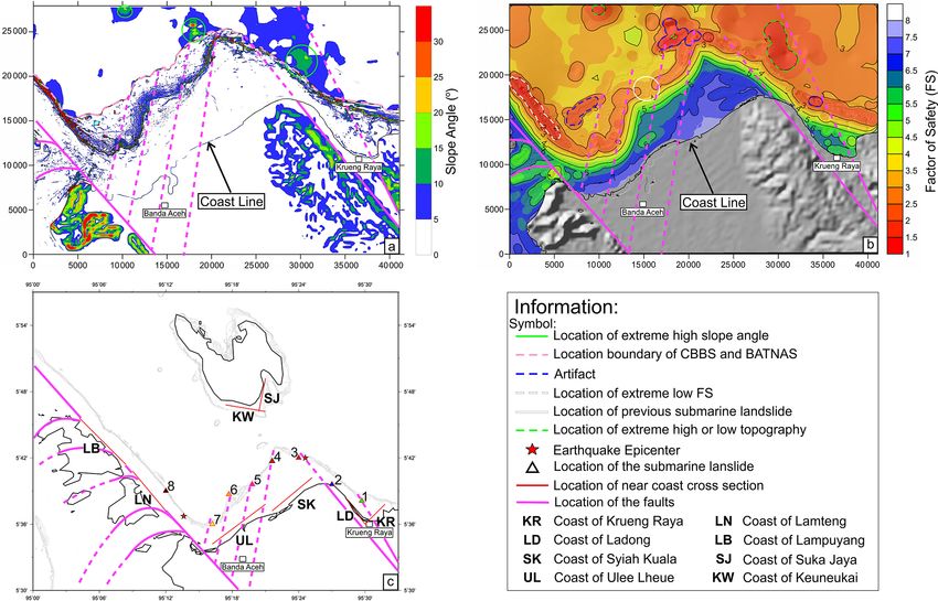
H. A. Haridhi et al.: Tsunami scenario triggered by submarine landslide offshore                                                       513

Table 1. Slope stability analysis parameters.

                                                         Topography resolution (m)
                                  Horizontal                      Minimum                           Maximum
                                     20                            −907                               566
                                                            Subsurface condition
                     Material            Groundwater     Earthquake
                     properties          configuration    loading                       Material properties
                                                                                           Angle of
                     Homogeneous               None         0.14       Cohesion       internal friction (◦ )     Weight
                                                                         0 kPa                 26              17.5 kN m−3
                                                              Stability analysis
                               Limit-equilibrium method                                   Search method
                          Bishop’s simplified limit equilibrium                                Box

In this study, Manning’s relative roughness n was set to 0.02            on this seismic profile, the S2 fault has a positive flower
in accordance with the assumption that the continental shelf             structure, indicating fault activity (Fig. 2b). These observa-
sediments were primarily composed of mud and silt (Lee and               tions imply that a submarine landslide previously occurred
Edwards, 1986).                                                          in this area and could be triggered by a fault rupture. How-
                                                                         ever, the precise landslide site along the S1 and S2 faults is
                                                                         difficult to identify due to the low resolution of the obtained
4     Analysis and results                                               seafloor morphology data, as it is outside the height reso-
                                                                         lution CBBS bathymetric data coverage (Fig. 4). The low-
4.1    Evidence of paleo-landslides                                      resolution bathymetry data of the seismic survey area limited
                                                                         the identification of any evidence of scarp- or mound-type
As presented in Fig. 1b, the seismic reflection SUMII-33                 structures for the evaluation of possible submarine landslide
(Fig. 3) is a long profile located in the sea between Suma-              sites.
tra Island and Weh Island, and it is nearly perpendicular to
the extending fault traces of S1 and S2. In the western part of          4.2       Stability evaluation of seafloor morphology
SUMII-33, chaotic facies at 17.5–20 km along the profile are
clearly visible (Fig. 3b), and its location is at the northward          The CBBS shallow bathymetric map (Figs. 4 and 5) has the
extension of the four-shear fault zone, as identified by CBBS            highest-resolution seafloor morphology in comparison to any
bathymetry (Figs. 4 and 5). The thickness of this chaotic fa-            other available bathymetric data set for shallow water in this
cies is approximately 0.2 s two-way-time (TWT). If we as-                region. The average angles along the continental shelf, con-
sume that the seismic wave velocity of marine sediment is                tinental slope and abyssal plain calculated by Scoop3D are
approximately 2000 m s−1 , the thickness of this chaotic fa-             between 0 to 5◦ , 6 to 30◦ , and 0 to 15◦ , respectively (Fig. 6a).
cies is approximately 400 m. In the eastern part of SUMII-               The abyssal plain typically has a low slope angle; however,
33, large chaotic facies are observed (interpreted as mass               some areas of the plain have substantially larger slope an-
transport deposit (MTD) facies) and is marked by the yel-                gles of 10–30◦ , as calculated by Scoop3D (marked as green
low dashed line in Fig. 3c. Similar thin-layer chaotic facies            circles in Fig. 6a). These unusual high slope angles may cor-
are also observed on the near coastal line of the short seis-            respond to the location of topographic high or low points;
mic profile SUMII-32 (Figs. 1b and 2). The chaotic facies                these morphological features are either submarine mountain
are observed at the slope of the SUMII-32 profile and may                or deeper portions of the abyssal plain. However, these un-
be related to the downslope turbidity or gravity flow. A fan-            usual high slope angles were detected at regions of the plain
shaped sediment is clearly observable on the abyssal plain               with sparse data; thus, the slope angle results may be unreli-
near the continental slope edge and may indicate an exten-               able. More reliable slope analysis results were obtained from
sional regime of the back-arc basin (Fig. 2c). Some similar              regions within the CBBS survey area; only these results were
chaotic facies below these fan-shaped sediment sequences at              used in the following analysis.
a distance of 12 500 m and 2.4 s TWT are difficult to distin-               As presented in Figs. 4 and 5, two river mouths are the in-
guish because the reflector amplitudes are too low, limiting             put source of sediment along this continental shelf; they are
our capability to interpret the profile (Fig. 2c). Furthermore,          located on the Banda Aceh plain (see Figs. 4 and 5, text label:

https://doi.org/10.5194/nhess-23-507-2023                                             Nat. Hazards Earth Syst. Sci., 23, 507–523, 2023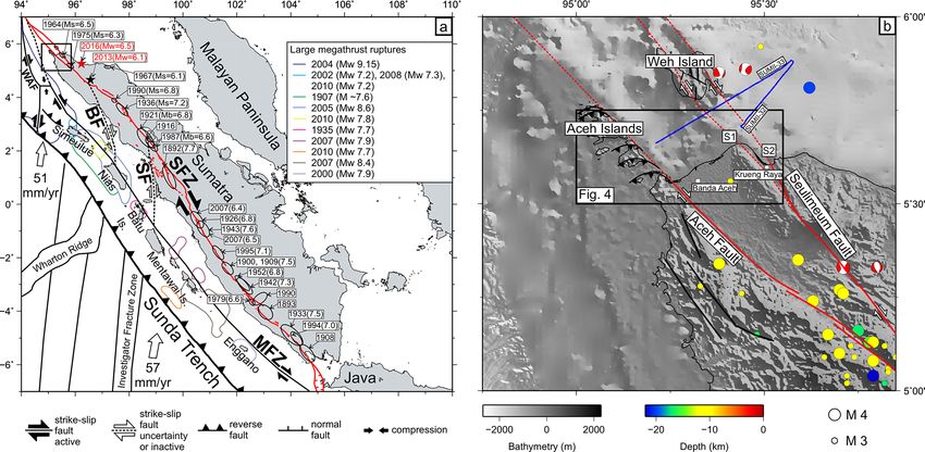
514 H. A. Haridhi et al.: Tsunami scenario triggered by submarine landslide offshore
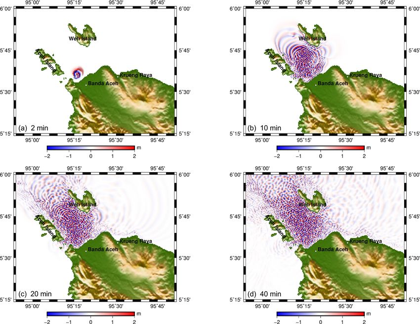
Figure 6. Regional slope distribution, slope stability analysis, location of the submarine landslide sources for the tsunami simulation scenarios
and the location of near-coast cross sections. (a) Map of slope angles. (b) FS from the slope stability analysis; red indicates higher likelihood
of failure. (c) Submarine landslide locations and their corresponding numbers; tsunami simulation scenarios are in Table 2.
Aceh and Lamnyong rivers). These thick sediments may pro- the continental slope along f3; this failure can be clearly ob-
vide support for extending the continental shelf. The shape of served in Fig. 5. This phenomenon further confirms our in-
the continental shelf is further modified by the activity of the terpretation of the chaotic facies in Fig. 2b.
shear faults (e.g., f1 to f4 in this area) below the shelf. The An area with a much lower FS value located at the conti-
spatial instability of the seafloor can be further evaluated us- nental slope east of Aceh Islands (marked as a white dashed
ing the FS index (Reid et al., 2015). Submarine landslides line in Fig. 6b) is also a reasonable landslide location for
may occur in regions with low FS values. The slope stabil- the tsunami simulation. However, this area is approximately
ity analysis results of Scoop3D are presented in Fig. 6b. Ar- 2.3 km east of the Aceh fault (the main SFZ segment), has a
eas with anomalously low FS values ≤ 2 are located at the nearby large river system as a sediment deposit source, and
continental slope offshore of Banda Aceh. The regions with no indication of chaotic facies on the seismic profile near to
low FS values and collocated with the four shear faults (f1 this location (Fig. 3); therefore, submarine landslides gener-
to f4) were identified as locations for further tsunami sim- ating tsunamis are unlikely to occur here despite the low FS
ulations (marked as locations 4 to 7 in Fig. 6c). The sedi- value at this location. However, this location was still used as
ment deposited above the area of the shear faults across the a submarine landslide source for the tsunami simulation (lo-
continental slope may increase the scale of landslides dur- cation 8 in Fig. 6c). These evaluated marine sites (locations 1
ing earthquake shaking. Two other sites with FS values and to 8 in Fig. 6c) are the possible locations of submarine land-
collocated with the faults (S1 and S2) were also identified as slides that are simulated in the tsunami scenarios described
possible submarine landslide locations, and they are marked in the following section.
as locations 1 and 3 in Fig. 6c. Another area with changes in
the FS value near the coast is located offshore north of Kru- 4.3 Tsunami model
eng Raya; the FS drastically changes from 4 to 2 within a
distance of 2 km. This location is also a submarine landslide
To simulate a tsunami with an earthquake source, we must
location for the tsunami simulation (location 2 in Fig. 6c).
first distinguish the earthquake sources using a fault model.
Figure 6b presents that the FS values along the continental
Genrich et al. (2000) suggested that the locking depth of
slope (marked by a solid white circle) are stable and high.
the Aceh and Seulimeum faults does not exceed 15 km. The
This location was identified as a previously failed section of
lengths of the Aceh and Seulimeum faults on land are up to
Nat. Hazards Earth Syst. Sci., 23, 507–523, 2023 https://doi.org/10.5194/nhess-23-507-2023
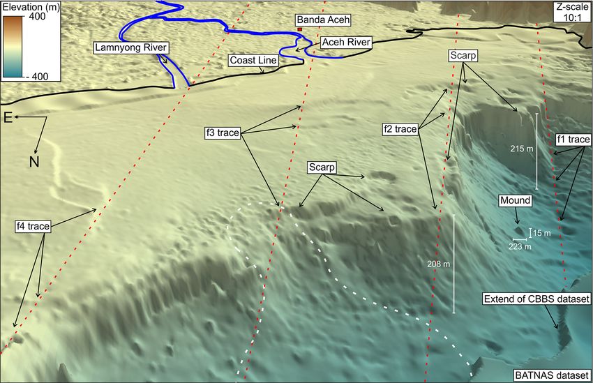
H. A. Haridhi et al.: Tsunami scenario triggered by submarine landslide offshore                                                  515

200 and 120 km, respectively (Sieh and Natawidjaja, 2000);
however, geophysical data are insufficient to reveal the de-
tails of their extensions to the northern offshore of Aceh.
McCaffrey (1992) suggested that an earthquake of Mw 7.5
or less is the largest possible event in the SFZ. The findings
of Sieh and Natawidjaja (2000), who summarized available
earthquake records, agree with this evaluation; accordingly,
the maximum magnitude of an earthquake event was set as
Mw 7 in this study. This earthquake could occur at any lo-
cation along the faults, but we chose an epicenter location
near the coast for our scenarios (star symbol in Fig. 6c).
The magnitude, RA, RL, RW, M0 , D and focal mechanism              Figure 7. Initial tsunami wave heights for the eight submarine land-
of the proposed earthquake are summarized in Table 2. The          slide scenarios with the X axis is towards offshore to the right.
earthquake focal mechanism in terms of the strike (θ ), dip
(δ) and slip (λ) were averaged from the Global CMT cat-
alog (http://www.globalcmt.org/, last access: 26 July 2022;        larity of the initial tsunami wave height compared with the
Dziewonski et al., 1981; Ekström et al., 2012).                    other scenarios (Fig. 7). These deviations could be due to the
   As presented in Fig. 6c and Table 2, two earthquakes were       landslide location with respect to other morphological fea-
considered in the tsunami simulation. COMCOT was used              tures, and the submarine landslide parameters were critical
to compute the tsunami wavefields induced by both strike–          for generating the initial tsunami wavefields.
slip earthquakes of Mw 7 in the studied region, and tsunami           After evaluation of all the simulated tsunami scenarios,
waves with an amplitude of 0.3–0.5 m were generated in the         scenarios 4 and 7 are included in the discussion (other sce-
entire coastal region. Thus, the tsunami hazard of a Mw 7          narios are presented in the Supplement). Figure 8 displays
strike–slip earthquake in this area (with epicentral distances     snapshots of simulated tsunami propagation for a submarine
less than 30 km) is correspond to the first degree of warn-        landslide at location 4 (Fig. 6c). The simulation reveals that
ing or on the alert level (Badan Metereologi Klimatologi           a continental slope landslide at this location can generate a
dan Geofisika, 2012). Therefore, earthquakes generate strong       tsunami as high as 4 m; at several sites of the coast, the maxi-
ground motion, which triggers submarine landslides, but the        mum amplitude of a tsunami wave can reach 8 m. These sites
tsunami hazard is due to the submarine landslide only. Typ-        are located southwest of Weh Island (KW, Fig. 6c) – the clos-
ically, tsunamis triggered by submarine landslides have run-       est coast to the landslide source. The propagation speed of
ups near the landslide location but have limited far-reaching      the computed tsunami is affected by the water depth. The
effects.                                                           time evolution of a tsunami wave between 10 and 40 min
   The size of paleo-submarine landslides below the northern       after the submarine landslide indicates higher speeds to the
waters offshore of Sumatra in the tsunami simulation was es-       north of the source (north offshore of Krueng Raya); how-
timated from seismic reflection data. The input parameters of      ever, the amplitude is lower than that of waves with a lower
COMCOT for submarine landslide sources were based on the           speed propagating in the west–southwest direction and ap-
collected information on regional active faults, the regional      proaching the north shore of Banda Aceh. The snapshots
maximum earthquake magnitude and the seafloor stability            in Fig. 8 also indicate that the frequency of tsunami waves
(Reid et al., 2015), and the parameters are listed in Table 2. A   changes when the wave front reaches the shallow water near
hypothetical submarine landslide with a length of 600 m and        the northern coast of Banda Aceh. The tsunami wave reaches
a width of 300 m (length–width ratio of 50 %) was consid-          the entire north coast of Aceh, west coast of Aceh Islands,
ered in this study. The COMCOT tsunami model indicated             and south coast of Weh Island in the first 10 min. The high-
that this submarine landslide with the aforementioned size         frequency wave is distributed throughout the shallow coastal
and ratio could generate a tsunami with a wave height com-         waters within 40 min.
parable to that in actual records, such as that of the recent         Images of the simulated tsunami wave from a submarine
Palu tsunami event studied by Gusman et al. (2019).                landslide at location 7 (Fig. 6c) are presented in Fig. 9. Sev-
   The computed spatial distribution of initial tsunami wave       eral islands surround the submarine landslide source. The
heights from eight submarine landslide sources (listed in Ta-      tsunami wavefields reveal that the maximum tsunami wave
ble 2) is presented in Fig. 7 computed along a perpendicular       high is approximately 2 m along the coast of Banda Aceh and
direction to the coast. All scenarios had depression waves         approximately 3.5 m along the southwestern coast of Weh Is-
toward shallow water, with subsidence ranging between 1.5          land. This landslide-generated tsunami wave is blocked and
and 8.5 m; leading elevated waves propagated toward deep           propagates with a low speed in the northwestern direction.
water, with rise ranging between 1.5 and 9 m. The largest          The propagation wavefield is unblocked in the northeastern
initial wave height was that in scenario 4, whereas the small-     direction, and the tsunami wave has a higher amplitude of
est was in scenario 1. However, scenario 3 had reversed po-        approximately 3.5 m in the southwestern coast of Weh Is-

https://doi.org/10.5194/nhess-23-507-2023                                    Nat. Hazards Earth Syst. Sci., 23, 507–523, 2023
516 H. A. Haridhi et al.: Tsunami scenario triggered by submarine landslide offshore
Table 2. COMCOT input parameter.
COMCOT parameter
Fault model (i.e., strike–slip earthquake Mw 7)
Epicenter Epicenter at
at Aceh Seulimeum
Depth (m) RL (m) RW (m) D (m) θ (◦ ) δ (◦ ) λ (◦ ) fault (◦ ) fault (◦ )
10 000 58 884.4 12 882.5 1.50 330 89 130 95.227◦ E 95.41◦ E
5.612◦ N 5.70◦ N
Submarine landslide scenario∗
Parameterrcase 1 2 3 4 5 6 7 8
c (◦ ) 95.49◦ E 95.45◦ E 95.40◦ E 95.36◦ E 95.33◦ E 95.295◦ E 95.27◦ E 95.20◦ E
5.65◦ N 5.66◦ N 5.70◦ N 5.695◦ N 5.66◦ N 5.645◦ N 5.6◦ N 5.65◦ N
l (m) 600 600 600 600 600 600 600 600
w (m) 300 300 300 300 300 300 300 300
h (m) 25 25 25 12.5 25 25 25 25
φ (◦ ) 10 4 10 8 5 7.5 7.5 30
∗ The submarine landslide locations (scenario number 1–8) are shown in Fig. 6c.
Figure 8. Snapshots of a tsunami wave from a submarine landslide source at location 4 of Fig. 6c at propagation times of (a) 2 min, (b) 10 min,
(c) 20 min and (d) 40 min.
land (KW, Fig. 6c) and approximately 2.5 m along the east- and hit the coasts of nearby islands. The computed maxi-
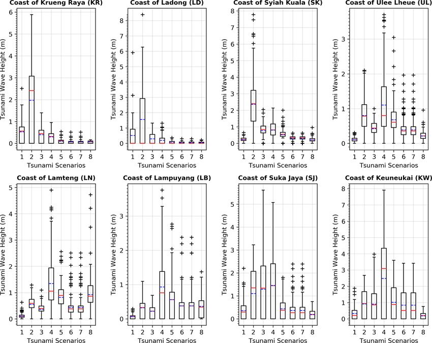
ern coast of Aceh Islands (LB and LN, Fig. 6c). Furthermore, mum tsunami wave amplitudes at eight coastal sites were ob-
the tsunami fully sweeps the northern coast of Banda Aceh tained for all submarine landslide scenarios (Fig. 6c). Statis-
and the surrounding islands within 10 min after the subma- tical analysis of the distribution of the tsunami wave height
rine landslide. at the eight selected sites is presented in Fig. 10 as a box-
The computed initial tsunami wavefields of all scenarios and-whisker plot (Massart et al., 2005). Landslide sources
(Fig. 7) reveal that the induced tsunami waves will extend located at the northeastern coast of Banda Aceh (i.e., scenar-
Nat. Hazards Earth Syst. Sci., 23, 507–523, 2023 https://doi.org/10.5194/nhess-23-507-2023H. A. Haridhi et al.: Tsunami scenario triggered by submarine landslide offshore 517
Figure 9. Snapshots of a tsunami wave from a submarine landslide source at location 7 of Fig. 6c at propagation times of (a) 2 min, (b) 10 min,
(c) 20 min and (d) 40 min.
ios 1 to 5) generate higher tsunami waves that hit the entire gions in the study area, and the contribution of the earthquake
northern coast of Aceh compared with tsunamis with sources to tsunami generation will resulted on first degree of warn-
located at the northwestern coast of Banda Aceh (i.e., sce- ing or on the alert level (Badan Metereologi Klimatologi dan
narios 6 to 8), which only affect the northern coast of Banda Geofisika, 2012). However, the source rupture of a strike–
Aceh, the eastern coast of Aceh Islands and the southwestern slip fault (Table 2) dominates the generation of ground mo-
coast of Weh Island. However, the tsunami wave generated tion through its horizonal components and its shaking of the
has nonsignificant effects on the eastern coast of Banda Aceh seafloor sediment. To verify the calculated ground motion in-
(Krueng Raya). The tsunami in scenario 4 had the greatest duced by the fault, we followed the evaluation procedure of
tsunami hazard of all analyzed scenarios. Phung et al. (2020) to predict ground motion by using four
global ground motion prediction equations (GMPEs), which
were developed for the global application as a part of the
5 Discussion NGA-West2 project: [ASK14], [BSSA14], [CB14], [CY14]
(Abrahamson et al., 2014; Boore et al., 2014; Campbell and
Tsunamis induced by giant megathrust earthquakes, such as Bozorgnia, 2014; Chiou and Youngs, 2014). The predicted
the 2004 Sumatra–Andaman earthquake or the 2011 Tohoku ground motion is presented in Fig. 11. The predicted ground
earthquake in Japan, and their mechanisms have been inves- acceleration is greater than 0.4 g for epicentral distances less
tigated (Araki et al., 2006; Liu and Zhao, 2018; Romano than 30 km. The eight landslide sites in Fig. 6c considered in
et al., 2014; Sibuet et al., 2007; Tsuji et al., 2011; Wang this paper are all 30 km from both simulated earthquakes, and
and Liu, 2006). These disastrous tsunamis were induced by the induced ground acceleration exceeds the pseudo-static
a significant co-seismic deformation due to sudden, vertical acceleration threshold (0.14 g) for triggering submarine land-
seafloor movement in the entire source area. Typically, earth- slides (Lee and Edwards, 1986).
quakes due to strike–slip fault movement are not associated According to computations conducted using the aforemen-
with significant uplift of the seafloor or with tsunami gener- tioned proposed global GMPE models, the predicted ground
ation. In this study, the tsunami wavefield from a strike–slip motion of a Mw 7 strike–slip fault can exceed the pseudo-
earthquake with source parameters listed in Table 2 was com- static acceleration threshold of 0.14 g for epicentral distances
puted. Consistent with previous reports, our results indicate greater than 70 km (Fig. 11). Thus, a Mw 7 earthquake oc-
that vertical seafloor movement is limited, and the induced curring on land may trigger a submarine landslide and may
tsunami wave is less than 0.5 m throughout the coastal re- induce a large tsunami. However, a submarine landslide-
https://doi.org/10.5194/nhess-23-507-2023 Nat. Hazards Earth Syst. Sci., 23, 507–523, 2023518 H. A. Haridhi et al.: Tsunami scenario triggered by submarine landslide offshore Figure 10. Box and whisker plots (Massart et al., 2005) of the maximum tsunami wave amplitude along the selected coastlines of Fig. 6c. The “+” sign indicates the extreme values, while the solid red and dashed blue lines indicate the median and mean, respectively. The title of each plot indicates the cross-section location, the x axis is shown for the landslide scenarios indicated in Table 2, while the y axis indicates the tsunami wave height shown in meters. induced tsunami can be triggered by nearby small-magnitude cations were not identified for either historical event. To cap- offshore events. Furthermore, multiple submarine landslides ture this uncertainty in possible source locations, two strike– can be triggered by one event at failure sites on the continen- slip earthquakes with a magnitude as high as that of these tal slope, enhancing tsunami hazards. The 2018 Palu earth- historical events were simulated in offshore areas, and eight quake is a real example of this phenomenon (Gusman et al., potential submarine landslide sites were considered in this 2019; Heidarzadeh et al., 2019). study (Fig. 6c). Numerous examples have been presented, indicating that To mitigate tsunami threats from landslide sources, numer- submarine landslides can be triggered by earthquakes. To ical modeling is a key method for both understanding the evaluate the submarine landslide-induced tsunami hazard, landslides and predicting landslide-induced tsunamis (Har- detailed examination of the occurrence of large earthquakes bitz et al., 2014; Masson et al., 2006). Modeling results indi- is necessary. Following the 2004 mega earthquake and cated that response times in the northern tip of the Suma- tsunami, the seismic activity in northern Sumatra was low tra are less than 10 min for all evaluated scenarios. Due (Fig. 1b). The absence of earthquakes in the northern SFZ to the mechanism discrepancies of submarine landslides, (i.e., at the Aceh and Seulimeum faults) indicates that this the established Indonesian Tsunami Early Warning System region is vulnerable to future earthquakes with a large mag- (INATEWS), which was constructed to provide warnings for nitude (McCloskey et al., 2005; Nalbant et al., 2005). Ac- tsunamis induced by earthquakes further away, has limited cording to historical reports, a large event in 1936 (Mw 7.1– capability to monitor submarine landslide-induced tsunamis. 7.3) (Newcomb and McCann, 1987; Sieh and Natawidjaja, Therefore, a new tsunami hazard mitigation and early warn- 2000) seriously damaged the city of Banda Aceh. Harbitz et ing system for tsunamis caused by landslides should be de- al. (2014) reported on historical tsunamis in Southeast Asia veloped; this is crucial due to the evidence for a large MTD and described a much older event close to northern Suma- deposit with a clear sequence exposed in the seismic section. tra. In 1837, this Mw 7.3 event caused substantial damage at Although the escape buildings constructed during the reha- Banda Aceh and moderate damage at more distant coastal ar- bilitation and reconstruction following the 2004 disaster and eas, such as Penang Island (Malaysia) and Teluk Ayer (Singa- some more of such building recently built by the government pore) (Harbitz et al., 2014; NCEI, 2019). However, source lo- (Syamsidik, personal communication, 26 October 2021) are Nat. Hazards Earth Syst. Sci., 23, 507–523, 2023 https://doi.org/10.5194/nhess-23-507-2023
H. A. Haridhi et al.: Tsunami scenario triggered by submarine landslide offshore                                                   519

Figure 11. Median response spectra predicted by the global candidate GMPEs for vertical strike–slip earthquakes with VS30 = 310 m s−1 at
selected epicentral distances (RX ). Sa named as an abbreviation of spectral acceleration.

ready for use, these buildings are still insufficient to accom-       6   Conclusions
modate the need for settlements from damaged coastal ar-
eas. This lack of refuge is another issue that must be over-
come to successfully manage a submarine landslide tsunami             A scenario of a submarine landslide in the northern waters
event. One of the most crucial actions to reduce the signif-          offshore Sumatra triggered by a strike–slip fault system was
icant damage and victims is to enhance better preparedness            proposed. The strike–slip fault movement in the marine envi-
and awareness of tsunami disaster. Although on the north-             ronment was demonstrated to trigger a significant landslide
ern coast of Aceh the tsunami preparedness in Aceh is at a            on an unstable continental slope, inducing a tsunami; the ef-
good level (Syamsidik et al., 2021), it is important to enhance       fects were quantitatively evaluated. Evidence of a large MTD
the preparedness and awareness of a group community such              deposit was also observed in the northern offshore area. The
as schools, disabilities and others, while opportunities to en-       northern tip of Sumatra has a high tsunami risk. This type of
hance the involvement of local institutions could be increased        tsunami can be triggered by a Mw 7 earthquake occurring on
in the activities related to disaster risk reduction.                 land or by a nearby small-magnitude offshore event. Further-
   In this study, scenarios of submarine landslides triggered         more, multiple submarine landslides can be triggered by a
by a strike–slip fault earthquake, which would induce signifi-        single event, enhancing the tsunami hazard. Similar tectonic
cant landslide tsunamis, have been demonstrated and quanti-           and environmental situations can be observed in other re-
tatively evaluated. Similar tectonic and environmental situa-         gions around the world, and our identified scenarios may also
tions can be observed in other regions around the world, and          be relevant in these regions. According to all scenarios eval-
our identified scenarios may also be relevant in these regions.       uated in this study, near the coast, the warning time for the
However, the compounded tsunami and earthquake hazard                 landslide tsunami would be less than 10 min. The established
in this submarine strike–slip fault system is still largely ne-       Indonesian Tsunami Early Warning System constructed to
glected in standard seismic hazard assessments.                       provide warnings for far earthquake-induced tsunamis has
                                                                      limited capability to monitor submarine landslide–induced
                                                                      tsunamis. Further landslide tsunami hazard assessments and
                                                                      improvements in the early warning system in this area could
                                                                      be achieved by using the proposed scenarios in this study.

https://doi.org/10.5194/nhess-23-507-2023                                       Nat. Hazards Earth Syst. Sci., 23, 507–523, 2023
520 H. A. Haridhi et al.: Tsunami scenario triggered by submarine landslide offshore
Code availability. The COMCOT version 1.7 used in this re- and Smith, 1991). Thanks for the English edited by Wallace Aca-
search is currently not an open-source model but is available from demic Editing. Additionally, we sincerely thank the two anonymous
the corresponding author upon reasonable request. GMT 5.4 is reviewers and editor Maria Ana Baptista for their constructive sug-
available at https://github.com/GenericMappingTools/gmt/releases/ gestions that have significantly improved the quality of this paper.
tag/5.4.5 (last access: 26 July 2022). Scoop3D is available at
https://doi.org/10.3133/tm14A1.
Financial support. This research has been supported by the In-
stitute for Information Industry, Ministry of Science and Tech-
Data availability. The data used in this study could be requested nology, Taiwan (grant nos. MOST 108-2116-M-001-010-MY3,
from the corresponding authors. MOST 108-2116-M-001-010-MY3 and MOST 109-2119-M-001-
011). This study was also funded by the Ministry of Education
and Culture of the Republic of Indoneia under the Resaerch Cen-
Supplement. The supplement related to this article is available on- ter of Universitas Syiah Kuala within the H-Index Scheme (grant
line at: https://doi.org/10.5194/nhess-23-507-2023-supplement. no. 169/UN11/SPK/PNBP/2021).
Author contributions. HAH and BSH initiated the original idea and Review statement. This paper was edited by Maria Ana Baptista
conceptualized the research. FK, CSLee, CSLiu and AM performed and reviewed by two anonymous referees.
the processing and analysis on the single-channel seismic reflec-
tion data. HAH, CRW, SR, SP, IF and IS performed the process-
ing and analysis on the community-based bathymetric survey data.
HAH and VBP performed the slope stability analysis and ground References
motion prediction with input from BSH and WKL. HAH and IF
performed the tsunami modeling with input from TRW and BSH. Abrahamson, N. A., Silva, W. J., and Kamai, R.: Sum-
All co-authors contributed to the interpretation of the results and to mary of the ASK14 ground motion relation for ac-
the article writing led by HAH and BSH. tive crustal regions, Earthq. Spectra, 30, 1025–1055,
https://doi.org/10.1193/070913EQS198M, 2014.
Araki, E., Shinohara, M., Obana, K., Yamada, T., Kaneda, Y.,
Competing interests. The contact author has declared that none of Kanazawa, T., and Suyehiro, K.: Aftershock distribution of the
the authors has any competing interests. 26 December 2004 Sumatra-Andaman earthquake from ocean
bottom seismographic observation, Earth, Planets Sp., 58, 113–
119, https://doi.org/10.1186/bf03353367, 2006.
Disclaimer. Publisher’s note: Copernicus Publications remains Badan Metereologi Klimatologi dan Geofisika: Pedoman Pelayanan
neutral with regard to jurisdictional claims in published maps and Peringatan Dini Tsunami InaTEWS Edisi kedua, BMKG,
institutional affiliations. Jakarta, 158 pp., 2012.
Barber, A. J. and Milsom, J. S. (Eds): Sumatra: geology, resources
and tectonic evolution, Geological Society of London, Oxford,
Acknowledgements. The Body of Rehabilitation and Reconstruc- 1–304, https://doi.org/10.1144/GSL.MEM.2005.031, 2005.
tion Nanggroe Aceh Darussalam and Nias coordinated the CBBS Berglar, K., Gaedicke, C., Ladage, S., and Thöle, H.: The Mentawai
project with funding from the ADB (grant number 0002-INO Earth- forearc sliver off Sumatra: A model for a strike-slip du-
quake and Tsunami Emergency Support Project). Haekal A. Haridhi plex at a regional scale, Tectonophysics, 710–711, 225–231,
would like to thank the Taiwan International Graduate Program https://doi.org/10.1016/j.tecto.2016.09.014, 2017.
(TIGP), Academia Sinica and National Central University for spon- BIG: DEMNAS – Seamless Digital Elevation Model (DEM)
soring his Ph.D study. We thank Tedi Yudistira for his effort to dig- dan Batimetri Nasional, Badan Inf. Geospasial, https://tanahair.
itize the SUMI and SUMII single-channel seismic reflection data indonesia.go.id/demnas/#/ (last access: 26 July 2022), 2018.
and Ifremer for access to this dataset, allowing us to fully use the Bishop, A. W.: The use of the slip circle in the sta-
results. We thank Yu-Ting Kuo at the Institute of Earth Science, bility analysis of slopes, Geotechnique, 5, 7–17,
Academia Sinica and Danny Chan at the Institute of Geoscience, https://doi.org/10.1680/geot.1955.5.1.7, 1955.
National Taiwan Ocean University, for their assistance in producing Boore, D. M., Stewart, J. P., Seyhan, E., and Atkinson, G. M.: NGA-
some of the figures. We thank Syamsidik at the Tsunami and Dis- West2 equations for predicting PGA, PGV, and 5 % damped PSA
aster Mitigation Research Center, Universitas Syiah Kuala, for their for shallow crustal earthquakes, Earthq. Spectra, 30, 1057–1085,
support and discussion. We thank the Panglima Laot, fishermen of https://doi.org/10.1193/070113EQS184M, 2014.
Lhok Krueng Aceh, the CBBS team (A. Syukri, A. Bonar, P. Dwi, Campbell, K. W. and Bozorgnia, Y.: NGA-West2 ground motion
F. Arif, P. Safrizal, B. Nazaruddin, S. Anjar, U. Maria, M. Siska, model for the average horizontal components of PGA, PGV, and
N. Suraiya, D. Putra, M. Aris and Zariansyah) and the Network of 5 % damped linear acceleration response spectra, Earthq. Spec-
Aquaculture Centers in Asia-Pacific for their cooperation, efforts tra, 30, 1087–1114, https://doi.org/10.1193/062913EQS175M,
and support during the CBBS data collection. The Generic Map- 2014.
ping Tools software package was used to draw map figures (Wessel Chiou, B. S. J. and Youngs, R. R.: Update of the Chiou and
Youngs NGA model for the average horizontal component of
Nat. Hazards Earth Syst. Sci., 23, 507–523, 2023 https://doi.org/10.5194/nhess-23-507-2023H. A. Haridhi et al.: Tsunami scenario triggered by submarine landslide offshore 521 peak ground motion and response spectra, Earthq. Spectra, 30, Heidarzadeh, M. and Satake, K.: Source properties of the 1998 July 1117–1153, https://doi.org/10.1193/072813EQS219M, 2014. 17 Papua New Guinea tsunami based on tide gauge records, Geo- Dugan, B. and Flemings, P. B.: Fluid flow and stability of the US phys. J. Int., 202, 361–369, https://doi.org/10.1093/gji/ggv145, continental slope offshore New Jersey from the Pleistocene to the 2015. present, Geofluids, 2, 137–146, https://doi.org/10.1046/j.1468- Heidarzadeh, M., Harada, T., Satake, K., Ishibe, T., and Takagawa, 8123.2002.00032.x, 2002. T.: Tsunamis from strike-slip earthquakes in the Wharton Basin, Duncan, J. M.: State of the art: limit equilibrium and finite- northeast Indian Ocean: March 2016 Mw7.8 event and its rela- element analysis of slopes, J. Geotech. Eng., 122, 577– tionship with the April 2012 Mw 8.6 event, Geophys. J. Int., 211, 596, https://doi.org/10.1061/(asce)0733-9410(1996)122:7(577), 1601–1612, https://doi.org/10.1093/gji/ggx395, 2017. 1996. Heidarzadeh, M., Muhari, A., and Wijanarto, A. B.: Insights on the Dziewonski, A. M., Chou, T.-A., and Woodhouse, J. H.: Determi- Source of the 28 September 2018 Sulawesi Tsunami, Indonesia nation of earthquake source parameters from waveform data for Based on Spectral Analyses and Numerical Simulations, Pure studies of global and regional seismicity, J. Geophys. Res., 86, Appl. Geophys., 176, 25–43, https://doi.org/10.1007/s00024- 2825–2852, 1981. 018-2065-9, 2019. Ekström, G., Nettles, M., and Dziewonski, A. M.: The Heidarzadeh, M., Ishibe, T., Sandanbata, O., Muhari, A., and global CMT project 2004–2010: Centroid-moment Wijanarto, A. B.: Numerical modeling of the subaerial tensors, Phys. Earth Planet. Inter., 200–201, 1–9, landslide source of the 22 December 2018 Anak Kraka- https://doi.org/10.1016/j.pepi.2012.04.002, 2012. toa volcanic tsunami, Indonesia, Ocean Eng., 195, 106733, Fernández-Blanco, D., Philippon, M., and von Hagke, C.: https://doi.org/10.1016/j.oceaneng.2019.106733, 2020. Structure and kinematics of the Sumatran Fault System in Heinrich, P. H., Piatanesi, A., and Hébert, H.: Numerical modelling North Sumatra (Indonesia), Tectonophysics, 693, 453–464, of tsunami generation and propagation from submarine slumps: https://doi.org/10.1016/j.tecto.2016.04.050, 2016. The 1998 Papua New Guinea event, Geophys. J. Int., 145, 97– Gasperini, L., Zaniboni, F., Armigliato, A., Tinti, S., Pagnoni, 111, https://doi.org/10.1111/j.1365-246X.2001.00336.x, 2001. G., Sinan, M., Marco, Ö., and Francesca, L.: Tsunami po- Hornbach, M. J., Braudy, N., Briggs, R. W., Cormier, M. H., Davis, tential source in the eastern Sea of Marmara (NW Turkey), M. B., Diebold, J. B., Dieudonne, N., Douilly, R., Frohlich, along the North Anatolian Fault system, Landslides, (June), C., Gulick, S. P. S., Johnson, H. E., Mann, P., McHugh, C., https://doi.org/10.1007/s10346-022-01929-0, 2022. Ryan-Mishkin, K., Prentice, C. S., Seeber, L., Sorlien, C. C., Genrich, J. F., Bock, Y., McCaffrey, R., Prawirodirdjo, L., Steckler, M. S., Symithe, S. J., Taylor, F. W., and Temple- Stevens, C. W., Puntodewo, S. S. O., Subarya, C., and ton, J.: High tsunami frequency as a result of combined strike- Wdowinski, S.: Distribution of slip at the northern Suma- slip faulting and coastal landslides, Nat. Geosci., 3, 783–788, tra fault system, J. Geophys. Res., 105, 28327–28341, https://doi.org/10.1038/ngeo975, 2010. https://doi.org/10.1029/2000JB900158, 2000. Kawata, Y., Benson, B. C., Borrero, J. C., Borrero, J. L., Daoies, Ghosal, D., Singh, S. C., Chauhan, A. P. S., and Hananto, H. L., Lange, W. P., Imamura, F., Letz, H., Nott, J., and N. D.: New insights on the offshore extension of the Synolakis, C. E.: Tsunami in papua New Guinea was as in- Great Sumatran fault, NW Sumatra, from marine geophysi- tense as first thought, Eos (Washington DC), 80, 101–105, cal studies, Geochemistry, Geophys. Geosystems, 13, Q0AF06, https://doi.org/10.1029/99EO00065, 1999. https://doi.org/10.1029/2012GC004122, 2012. Lee, J. H. and Edwards, D.: Regional method to assess off- Gusman, A. R., Supendi, P., Nugraha, A. D., Power, W., Latief, shore slope stability, J. Geothechnical Eng., 112, 489–509, H., Sunendar, H., Widiyantoro, S., Daryono, Wiyono, S. H., doi:doi.org/10.1061/(ASCE)0733-9410(1986)112:5(489), 1986. Hakim, A., Muhari, A., Wang, X., Burbidge, D., Palgu- Liu, P. L.-F., Cho, Y.-S., Briggs, M. J., Kanoglu, U., nadi, K., Hamling, I., and Daryono, M. R.: Source model and Synolakis, C. E.: Runup of solitary waves on for the tsunami inside Palu Bay following the 2018 Palu a circular island, J. Fluid Mech., 302, 259–285, earthquake, Indonesia, Geophys. Res. Lett., 46, 8721–8730, https://doi.org/10.1017/S0022112095004095, 1995. https://doi.org/10.1029/2019gl082717, 2019. Liu, X. and Zhao, D.: Upper and lower plate controls on the Hampton, M. A., Lee, H. J., and Locat, J.: Submarine landslides, great 2011 Tohoku-oki earthquake, Sci. Adv., 4, eaat4396, Rev. Geophys., 34, 33–59, https://doi.org/10.1029/95RG03287, https://doi.org/10.1126/sciadv.aat4396, 2018. 1996. Malod, J. A. and Kemal, B. M.: The Sumatra margin: Hanks, T. C. and Kanamori, H.: A moment mag- oblique subduction and lateral displacement of the accre- nitude scale, J. Geophys. Res., 84, 2348–2350, tionary prism, Geol. Soc. London, Spec. Publ., 106, 19–28, https://doi.org/10.1029/JB084iB05p02348, 1979. https://doi.org/10.1144/GSL.SP.1996.106.01.03, 1996. Harbitz, C. B., Løvholt, F., and Bungum, H.: Submarine landslide Massart, D. L., Smeyers-Verbeke, J., Capron, X., and Schlesier, K.: tsunamis: How extreme and how likely?, Nat. Hazards, 72, 1341– Visual presentation of data by means of box plots, LC-GC Eur., 1374, https://doi.org/10.1007/s11069-013-0681-3, 2014. 18, 215–218, 2005. Haridhi, H. A., Nanda, M., Wilson, C. R., and Rizal, S.: Pre- Masson, D. G., Harbitz, C. B., Wynn, R. B., Pedersen, G., and liminary study of the sea surface temperature (SST) at fish- Løvholt, F.: Submarine landslides: processes, triggers and haz- ing ground locations based on the net deployment of traditional ard prediction, Philos. Trans. R. Soc. A, 364, 2009–2039, purse-seine boats in the northern waters of Aceh – A community- https://doi.org/10.1098/rsta.2006.1810, 2006. based data collection approach, Reg. Stud. Mar. Sci., 8, 114–121, https://doi.org/10.1016/j.rsma.2016.10.002, 2016. https://doi.org/10.5194/nhess-23-507-2023 Nat. Hazards Earth Syst. Sci., 23, 507–523, 2023
You can also read