Surgical Technique Resorb Pin and Plate System - Revolutionary technique for osteosynthesis
←
→
Page content transcription
If your browser does not render page correctly, please read the page content below

A Company of WoodWelding SA using BoneWelding ® Technology

    Surgical Technique
Resorb Pin and Plate System
   Revolutionary technique for osteosynthesis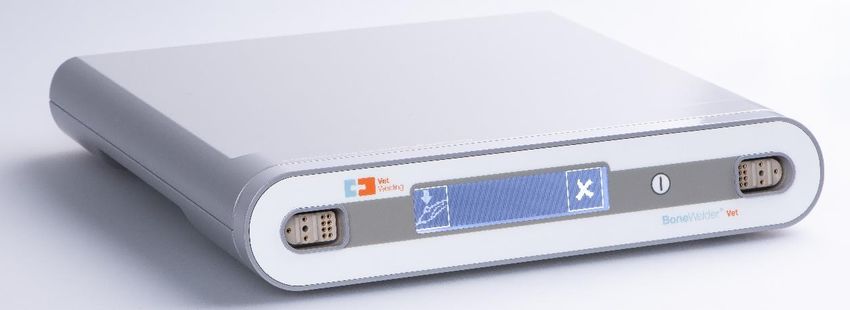

Resorb Pin and Plate System

Table of Contents
INTRODUCTION....................................................................................................................................... 2
INDICATIONS / CONTRAINDICATIONS ................................................................................................... 3
BoneWelding® EQUIPMENT .................................................................................................................... 4
RESORB PRODUCT RANGE .................................................................................................................... 7
SYSTEM DESCRIPTION ......................................................................................................................... 10
PREPARATION AND CLEANING ............................................................................................................ 12
SET-UP ................................................................................................................................................... 16
SURGICAL PROCEDURE ....................................................................................................................... 18
TROUBLESHOOTING ............................................................................................................................ 22

Nota Bene
The technique description herein is made available to the veterinary healthcare professional to illustrate the
authors’ suggested treatment for the uncomplicated procedure. In the final analysis, the preferred treatment
is that which addresses the needs of the specific patient. It is the responsibility of treating veterinary
physicians to determine and utilize the appropriate products and techniques according to their own clinical
judgment for each of their patients. Prior to performing this technique, please consult the Instructions for
Use documentation provided for each device for additional health and safety information.

                                                                            1
INTRODUCTION
BoneWelding® Fixation
The Resorb Pin and Plate System is a fully bioresorbable implant intended for surgical procedures in which
an internal fixation by resorbable implants is required for aligning, reconstructing, and stabilizing bone tissue.
The BoneWelding® technology employs ultrasonic energy to liquefy the polymeric components of the
resorbable pins at the interface with bone tissue. The liquid polymer flows into the marrow space of the
surrounding cancellous bone where it is immediately quenched and provides anchorage of the implant.

Resorb Pin and Plate System
The Resorb Pin and Plate System is a revolutionary technique for use in osteosynthesis. It combines highly
advanced ultrasound technology with resorbable implants to provide extremely stable fixation and
completely eliminate the need for a second operation.

The Resorb Pin and Plates are made of biocompatible and fully bioresorbable Polylactide (PDLLA). The “in-
vivo” degradation is based on the natural physiological process of hydrolysis, which results in a complete
metabolization of the polymer into H2O and CO2.

The procedure is simple: Resorb meshes or plates are warmed up, shaped to fit the application site and
then fixed in place with pins inserted into predrilled holes. This is done with a sonotrode that liquefies the
pins, thus causing them to bond with the meshes and penetrate into the bone cavities to anchor themselves
securely.

The Resorb pins are 2.1 mm in diameter and provided in lengths from 4 mm to 9 mm. The plates and meshes
are provided in a huge variety of different geometries, sizes and thicknesses that can be easily contoured
or cut with scissors intraoperatively. This ensures the right implant for every indication and easy adaption to
patient specific anatomy.

                                                       2
INDICATIONS / CONTRAINDICATIONS
Indications                                                 Contraindications
The Resorb Pin and Plate System is intended                 The veterinary surgeon’s education, training and
for surgical procedures in which an internal fixation       professional judgment must be relied upon to
by resorbable implants is required for aligning,            choose the most appropriate device and
reconstructing, and stabilizing bone tissue. It is          treatment.
indicated for use in non-load-bearing applications.
The Resorb pins are designed only to be inserted            Conditions presenting an increased risk of failure
with the BoneWelder® Vet system.                            include:
                                                             • The osteosynthesis material Resorb must not
Some of the many indications include:                            be used in areas exposed to mechanical
   • Osteosyntheses in non-load-bearing                          overload (e. g. fractures of the mandible).
       areas                                                     Otherwise, the Resorb pins, plates, and
   • Treatment of maxillofacial fractures                        meshes can break due to overstrain and
   • Laminoplasty                                                compromise the success of the treatment.
   • Reconstruction of bone defects after                    • Resorb plates and meshes cannot steadily
       cranial tumor resection                                   replace bone tissue. That is why they may not
   • Wound closure following equine tooth                        be used as permanent bone substitute
       extraction to prevent food contamination                  material. (i.e. use in applications containing a
   • Craniofacial corrective osteotomies                         large gap that will not bridge)
   • Neurosurgery                                            • Active or latent soft tissue and/or skin
                                                                 infections at the site of the operation.
    WARNING: Do not re-use or re-sterilize the               • Local inflammation of any origin at the repair
    implants! The re-use of the any implant (pin or              site.
    plate) is not possible. By being inserted with           • Hypersensitivity to foreign bodies.
    the BoneWelder® Vet equipment the implants               • Suspected material sensitivity or allergies
    liquefy and are firmly bonded with the                       and/or reactions to the implant materials
    cancellous bone. Implants, which have been                   used.
    taken from the sterile package and are not               • Autoimmune diseases.
    used for the procedure and the patient they              • Inadequate circulation or other pathological
    were intended for, must be discarded as they                 changes of the bone and/or soft tissue at the
    cannot be re-sterilized. The product shall only              repair site.
    be used by persons trained in the insertion              • A bad general state of health and/or vascular
    technique of the Resorb Pin and Plate system.                disorders and/or metabolic disorders (such
                                                                 as diabetes) that may affect healing.
                                                             • Bone tumors in the area of implant anchoring.
                                                             • Insufficient quantitative or qualitative hard
                                                                 and soft tissue.
                                                             • Concomitant diseases, e.g. degenerative
                                                                 disease processes with negative influence on
                                                                 successful healing.
                                                             • Osteoporosis or osteomalacia and other
                                                                 serious damage to the bone structure
                                                                 conflicting with solid anchoring of the implant
                                                                 components.
                                                             • Factors which may also impair the success of
                                                                 operations include:
                                                                  o Incorrect implantation technique.
                                                                  o Inadequate (too little, too short)
                                                                       postoperative load reduction and
                                                                       immobilization for healing.)

The Resorb Pin and Plates (polymer implants) are safe for use in magnetic resonance (MR) environments.

                                                        3
BoneWelding® EQUIPMENT
BoneWelder® Vet Ultrasonic Device and Handpiece
                                                                   The ultrasonic energy for the implantation of the
                                                                   Resorb Pin and Plates is provided by the
                                                                   BoneWelder® Vet ultrasound generator and
                                                                   applied via the attached handpiece.

Product Name                                                    Description.                      REF Nr.
BoneWelder® Vet System                                          Set                               01-00-001
Incl. Ultrasonic Device, Handpiece, Wrench and Power Cord

BoneWelder® Vet Ultrasonic Device                               Ultrasonic Device                 01-01-001

BoneWelder® Vet Handpiece                                       Instrument                        01-02-001

Wrench
                                                                BoneWelder® Vet Wrench
                                                                REF: 01-03-001

                                                                The wrench helps you to mount the sonotrode
                                                                properly on the handpiece making sure the
                                                                connection is tight for an appropriate transfer of
                                                                the ultrasonic energy into the implant.

Sonotrodes

BoneWelder® Vet                BoneWelder® Vet                  BoneWelder® Vet            BoneWelder® Vet
Standard Sonotrode,            Standard Sonotrode,              Smoothing Sonotrode,       Smoothing Sonotrode,
Straight                       Angled                           Straight                   angled
REF: V52-501-21-04             REF: V52-501-22-04               REF: V52-501-23-04         REF: V52-501-24-04
The standard sonotrode (handpiece tip) is                       The smoothing sonotrode (handpiece tip) is
mounted on the handpiece. It transmits the                      mounted on the handpiece. It transmits the
ultrasonic energy required to insert pins at either             ultrasonic energy to smooth implants.
angled or straight positions.

                                                            4
Drill Bit
    Ø 1.6 mm drill bit    Drill bit for pin lengths up to:            REF Nr.

                          4.0 mm                                      V52-616-04-07

                          5.0 mm                                      V52-616-05-07

                          9.0 mm                                      V52-616-10-07

                          The Ø 1.6 mm drill bit is sized specifically for the 2.1 mm pins and is offered in
                          lengths of 4,5 & 10 mm for use with the corresponding pins. It helps ensure
                          safe and easy handling of the implants and correct implantation.

Water Bath
                                                  The water bath can be used to warm the Resorb plates
                                                  just before use. After only a few seconds the implant can
                                                  be shaped, contoured, and cut. Allowing them to be
                                                  easily adapted to the surface of the bone segments.

                                                  Water Bath
                                                  (Incl. Thermal Unit, Cover Hood, Water Container and Power Cord)
                                                  REF: V52-400-10-04

Resorb Templates
The Various templates available can help to adapt the implants to the shape of the bone.

    Scale: 1/1                                             Scale: 1/1
    REF: V52-313-25-04                                     REF: V52-313-50-04
    Dimensions: 25 x 25 mm                                 Dimensions: 50 x 50 mm
    Titanium Template (Autoclavable)                       Titanium Template (Autoclavable)

                                                    5
Additional Instruments
The following instruments are not included but should be available in the operating room to aid in the
implantation of the Resorb Plates and Pin System:
    • Plate holding instrument: can be used to hold the plate in place during insertion of pins and assist
         in reducing the fracture.
    • Plate holding forceps: can be used to position and hold the plate in place until pins are inserted.
    • Scissors: can be used to cut a plate to the desired shape and size.

All components of the Resorb Pin and Plates System are developed and manufactured in cooperation with
specialized partners.

                                                   6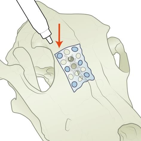
RESORB PRODUCT RANGE
Resorb Plates, Meshes and Sheets

             Scale: 1/1                   Scale: 1/1
             REF: V52-077-04-04           REF: V52-085-05-04
             Dimensions: 27 x 7 mm        Dimensions: 25 x 14 mm
             Thickness: 1 mm              Thickness: 1 mm

             Scale: 1/1
                                          Scale: 1/1
             REF: V52-076-22-04
                                          REF: V52-310-11-04
             Dimensions: 112 x 7 mm
                                          Dimensions: 11 x126 mm
             Thickness: 1 mm
                                          Thickness: 1 mm

                 Scale: 1/1
                 REF: V52-310-25-04
                 Dimensions: 26 x 26 mm
                 Thickness: 1.0 mm

                                      7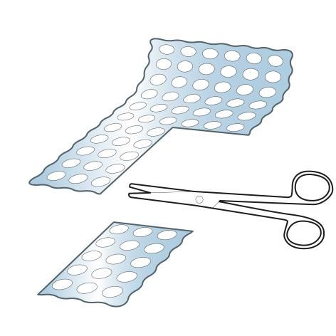
Scale: 1/1
                              REF: V52-310-50-04
                              Dimensions: 51 x 51 mm
                              Thickness: 1 mm

Scale: 1/1
REF: V52-311-15-04
Dimensions: 11 x 249 mm
Thickness: 1.5 mm

                              Scale: 1/1
                              REF: V52-306-52-04
                              Dimensions: 51 X 51 mm
                              Thickness: 0.6 mm

                          8
Scale: 1/1
REF: V52-310-13-04
Dimensions: 126 x126 mm
Thickness: 1 mm
Resorb Pins
2.1 mm Ø Pin Pin Length REF Nr. Quantity
4.0 mm V52-521-54-04 5
5.0 mm V52-521-55-04 5
7.0 mm
V52-521-57-04 5
9.0 mm
V52-521-59-04 5
9SYSTEM DESCRIPTION
BoneWelder® Vet
BoneWelder® Vet Ultrasonic Device Connecting cable (handpiece)
Connection sockets (2x) for handpiece Handpiece
Display Activation LED (blue)
Switch On/Standby Pushbutton handactivation
Power cord socket (IEC-C14) Sonotrode
Fuse socket Open-end wrench for sonotrodes
10Water Bath
Water container with frame Water bath on-off switch
Cover hood Orange thermo control “OK” light
Water bath thermal unit
11PREPARATION AND CLEANING
The warranty regarding handpiece cleaning and sterilization is limited to 250 reprocessing and sterilization
cycles. Once the maximum number of cycles has been reached, a corresponding message will be
displayed.
NOTICE
All components of the BoneWelder® Vet System are delivered non-sterile.
Preparation for Cleaning
• Remove visible contamination directly after use but latest within 2 hours after use.
• Remove sonotrode from the handpiece.
• Fully disconnect the BoneWelder® Vet from the power supply in all poles.
• Turn off and fully disconnect the water bath heating unit from the power supply in all poles.
• Disconnect the handpiece from the ultrasonic device.
• Brush down the handpiece with a soft nylon brush under running water until it appears visually
clean.
• Generally, use aldehyde-free, non-fixating cleaning and disinfection agents for manual as well as
machine cleaning and disinfection.
Cleaning / Disinfection
Sonotrode, Pre-Cleaning by Hand
• Rinse sonotrode under running water for 1 min (water temperature < 35°C (< 95°F)).
• Flush blind hole three times with 5 ml of water using a syringe and cannula attachment.
• Immerse sonotrode into a cleaning solution (e.g. 0.5% neodisher MediClean) for 10 min. Ensure
that the cleaning solution also enters the blind hole, and that the sonotrode does not come into
contact with other sonotrodes or instruments.
• Remove visible contamination using a soft plastic brush.
• Intensively clean the blind hole using a conical interdental brush.
• Then rinse the sonotrode again under running water for one minute and flush the blind hole three
times with 5 ml of water using a syringe and cannula attachment.
Sonotrode, by Machine
• After manual pre-cleaning, machine-clean and disinfect the sonotrode. Thermal disinfection is
carried out at 90°C (194°F) for 5 minutes (e.g. with cleaner neodisher MediClean).
• Store the sonotrode in a small tray basket during machine cleaning/disinfection.
The drying process is carried out at 125°C (257°F). If necessary, subsequent manual drying of the blind
hole is carried out using filtered, oil-free compressed air.
Handpiece, by Machine
• The handpiece of the BoneWelder® Vet is suitable for machine processing/thermal disinfection. It
can be processed with the same programs that have been released for surgical instruments and
implants. As regards to cleaning, be sure to follow the instructions provided by the manufacturer of
your washer disinfector(s) (W/D) as well as those provided by the manufacturers of the cleaners
and disinfectants used. The process (including loading) must guarantee sufficient removal of
residues.
• Only mildly alkaline cleaning agents are authorized for use.
• Coil the connecting cable with handpiece in a circle having a diameter of at least 20 cm.
• Arrange the handpiece so inside the washer disinfector that the sonotrode side of the handpiece
points downward. This prevents any accumulation of rinsing liquid in the handpiece.
12Handpiece, by Hand
Clean the handpiece with a clean, lint-free cloth moistened with a commercially available disinfectant
approved for use with instruments and based on ethanol (50/50) or isopropanol (70/30) (e.g. neodisher ®
MediClean by Dr. Weigert).
NOTICE
Risk of damage due to improper handling!
• The handpiece must not be immersed in a disinfecting or ultrasonic bath.
• Do not use any acetone-containing disinfectants for cleaning and disinfecting the handpiece.
Ultrasonic Device, by Hand
Clean the BoneWelder® Vet ultrasonic unit with a clean, lint-free cloth moistened with a commercially
available disinfectant approved for surface disinfection and based on ethanol or methanol (e.g. neoform
MED AF by Dr. Weigert).
WARNING
Danger of death by electric shock!
• Ingress of liquids into the device must be avoided under any circumstances!
• Before cleaning or disinfecting the BoneWelder® Vet, the device must be fully disconnected from
the power supply in all poles.
• Should moisture have penetrated into the device, dry it after disconnecting it from the supply.
Water Bath Device, by Hand
• All externally accessible parts of the heating unit can be cleaned with neutral, tenside based
cleaning agents (mild liquid detergents for manual use, neutral detergents).
• For wiping disinfection, neutral disinfectants (e.g. surface disinfectants) based on aldehydes,
quaternary ammonium compounds, etc., can be used.
• As regards surface cleaning and disinfection, follow the procedure recommended by the hygiene
board of your hospital or use another nationally recognized and approved method.
• Make sure that all disinfectant residues have been carefully removed before putting the device into
service.
WARNING
Danger of death by electric shock!
If liquid is inadvertently spilled over the heating plate of the heating unit or over the electrical connections,
there will be a risk of electric shock.
• Before cleaning or disinfecting the water bath, the device must be fully disconnected from the power
supply in all poles.
• Ingress of liquids into the water bath heating unit must be avoided under any circumstances! This
also applies when using sprays for cleaning and disinfection.
• Never pour liquid directly onto the heating plate of the heating unit.
• Should liquid happen to penetrate into the device (outside the water container), the water bath
must be withdrawn from service at once.
NOTICE
Risk of damage due to improper handling!
• Do not use any acetone-containing disinfectants for cleaning and disinfecting the water bath cover
or heating unit.
• Never use abrasives, disinfectants or solvents that could scratch the housing or damage the device
in any other way.
13Use of disinfectants containing alcohol
Be sure to observe the contact times, concentrations and application guidelines specified by the
manufacturer of the product.
To give you a guideline for the use of disinfectants, we have found after testing that the following substances
contained in the products in the concentrations shown below are safe.
The values indicated are maximum values and must not be exceeded!
• 96% ethanol = max. 40 g per 100 g disinfectant
• Propanol (propyl alcohol) = max. 35 g per 100 g disinfectant
• 25% glutaraldehyde = max. 75 mg per 100 g disinfectant
• Ethyl hexanol = max. 10 mg per 100 g disinfectant
• Formaldehyde solution = max. 10 mg per 100 g disinfectant
• Glyoxal = max. 165 mg per 100 g disinfectant
The safe use of products with a different composition is not warranted.
Be sure to observe the instructions provided by the manufacturers of both your washer disinfector(s) (W/D)
and the treatment agents used.
To prevent spotting, stains and other deposits or surface changes, we recommend using fully demineralized
water for the final rinse.
Water Bath Cover & Water Container, by Machine
The cover and the water container receptacle can be processed by machine with the same validated
programs used for anodized aluminum. The cover is heat-resistant and can thus be thermally disinfected by
machine.
To ensure the long-term service and performance of the water bath, careful maintenance is required.
Drill Bits, by Machine
We recommend a manual pre-cleaning with non-fixating cleaning and disinfecting detergents already at the
operating theatre.
Drills are suitable for machine processing/thermal disinfection. They can be processed with the same
programs that have been released for surgical instruments and implants. As regards cleaning, be sure to
follow the instructions provided by the manufacturer of your washer disinfector(s) (W/D) as well as those
provided by the manufacturers of the cleaners and disinfectants used. The process (including loading) must
guarantee sufficient removal of residues.
Sterilization
The following parts of the BoneWelder® Vet System are sterilizable:
• Handpiece
• Sonotrodes
• Wrench
• Water bath cover
• Water bath water container with white plastic frame
• Drill Bits
Improper sterilization and non-sterile handling can lead to serious health hazards for patients.
Sterilization must be carried out according to a validated steam sterilization process, for example in a
sterilizer complying with EN 285:2009 and ANSI/AAMI ST79, validated in accordance with ISO 17665
1:2006.
The fractionated (pulsing) vacuum method requires sterilization at 134°C (273°F)/2 bar with a minimum
holding time of 5 min.
14ANSI/AAMI ST79 recommends a minimum cycle time of 4 min at 132°C (270°F) for dynamic air removal
steam sterilization cycles. Please follow the instructions of the user manual of your steam sterilizer.
We recommend using a tray basket or, for small parts, a tray basket with cover.
For each use of the BoneWelder® Vet ultrasonic device a wrench, sonotrodes and handpiece in sterile
packaging is required.
NOTICE
Risk of damage due to improper handling!
• Do not sterilize the water bath heating unit, BoneWelder® Vet ultrasonic unit
Visual Check
• Check visually that all components used are free of defects.
• Damaged components must not be used and need to be replaced.
NOTICE
The tip of the sonotrode must not show any signs of mechanical damage. It must not be bent or rammed
(typical damage after the handpiece has fallen down).
15SET-UP
BoneWelder® Vet: Set-up Steps
1. Connect the connecting cable (7) of the handpiece (8) to the connecting socket (2) of the BoneWelder®
Vet ultrasonic device (1). The ultrasonic unit features 2 connecting sockets for handpieces (2).
2. Screw the sonotrode (11) manually in place on the handpiece and use the open-end wrench (12) to
ensure secure attachment (torque: max. 0.3 Nm).
3. Plug the power cord into the power cord socket (5) of the ultrasonic device and then into a mains
socket-outlet with ground contact. As soon as the unit has been connected to the power supply, it is
automatically set to standby mode. Therefore, full disconnection is possible only by pulling the plug of
the mains cable out of the socket-outlet.
4. Turning on the device with the On/Standby switch (4)
BoneWelder® Vet: Self-Test
CAUTION
Danger of burns!
If the sonotrode is allowed to make skin contact during the functional test, this can cause burns. Avoid
contact with skin, eyes, etc.!
5. The handpiece (if connected) is ready for a self-test indicated by:
a. the flashing activation LED (9) on the handpiece (8)
b. and the following symbol flashing on the corresponding side of the display (3):
6. The self-test for this handpiece will be started upon operating the hand activation pushbutton (10). The
message “Active” is shown on the display (3) and an acoustic signal appears. Hold down the
pushbutton (10) until the display (3) message changes from “Active” to “Cooling”, the checkmark
✓appears, the activation LED stops flashing and the acoustic signal changes.
NOTE: Be sure to keep the tip of the sonotrode out of contact with objects during this process. If the test is
successful, the device is automatically set to working mode.
BoneWelder® Vet: Ready
• Checkmark ✓ displayed (checkmark right or left, depending on which handpiece has been
tested): Means “no malfunction detected”.
• Generator-related error messages are displayed in text form, see section TOUBLESHOOTING.
16Water Bath: Set-up Steps
1. The water bath must be set up and operated in the sterile area of the operating environment. After
plugging the mains cable into the device and then into a mains socket-outlet with ground contact, the
water bath can be turned on with the on-off switch (16).
2. Then, cover the thermal unit (15) with the sterile cover hood (14). From this point, only sterile persons
are permitted to operate the device.
3. Place the sterile water container with the frame (13) into the sterile cover hood (14).
4. The water container can then be filled up with sterile fluid (e. g. aqua destilata, physiologic saline) until
the water level reaches the marking (approx. 500 ml).
5. The water bath is ready for action, when the orange thermo control display „OK“ (17) lights up.
Depending on the amount of liquid in the water container, heating time of the device is approx. 20
minutes.
NOTICE
Risk of damaging the implants!
Some of the sterile water bath liquid will evaporate during operation. To keep temperature variations as
low as possible, we recommend refilling in small quantities.
17SURGICAL PROCEDURE
Preoperative Planning
X-ray images or a CT scan should be used to identify fractures and plan reduction and implant choice.
Plate Selection
For fixation of the segments, plates and larger meshes can be
used, which can be cut to the required size with scissors if
necessary. The various implant types must be cut in soft
condition after having been warmed.
We recommend warming the implants in the prewarmed liquid of
the water bath just before they are used. After only a few
seconds the implant can be shaped, as a result of which it can
easily be adapted to the surface of the bone segment.
Fracture Reduction and Plate Contouring
First, the bone fragments need to be mobilized into their proper
position. Then the plate or mesh can be shaped to the bone with
one of the following two methods:
Option 1: A template for the chosen implant is placed across the
fracture area and bent to fit the bone surface. Then, the template
is removed from the patient. The appropriate Resorb plate is
preheated in the water bath. To ensure uniform heating of the
implant, use a pair of forceps to move the implant to and from in
the liquid. After only a few seconds the Resorb plate is formable
and can be adapted to the shape of the template.
Option 2: The Resorb plate or mesh is warmed in the preheated
water of the water bath. To ensure uniform heating of the
implant, use a pair of forceps to move the implant to and from in
the liquid. After only a few seconds the Resorb plate is formable
and can be shaped to the surface of the bone. This can be
performed either manually or directly on the patient’s bone if the
location permits.
18NOTICE
• Resorb implants can be reheated up to 3 times during the modeling process.
• Bending Resorb implants after they have cooled down can lead to fracture.
• Care must be taken that the plate holes to be used for fixation will not deform in the shaping process
• Implants should be heated up and shaped only immediately prior to use. It is not recommended to
leave the implant immersed in the water bath for an extended period of time.
Implant Placement
The material cools down quite fast and the implant keeps its
shape. The plate is then placed across the fracture area. It fits to
the bone surface perfectly.
Pre-Drilling
After proper placement of the plate according to the indication,
use the drill bit to create the pilot hole for the pin. The pin that is
closest to the fracture should be inserted first. The correct drill
depth is reached when the drill mechanically stops at the plate
surface, which is ensured by the integrated drill stop.
NOTICE
• It is important for the for the BoneWelding process that
the hole is drilled until the drill stop is reached.
• Surgeon is free to choose drill depth on a case by case
basis. However, drill depth should be at least the length
of the pin. If the pin is longer, either a shorter pin or a
longer drill may be used. Alternatively, pins can be cut
to desired length.
19Positioning and Implantation
1) The pin is removed from its packaging under aseptic
conditions and mounted onto the handpiece tip. The pin
holds onto the handpiece tip in the non-actuated state by
means of a taper joint. The implant should be pushed onto
the handpiece tip as far as the limit stop.
2) Seat the pin into the top of the pilot hole with slight pressure
(approx. 10 N).
3) Actuate the pushbutton on the handpiece and insert the pin
into the hole by light, manual axial pressure and concurrent
application of the ultrasonic energy.
4) Maintain the axial force during insertion and do not release
the pushbutton until the implant is fully advanced into the
bone and plate.
5) Stop the ultrasonic process (release the pushbutton) as soon
as the implant is successfully inserted (i.e. when it is flush with
the plate surface).
NOTICE
• The insertion process shall not take longer than 2-3 sec. between actuating and releasing the
pushbutton.
• The direction of the insertion has to exactly follow the pre-drilled hole.
Solidification
Immediately after insertion, the handpiece tip must be held in
place for a minimum of 3 seconds to allow the implant interface
to cool down and solidify. After solidification of the Resorb pin,
the handpiece tip can be removed from the pin with a light
twisting movement.
NOTICE
If a pin is not correctly inserted…
• An additional pin can be inserted in an adjacent hole.
• Or it may be replaced by drilling out the pin and inserting
a new pin in its place.
Insertion of Further Pins
Consecutive pins are inserted as before (following steps from
Predrilling to Solidification) until all pins have been inserted onto
the desired bone fragment. If fracture reduction is necessary, it
is recommended to start with the unstable bone fragment when
possible.
NOTICE
• It is recommended to insert at least 3 pins per fragment.
The more pins that are used the stronger the fixation.
20Reduction & Insertion of Pins into Remaining Bone Fragments
If the Resorb Pin and Plate system is being used to reconstruct
and stabilize a fracture, once all pins have been inserted into the
initial fragment, the fracture is once again reduced. Then pins
are inserted as before (following steps from Predrilling to
Solidification) into the remaining fragments until all desired pins
have been inserted.
If necessary, the plate contours can be smoothed using the
smoothing sonotrode.
Finally, after the plate is inserted successfully, the wound can be
closed.
Smoothing (Optional)
For smoothing the contours, the smoothing sonotrode may be
used as follows: Bring the sonotrode in contact with the plate,
press the activation switch until the material liquefies, release the
activation switch, and finally release the sonotrode.
Postoperative Treatment
Postoperative follow up, postoperative care and the duration of treatment depends on the patient’s
condition and are determined by the surgeon.
NOTICE
Implants are radiolucent and are not visible in x-ray or CT images.
21TROUBLESHOOTING
Display
Message displayed Cause Remedy
1. Power supply error Disconnect the unit from the
power supply, and then
2. Temperature meter defective
Generator error or fault. reconnect it.
3. Generator overtemperature
If the problem persists, return
4. Internal fault unit to manufacturer.
Acknowledge by pressing the
On/Standby switch.
Generator problem (during
Ultrasound trouble If the problem persists,
welding process).
disconnect the unit from the
supply.
Acknowledge by pressing the
1. Relieve pressure on System overload (sonotrode tip On/Standby switch, then clear
handpiece! stuck/jammed, excessive the handpiece problem and
2. Press On/Standby! pressure). operate the activation
pushbutton again
Maximum welding time of 60 s After a cooling-down time of 5 s,
Welding time
exceeded. the unit is ready for use again.
1. Tighten sonotrode! Tighten sonotrode with wrench
Sonotrode seated too loosely.
2. Press On/Standby! and acknowledge error.
Disconnect the unit from the
power supply, and then
Monitoring of all important reconnect it.
Internal fault
program modules.
If the problem persists, return
unit to manufacturer.
22Handpiece Statuses
Message displayed Cause Remedy
x No handpiece connected. Connect handpiece.
Temperature values measured on
Replace handpiece.
handpiece not plausible.
Message disappears
automatically as soon as the
Max. temperature reached on
temperature drops below 70°C
handpiece.
(158°F). Alternative: Replace
handpiece.
The handpiece cycle counter pictogram Message disappears
appears during self-test. (240 ≤cycle automatically once the self-test
counterPotential Malfunctions
Trouble Cause Identification Remedy
This does not compromise
the proper functioning of the
“Screeching” noises
BoneWelder® Vet system.
heard during the self- Residual moisture
Noise will subside
test or during use of or condensate on Clearly audible.
automatically during normal
the BoneWelder® Vet the contact points.
use of the device. It may be
system.
helpful to use longer drying
times after sterilization.
Sonotrode tip will not
detach from Resorb
pins.
Bent or rammed
Visual check. Replace sonotrode tip.
sonotrode tip.
Resorb pins fails to
attach to sonotrode
tip.
Observe required cooling-
Pin is generally
down time. Rotate the
Ultrasound applied deformed, sonotrode
sonotrode axially (twist) to
Sonotrode tip sticks to too long. cannot be removed
break the connection, see
Resorb pins. residue-free.
section.
Bent sonotrode tip. Visual check. Replace sonotrode tip.
Replace the handpiece. A
Handpiece indicator defective indicator on the
does not light up LED life exceeded. Visual check. handpiece has no adverse
during activation. effect on ultrasound
application.
Connect the system to the
No power supply. Visual check. power supply and operate the
On/Standby switch.
Mains fuse
Display dark. Electrical test. Replace mains fuse.
defective.
Unit not switched Press On/Standby switch until
Visual check.
on. display lights up.
Sonotrode Insert pin in adjacent hole
Pin insertion activation stopped Or
Visual check
interrupted before insertion Drill out pin and insert new
complete pin
24VetWelding AG
Muehlebach 2
6362 Stansstad / NW
Switzerland
+41 (0) 41 530 70 99
info@vetwelding.com
www.vetwelding.com
z
A Company of WoodWeldingSA using BoneWelding®Technology
The BoneWelding®technology is covered by the intellectual property rights of and licensed from WoodWeldingSA, Switzerland
For trademark information please refer to www.vetwelding.com/about-us REF 99-04-002 – V00You can also read