Stinger Jib Arm USER GUIDE - Operational Instructions & Specifications
←
→
Page content transcription
If your browser does not render page correctly, please read the page content below

Stinger™ Jib Arm
                                USER GUIDE
                  Operational Instructions & Specifications

                           Stinger™ Jib Arm mounted on a Hybrid dolly

© 2002 Chapman/Leonard Studio Equipment, Inc.    Revision 7 - 7/2008
It is Chapman/Leonard’s goal to provide the best camera support equipment with
    exceptional Customer Service. Therefore, we are compiling this User Guide to aid in
              the reordering of Replacement Parts for your Leased Equipment.
                For any questions regarding this User Guide, please contact
                    Customer Service at 888-883-6559 or 818-764-6726.

                            Chapman/Leonard Certified Locations:
      MAIN OFFICE                                             Canada                                              UK and Europe
  12950 Raymer Street,                                8301 Eastlake Drive                                   Chapman Leonard Studio
North Hollywood, CA 91605                           Burnaby, British Columbia                                    Equipment, Ltd.
                                                       V5A 4W2 Canada                                                 Unit 5
                                                                                                            Kingley Park Station Road
     888-883-6559
                                                          866-848-2602                                         Kings Langley, Herts
    or 818-764-6726                                      or 604-299-0913                                       England WD4 8GW
   Fax: 818-764-6730                                    Fax: 604-299-0926
    or 818-764-4347                                                                                                01923 265 953

           Texas                                             Louisiana                                                 Florida
1901 E. 51st Street, Suite 38                  660 Distributors Row Suite C & D                                 9460 Delegates Drive
   Austin, Texas 78723                             Elmwood Business Park                                        Orlando, Florida 32837
                                                   New Orleans, LA 70123
      512-473-0084                                                                                                 888-337-8243
     or 888-758-4826                                       888-758-4826                                           or 407-851-3456
    Fax: 512-473-0042                                                                                            Fax: 407-855-1653

                Use a Qualified Operator. For Assistance Please call our 24 hour Customer Service at 1-888-883-6559.                            1
                        © 2002 No part of this manual may be reproduced or electronically transmitted without
                                the written permission of Chapman/Leonard Studio Equipment, Inc.                                   Revision 7 - 7/2008
CONTENTS

                                 3          Features of the Stinger Jib Arm

                                 5          Transporting

                                 7          Hybrid Adapter

                                 8          Hustler Adapter

                                 9          Hustler IV Adapter

                                 10         High Post Kit Adapter

                                 11         Pedolly Mount

                                 12         Overslung to Underslung Mode

                                 16         Adding/Removing the Glide Head

                                 17         Adding/Removing Arm Extensions

                                 22         Configurations

                                 25         Mounting Options

                                 26         Splice Retainer Bar

   2                  Use a Qualified Operator. For Assistance Please call our 24 hour Customer Service at 1-888-883-6559.

                             © 2002 No part of this manual may be reproduced or electronically transmitted without
Revision 7 - 7/2008                  the written permission of Chapman/Leonard Studio Equipment, Inc.
Features of the Stinger Jib Arm
                                                                   Item #12000

                                                                                           1 ft. Front Arm
          Rigid without the need for a Cabling System                                         Extension
                                                                                                                                  Glide Head
                                              2 ft. Front Arm Extension                                                           see page 16
                                                       see page 22

         Removable Slider Weight
         for Fine Tune Balancing

                     Leveling Rod                                                                                                  Mitchell Mount
                                                                                                                                     see page 13
                                                                                                               Compatible with
                                                                                                               Variety of Heads
                                                             Tilt Drag Control

                                                                  Pan Drag Control

              1 ft. Rear Arm
                Extension

                Cushioned Stop

5, 10, & 25 lbs. Contoured Weights
    Require Less Space During
             Movement

                    1” Nut Mount Adapter
                         see page 7

                     In this Example: Mounted on a Chapman Hybrid II Plus Camera Dolly
                                                    see page 25 for other Mounting Options

                         Use a Qualified Operator. For Assistance Please call our 24 hour Customer Service at 1-888-883-6559.                   3
                                 © 2002 No part of this manual may be reproduced or electronically transmitted without
                                         the written permission of Chapman/Leonard Studio Equipment, Inc.                         Revision 7 - 7/2008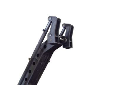
Features of the Stinger Jib Arm

          • Comes Assembled (In Full Configuration Upon Request) and Ready for Use Allowing Quick Setup
          or in its own special Cart for easy transport and storage in the smallest configuration of the arm.

          • Every Rental comes with all the parts for any configuration.

          • See Page 22 for all configurations of the Stinger Jib Arm.

          • Compact and Lightweight Arm.

          • Stinger Arm Glide System Allows up to 2 ft. of Horizontal Travel.

          • Black Anodized Arm for Easy Maintenance.

          • Works on Super PeeWee IV, Hustler and Hybrid Camera Dollies, along with a Variety of Bases.

          • Precision Design for Rigidity without the Need for Cabling System.

          • A Variety of Counter Balance Weights Available from 5 lbs. to 25 lbs.

          • Precision Design Weights are Contoured and Shaped on a Radius to Follow the Arc of the Arm.

          • Stinger Arm Glide System has Drag Control.

          • Cushioned Stops with Dampening Points at Top and Bottom Travel of the Arm.

          • Fluid Dampening System Resulting in Zero Backlash.

          • 360 Degree Continuous Pan Travel.

          • The Stinger Jib Arm has a Maximum Reach of 8 feet (from the Fulcrum).

          • Works with a Variety of Heads (including Remote Camera Systems).

          • Designed to Work within Tight Areas.

   4                         Use a Qualified Operator. For Assistance Please call our 24 hour Customer Service at 1-888-883-6559.

                                    © 2002 No part of this manual may be reproduced or electronically transmitted without
Revision 7 - 7/2008                         the written permission of Chapman/Leonard Studio Equipment, Inc.
Transporting the Stinger Jib Arm
Front Rear
For One Man Mounting and Assembly,
a Mobile Storage Case comes with every
Stinger Jib Arm. When in its case, there is
space below the stored Stinger Jib Arm that
enables rolling a dolly underneath.
A Mobile Weight Case with 425 lbs. of
Weights comes with every Stinger Jib Arm.
Each Arm comes with four 5 lbs. Weights,
two 10 lbs. Weights,
and seventeen 25 lbs. Weights.
Use a Qualified Operator. For Assistance Please call our 24 hour Customer Service at 1-888-883-6559. 5
© 2002 No part of this manual may be reproduced or electronically transmitted without
the written permission of Chapman/Leonard Studio Equipment, Inc. Revision 7 - 7/2008Transporting the Stinger Jib Arm
Mobile Storage Base for the Stinger Jib Arm
(without Mitchell Mount.)
For the Super PeeWee IV, Hustler IV and
Hybrid Series of dollies.
Mobile Storage Base for the Stinger Jib Arm Mobile Storage Base for the Stinger Jib Arm
when used with the Hybrid, Super PeeWee IV (with Mitchell Mount.) For use with Pedestals,
or Hustler dollies (with Universal Head.) HyHy, High Post Kits, and Hustler dollies without
Universal Head.
6 Use a Qualified Operator. For Assistance Please call our 24 hour Customer Service at 1-888-883-6559.
© 2002 No part of this manual may be reproduced or electronically transmitted without
Revision 7 - 7/2008 the written permission of Chapman/Leonard Studio Equipment, Inc.Hybrid Adapter for the Stinger Jib Arm
Standard Hybrid Mount setup with nose flipped.
Centering Nut.
Hybrid Adapter for the Stinger Jib Arm
installed and ready for the Stinger Jib Arm
to be mounted.
NOTE: The Legs MUST be set at 12 or 45
Degrees for Maximum Stability.
Hybrid with Stinger Jib Arm attached.
Mounting Nut.
Use a Qualified Operator. For Assistance Please call our 24 hour Customer Service at 1-888-883-6559. 7
© 2002 No part of this manual may be reproduced or electronically transmitted without
the written permission of Chapman/Leonard Studio Equipment, Inc. Revision 7 - 7/2008Hustler Adapter for the Stinger Jib Arm
Standard Mount for Hustler on Universal head.
Centering Nut.
Hustler Adapter for the Stinger Jib Arm
installed and ready for the Stinger Jib Arm
to be mounted.
Hustler with Stinger Jib Arm attached.
8 Use a Qualified Operator. For Assistance Please call our 24 hour Customer Service at 1-888-883-6559.
© 2002 No part of this manual may be reproduced or electronically transmitted without
Revision 7 - 7/2008 the written permission of Chapman/Leonard Studio Equipment, Inc.Hustler IV Adapter for the Stinger Jib Arm
Standard Hustler IV Mount setup.
Hustler IV Adapter for the Stinger Jib Arm
installed and ready for the Stinger Jib Arm
to be mounted.
Hustler IV with Stinger Jib Arm attached.
Use a Qualified Operator. For Assistance Please call our 24 hour Customer Service at 1-888-883-6559. 9
© 2002 No part of this manual may be reproduced or electronically transmitted without
the written permission of Chapman/Leonard Studio Equipment, Inc. Revision 7 - 7/2008High Post Adapter for the Stinger Jib Arm
Standard High Post Mount setup.
High Post Adapter installed and ready for the
Stinger Jib Arm to be mounted.
High Post with Stinger Jib Arm attached.
10 Use a Qualified Operator. For Assistance Please call our 24 hour Customer Service at 1-888-883-6559.
© 2002 No part of this manual may be reproduced or electronically transmitted without
Revision 7 - 7/2008 the written permission of Chapman/Leonard Studio Equipment, Inc.Pedolly Mount for the Stinger Jib Arm
The Pedolly with its column removed and a Center Post
Insert attached.
Before mounting the Stinger Jib Arm on the
Center Post Insert, all legs MUST be in the
45 degree configuration. This will provide
maximum stability for the base.
Use a rod or bar as leverage to tighten the
Castle Ring.
Use a Qualified Operator. For Assistance Please call our 24 hour Customer Service at 1-888-883-6559. 11
© 2002 No part of this manual may be reproduced or electronically transmitted without
the written permission of Chapman/Leonard Studio Equipment, Inc. Revision 7 - 7/2008Overslung to Underslung Mode
The Stinger Gliding Head in Overslung Mode.
Rubber Cover (viewed from below).
To change to the Underslung Mode, first remove
the Rubber Cover from the Gliding Head.
12 Use a Qualified Operator. For Assistance Please call our 24 hour Customer Service at 1-888-883-6559.
© 2002 No part of this manual may be reproduced or electronically transmitted without
Revision 7 - 7/2008 the written permission of Chapman/Leonard Studio Equipment, Inc.Overslung to Underslung Mode
Next remove the Locking Ring.
Separate the Mitchell Mount Head from the
Glider Mechanism.
The Mitchell Mount Head removed from the
Glider Mechanism.
Use a Qualified Operator. For Assistance Please call our 24 hour Customer Service at 1-888-883-6559. 13
© 2002 No part of this manual may be reproduced or electronically transmitted without
the written permission of Chapman/Leonard Studio Equipment, Inc. Revision 7 - 7/2008Overslung to Underslung Mode
Position the Mitchell Mount Head below the
Glider Mechanism.
Raise the Mitchell Mount Head until its threads
become visible above the Glider Mechanism.
Attach the Locking Ring to the Mitchell Mount
Head.
14 Use a Qualified Operator. For Assistance Please call our 24 hour Customer Service at 1-888-883-6559.
© 2002 No part of this manual may be reproduced or electronically transmitted without
Revision 7 - 7/2008 the written permission of Chapman/Leonard Studio Equipment, Inc.Overslung to Underslung Mode
Replace the Rubber Cover on the Glider
Mechanism.
The Underslung Mode of the Mitchell Mount
Head (viewed from below).
Use a Qualified Operator. For Assistance Please call our 24 hour Customer Service at 1-888-883-6559. 15
© 2002 No part of this manual may be reproduced or electronically transmitted without
the written permission of Chapman/Leonard Studio Equipment, Inc. Revision 7 - 7/2008Adding/Removing the Glide Head
Whenever extensions are added/removed from
the Stinger Jib Arm, the 2 ft. Glider should be
removed first. This will prevent the Glider from
falling to the ground when the Leveling Rods are
disconnected.
Loosen, but do not remove the retaining screw
on each side of the 2 ft. Glider.
The 2 ft. Glider can now be pulled from the arm.
16 Use a Qualified Operator. For Assistance Please call our 24 hour Customer Service at 1-888-883-6559.
© 2002 No part of this manual may be reproduced or electronically transmitted without
Revision 7 - 7/2008 the written permission of Chapman/Leonard Studio Equipment, Inc.Adding/Removing Arm Extensions
At this point, extensions of the Arm may be
safely added or removed.
The Weight Tray Knob (pictured below) for the
Weight Tray Rod may be stored on the Arm
(pictured at left) when weights are being added
or removed.
Before attempting to add or remove an arm
extension, remove all weights from the Tray.
Use a Qualified Operator. For Assistance Please call our 24 hour Customer Service at 1-888-883-6559. 17
© 2002 No part of this manual may be reproduced or electronically transmitted without
the written permission of Chapman/Leonard Studio Equipment, Inc. Revision 7 - 7/2008Adding/Removing Arm Extensions
Remove the Quick Release Pins from both sides
of the Leveling Rods.
Pull from both sides of each Leveling Rod.
Let the Nose hang from the Arm.
18 Use a Qualified Operator. For Assistance Please call our 24 hour Customer Service at 1-888-883-6559.
© 2002 No part of this manual may be reproduced or electronically transmitted without
Revision 7 - 7/2008 the written permission of Chapman/Leonard Studio Equipment, Inc.Adding/Removing Arm Extensions
Remove Leveling Rods on both sides of
the Arm.
Loosen both bolts on the first extension of the
arm. Do not remove the bolts from the arm.
The arm sections may be equipped with the
new cam activated splice. See page 26 for
an explanation of their setup.
With both bolts loosened, the Locking Plate
may be lifted enough to remove the Nose.
Use a Qualified Operator. For Assistance Please call our 24 hour Customer Service at 1-888-883-6559. 19
© 2002 No part of this manual may be reproduced or electronically transmitted without
the written permission of Chapman/Leonard Studio Equipment, Inc. Revision 7 - 7/2008Adding/Removing Arm Extensions
Lift the Locking Plate and slide the Nose off of
the arm.
As the nose is removed, support the arm until it
reaches its balance point.
Loosen both bolts on the first extension of the
arm. Do not remove the bolts from the arm.
Remove this section or add additional sections
to the arm.
20 Use a Qualified Operator. For Assistance Please call our 24 hour Customer Service at 1-888-883-6559.
© 2002 No part of this manual may be reproduced or electronically transmitted without
Revision 7 - 7/2008 the written permission of Chapman/Leonard Studio Equipment, Inc.Adding/Removing Arm Extensions
Replace the Nose on the end of the Arm.
Lift the Locking Plate to fully seat the Nose
section on the Arm.
Reattach the Leveling Rods on both sides of
the arm. The Arm is now ready for the Glider to
be reattached.
Use a Qualified Operator. For Assistance Please call our 24 hour Customer Service at 1-888-883-6559. 21
© 2002 No part of this manual may be reproduced or electronically transmitted without
the written permission of Chapman/Leonard Studio Equipment, Inc. Revision 7 - 7/2008Configurations
Stinger Configuration #1
2 Foot Glider
Item #12000
MH = 51.25”
MR = 5 feet
MP = 183.75 lbs.
BW = 57.5 lbs.
BAW = 187.5 lbs.
MOW = 738.75 lbs.
MOW w/ 100 lbs. Payload = 487.5 lbs. No Added Sections
BR = 2:1
UW = 130 lbs.
Stinger Configuration #2
2 Foot Glider
MH = 61.25”
MR = 6 feet
MP = 116 lbs.
BW = 105 lbs.
BAW = 242.5 lbs.
MOW = 667.5 lbs.
MOW w/ 100 lbs. Payload = 617.5 lbs. 1 Foot Section - Front
BR = 2.75:1
UW = 137.5 lbs.
Stinger Configuration #3
2 Foot Glider
MH = 71”
MR = 7 feet
MP = 75 lbs.
BW = 150 lbs.
BAW = 292 lbs.
MOW = 645 lbs.
BR = 3.5:1 2 Foot Section - Front
UW = 142 lbs.
MH = Maximum Height (From inverted camera Mitchell mount to base. Total height would be in addition to maximum
height of dolly arm.)
MR = Maximum Reach. (As measured from center post to camera Mitchell mount.)
MP = Maximum Payload.
BW = Bucket Weight for balanced arm. (No Payload.)
BAW = Balanced Arm Weight. (No Payload.)
MOW = Maximum Operating Weight of unit.
BR = Balance Ratio. (Determine the weight required in bucket to balance a Payload after arm has been balanced.)
UW = Unit Weight.
22 Use a Qualified Operator. For Assistance Please call our 24 hour Customer Service at 1-888-883-6559.
© 2002 No part of this manual may be reproduced or electronically transmitted without
Revision 7 - 7/2008 the written permission of Chapman/Leonard Studio Equipment, Inc.Configurations
Stinger Configuration #4
MH = 51.25” Item #12000
MR = 5 feet (60”)
MP = 367 lbs. 2 Foot Glider
BW = 10 lbs.
BAW = 147.5 lbs.
MOW = 929.5 lbs.
MOW w/ 100 lbs. Payload = 360.5 lbs. 1 Foot Section - Rear
BR = 1.13:1
UW = 137.5 lbs.
Stinger Configuration #5
MH = 61.25”
MR = 6 feet (72”)
MP = 246 lbs. 2 Foot Glider
BW = 37.5 lbs.
BAW = 183 lbs. 1 Foot Section - Front and
MOW = 815 lbs.
MOW w/ 100 lbs. Payload = 440 lbs. 1 Foot Section - Rear
BR = 1.57:1
UW = 145.5 lbs.
Stinger Configuration #6
MH = 70.75”
MR = 7 feet (84”)
MP = 181 lbs. 2 Foot Glider
BW = 62.5 lbs.
BAW = 212.5 lbs.
MOW = 756 lbs. 2 Foot Section - Front and
MOW w/ 100 lbs. Payload = 512.5 lbs. 1 Foot Section - Rear
BR = 2:1
UW = 150 lbs.
MH = Maximum Height (From inverted camera Mitchell mount to base. Total height would be in addition to maximum
height of dolly arm.)
MR = Maximum Reach. (As measured from center post to camera Mitchell mount.)
MP = Maximum Payload.
BW = Bucket Weight for balanced arm. (No Payload.)
BAW = Balanced Arm Weight. (No Payload.)
MOW = Maximum Operating Weight of unit.
BR = Balance Ratio. (Determine the weight required in bucket to balance a Payload after arm has been balanced.)
UW = Unit Weight.
Use a Qualified Operator. For Assistance Please call our 24 hour Customer Service at 1-888-883-6559. 23
© 2002 No part of this manual may be reproduced or electronically transmitted without
the written permission of Chapman/Leonard Studio Equipment, Inc. Revision 7 - 7/2008Configurations
Stinger Configuration #7
Item #12000
MH = 82.25”
MR = 8 feet (96”)
MP = 133 lbs. 2 Foot Glider
BW = 100 lbs.
BAW = 258 lbs.
2 Foot Section - Front plus
MOW = 716 lbs.
MOW w/ 100 lbs. Payload = 602 lbs. 1 Foot Section Front and
BR = 2.44:1 1 Foot Section - Rear
UW = 158 lbs.
For Configurations not shown in this brochure, or questions regarding a
special setup, Please contact a Chapman/Leonard Service Representative.
The reach of the Stinger Jib Arm offers an incredible
range of movement.
MH = Maximum Height (From inverted camera Mitchell mount to base. Total height would be in addition to maximum height
of dolly arm.)
MR = Maximum Reach. (As measured from center post to camera Mitchell mount.)
MP = Maximum Payload.
BW = Bucket Weight for balanced arm. (No Payload.)
BAW = Balanced Arm Weight. (No Payload.)
MOW = Maximum Operating Weight of unit.
BR = Balance Ratio. (Determine the weight required in bucket to balance a Payload after arm has been balanced.)
UW = Unit Weight.
24 Use a Qualified Operator. For Assistance Please call our 24 hour Customer Service at 1-888-883-6559.
© 2002 No part of this manual may be reproduced or electronically transmitted without
Revision 7 - 7/2008 the written permission of Chapman/Leonard Studio Equipment, Inc.The Stinger can be mounted on these Chapman/Leonard products:
41" 41" 40" 591/2" 461/2"
(1.4 m) (1.4 m) (1.4 m) (1.5 m) (1.6 m)
LenCin ® Pedolly ® PeeWee® Super PeeWee ® IV Hybrid
(With Center Post Insert) (With Center Post Insert) (With High Post Kit) (With High Post Kit)
MAXIMUM PAYLOAD = MAXIMUM PAYLOAD = MAXIMUM PAYLOAD = MAXIMUM PAYLOAD = MAXIMUM PAYLOAD =
1,100 lb. (499 kg) 1,100 lb. (499 kg) 1,100 lb. (499 kg) 350 lb. (159 kg) 1,900 lb. (862 kg)
Operating Weight of Unit = Operating Weight of Unit = Operating Weight of Unit = Operating Weight of Unit = Operating Weight of Unit =
245 lb. (111 kg) 305 lb. (139 kg) 386 lb. (175 kg) 391 lb. (178 kg) 501 lb. (227 kg)
Minimum Carrying Weight Minimum Carrying Weight Minimum Carrying Weight Minimum Carrying Weight Minimum Carrying Weight
of Unit = 164 lb. ( 75 kg) of Unit = 224 lb. (102 kg) of Unit = 280 lb. (127 kg) of Unit = 295 lb. (134 kg) of Unit = 395 lb. (179 kg)
+49" 54" 54"
(1.25 m) (1.5m) (1.5m)
Hy Hy ® Hustler Hustler IV
(With 7.5" Riser)
MAXIMUM PAYLOAD = MAXIMUM PAYLOAD = MAXIMUM PAYLOAD =
2,900 lb. (1,316 kg) 500 lb. (227 kg) 750 lb. (340 kg)
Operating Weight of Unit = Operating Weight of Unit = Operating Weight of Unit =
325 lb. (148 kg) 454 lb. (206 kg) 505 lb. (229 kg)
Minimum Carrying Weight Minimum Carrying Weight Minimum Carrying Weight
of Unit = 260 lb. (118 kg) of Unit = 420 lb. (191 kg) of Unit = 465 lb. (211 kg)
Virtually Maintenance Free Arm
• Wipe down the rollers each day.
Use a Qualified Operator. For Assistance Please call our 24 hour Customer Service at 1-888-883-6559. 25
© 2002 No part of this manual may be reproduced or electronically transmitted without
the written permission of Chapman/Leonard Studio Equipment, Inc. Revision 7 - 7/2008The Splice Retainer Bar with Cam Lock
ensures a tight fit between sections of the arm.
This is essential to maintaining the rigidity and stability of the Stinger Jib Arm while in operation.
Warning! Before adding or removing any section of the Stinger Jib Arm, the front Glider Section
MUST first be removed to avoid damaging the arm.
1 2
When attaching an arm section, loosen the Socket Head Push down on the Splice Retainer Bar until it is flush
Cap Screws enough to lift the Splice Retainer Bar over the against the arm section. The Screw Cam Lock may have to
Screw Cam Lock. be turned slightly to allow the Splice Retainer Bar to fit
properly against the arm.
3 4
Tighten the Socket Head Cap Screws, then loosen both Next, tighten the Screw Cam Lock to draw the arm sections
Socket Head Cap Screws one full turn. This is enough to together. Less than half a turn of the Screw Cam Lock is
allow the fit between the arm sections to be adjusted. necessary.
5 6
As shown above, the visible gap between the arm sections The final step is to tighten both Socket Head Cap Screws.
has been eliminated. Excessive torque is not required.
Disassembling the Stinger Jib Arm sections is simply the reverse of the above procedure.
Warning! Before adding or removing any section of the Stinger Jib Arm, the front Glider Section
MUST first be removed to avoid damaging the arm.
26 Use a Qualified Operator. For Assistance Please call our 24 hour Customer Service at 1-888-883-6559.
© 2002 No part of this manual may be reproduced or electronically transmitted without
Revision 7 - 7/2008 the written permission of Chapman/Leonard Studio Equipment, Inc.You can also read