SmARTflight: An Environmentally-Aware Adaptive Real-Time Flight Management System - Schloss Dagstuhl
←
→
Page content transcription
If your browser does not render page correctly, please read the page content below
smARTflight: An Environmentally-Aware
Adaptive Real-Time Flight Management System
Anam Farrukh
Department of Computer Science, Boston University, MA, USA
afarrukh@bu.edu
Richard West
Department of Computer Science, Boston University, MA, USA
richwest@bu.edu

        Abstract
Multi-rotor drones require real-time sensor data processing and control to maintain flight stability,
which is made more challenging by external disturbances such as wind. In this paper we introduce
smartflight: an environmentally-aware adaptive real-time flight management system. smartflight
adapts the execution frequencies of flight control tasks according to timing and safety-critical
constraints, in response to transient fluctuations of a drone’s attitude. In contrast to current
state-of-the-art methods, smartflight’s criticality-aware scheduler reduces the latency to return to
a steady-state target attitude. The system also improves the overall control accuracy and lowers
the frequency of adjustments to motor speeds to conserve power. A comparative case-study with
a well-known autopilot shows that smartflight reduces unnecessary control loop executions under
stable conditions, while reducing response time latency by as much as 60% in a given axis of rotation
when subjected to a 15° step attitude disturbance.

2012 ACM Subject Classification Computer systems organization → Firmware

Keywords and phrases adaptive real-time systems, safety criticality, flight controller, multi-rotor
drones, environmental awareness

Digital Object Identifier 10.4230/LIPIcs.ECRTS.2020.24

Funding This work is supported in part by the National Science Foundation (NSF) under Grant
#1527050. Any opinions, findings and conclusions or recommendations expressed in this material
are those of the author(s) and do not necessarily reflect the views of the NSF.

    1    Introduction
Multi-rotor drones and copters are increasingly being used in cyber-physical applications
that require unmanned aerial vehicles (UAVs). Their growing popularity is largely attributed
to their flexibility, low costs, ability to hover, and ease of maneuverability. Robust hardware
designs complemented with agile software stacks make them prime candidates for use in
ground-breaking applications such as aerial photography [9, 23], remote package delivery [15],
territorial exploration and inspection [25], infrastructure mapping [17,19], search and rescue [4,
18], and many others. The vast array of promising use-cases requires UAVs to navigate
different environments, which pose significant challenges to flight stability. In turn, more
sophisticated flight management systems are needed to dynamically compensate for adverse
environmental conditions, such as wind disturbances.
    At the heart of all multi-rotor aerial vehicles lies the autopilot. It is a flight controller
firmware or software that combines sensor data processing with attitude 1 estimation and
rotor speed adjustments to maintain a target trajectory. Flight management on typical multi-

1
    Attitude refers to the 3D orientation of an object relative to the Earth’s stationary reference frame.
           © Anam Farrukh and Richard West;
           licensed under Creative Commons License CC-BY
32nd Euromicro Conference on Real-Time Systems (ECRTS 2020).
Editor: Marcus Völp; Article No. 24; pp. 24:1–24:22
                  Leibniz International Proceedings in Informatics
                  Schloss Dagstuhl – Leibniz-Zentrum für Informatik, Dagstuhl Publishing, Germany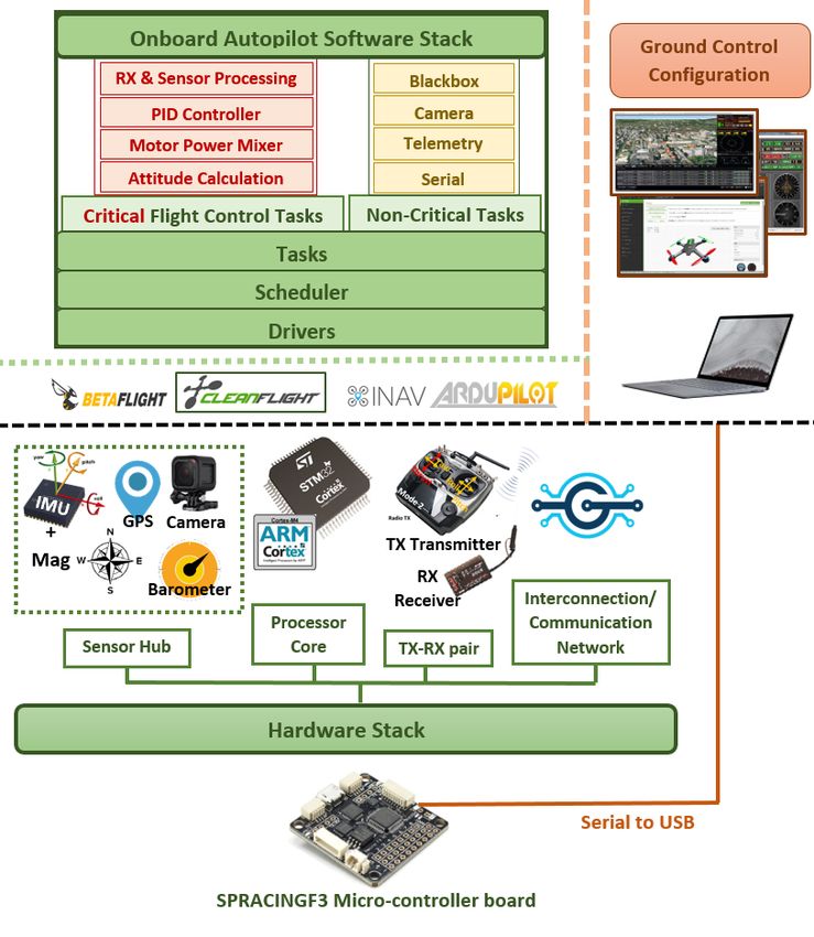
24:2 smARTflight
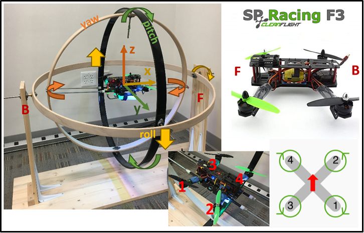
Figure 1 Hardware and software components of an autopilot firmware. Critical and
non-critical tasks are dispatched for execution by the underlying scheduler. Configuration applications
typically run on ground computers for initial setup of various parameters such as mission parameters,
loop times, PID gains, and filter cutoff frequencies.
rotor drones employs classical linear mechanisms that are energy inefficient, non-deterministic
in time, and prone to instability. Current autopilots lack the ability to dynamically adapt
flight behavior in response to external disturbances. Consequently varying environmental
conditions such as wind significantly impact the ability of a drone to maintain flight along a
target path. Manual intervention is oftentimes required to correct for situations that would
otherwise lead to crashes or inability to achieve flight objectives.
The key issues directly impacting drone performance include: 1) lack of adaptable and
timing predictable flight control, 2) inability to reactively restore stable flight in a precise
manner, 3) lack of low latency attitude recovery with fast response times, and 4) inefficient
usage of limited battery power. In light of these challenges, this paper presents smartflight:
an environmentally-aware, adaptive and real-time flight management system. smartflight
leverages sensor data processing and existing flight control functionality of the autopilot
to autonomously counteract adverse effects of environmental disturbances on the drone’s
attitude. This is achieved by smartly adapting the execution rates of critical flight controller
tasks, while guaranteeing their real-time and safety-critical scheduling constraints.
Current state-of-the-art autopilot systems combine safety-critical flight control function-
ality with non-safety-critical tasks such as camera data processing for on-screen displays
(OSDs), telemetry data transmission, and blackbox data logging onto a common hardware
platform. Fig. 1 characterizes an example software stack managed by a scheduler, along with
the essential hardware modules common to real-world copter autopilot architectures.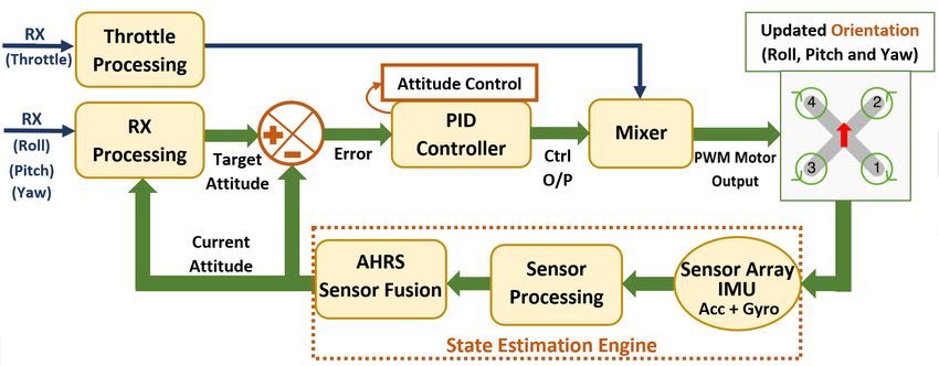
A. Farrukh and R. West                                                                                24:3

   Figure 2 Components of a flight control loop in an autopilot.

    The critical flight control tasks in charge of low-level attitude stabilization are often
tightly coupled within a closed loop. These tasks are the core constituents of the widely
used linear negative feedback control technique, depicted in Fig. 2. The loop involves high
frequency sampling for acquisition and processing of data from multiple sensors. It then
employs a series of filters and complex sensor fusion algorithms to estimate the current
orientation, or attitude of the drone, as part of the state estimation engine. This data is
compared with the target attitude received via the rx module, and the error is fed to the
PID (Proportional, Integral and Derivative) controller. The three regulators transform the
error between the actual and desired angular states into control signals for the electronic
speed controllers (ESCs). Controller output commands mixed with the input throttle data
are then used to adjust individual motor speeds and rotor rotations per minute (RPMs). This
compensates for actual versus desired maneuvers of the copter. A combination of differential
angular velocities results in an applied net torque about the center of gravity of the copter,
causing the system to undergo Euler angle rotations involving roll, pitch and yaw, with
respect to the Earth’s reference.
    To aid flight control, the system is equipped with: 1) a network of sensors (e.g. ac-
celerometers and gyroscopes collectively known as the Inertial Measurement Unit (IMU),
magnetometers, barometers, sonars, cameras, GPS and so forth), 2) a complete power
train with motors, rotor propellers and ESCs, and 3) a power distribution and regulation
sub-system.
    Collectively the entire system ensures stable and accurate flight control under steady-state
conditions. However as previously mentioned, current autopilot system designs are highly
sensitive to external changes in flight dynamics [11, 24] and thus fall short when subjected
to transient attitude disturbances. smartflight’s rate-adaptive, criticality-aware real-time
scheduling strategy overcomes the stability challenge by augmenting existing flight controllers
with enhanced environmental awareness. It improves flight stability and performance by
adopting a modular and structured approach to achieve deterministic, timing predictable
and adaptable flight control.
    The rate-adaptation policy is built upon a key insight that performance of a flight
controller is directly related to the rate of execution of its critical flight control loop [10].
When the drone experiences frequent changes in its orientation, a high frequency sampling
rate of the sensors captures the most recent data representing the state of the drone. This
allows the underlying PID controller to consequently correct for the current attitude error in
all three navigation dimensions, namely roll, pitch and yaw.
    The controller is therefore able to closely monitor the instantaneous forces acting on
the copter at any point in time. If the external forces on the copter vary significantly then
a correspondingly higher frequency of updates to the motor speeds leads to a much finer

                                                                                                    ECRTS 2020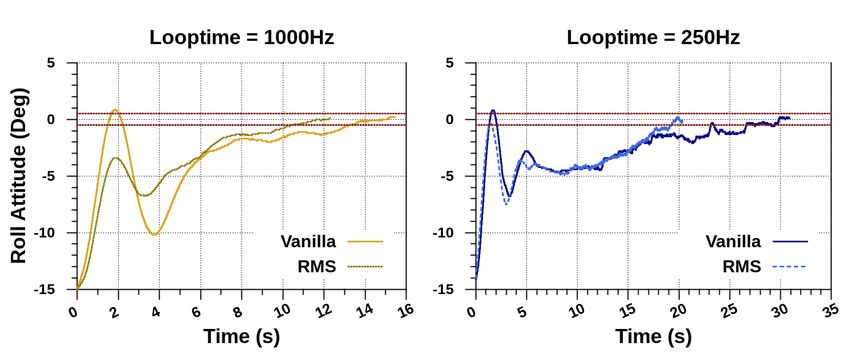
24:4   smARTflight

       granularity and accuracy of attitude corrections and control. Alternatively, infrequent sensor
       data processing and state estimation leads to inaccurate attitude predictions, resulting in
       potentially incorrect motor speed adjustments to maintain a target flight trajectory.
           In contrast, stable weather conditions impose little to no anomalous attitude variations,
       which presents an opportunity to reduce the rate of executions of the control loop. This
       allows efficient management of compute resources making them available for other non-
       critical mission-level functionality such as object detection and tracking [31], camera data
       processing for obstacle avoidance [12] and possible way-point navigation. Brushless DC
       motors responsible for generating the necessary lift force to maintain flight are connected
       directly to the main battery power and are the primary energy consumers on the drone. A
       reduction in the required updates to motor speeds therefore ensures energy efficient flight
       control.
           In summary, this paper does not focus on any specific flight control algorithm for
       multi-rotor UAVs, nor does it propose gain scheduling techniques for PID based controllers.
       Instead, we modify the rates of execution of existing control tasks with their default tuning
       parameters to enhance stability in the presence of disturbances. This work lays the foundation
       to empower autopilot software stacks with criticality-aware rate adaptation and real-time
       execution behavior.
           Our flight management framework: 1) identifies tasks as safety-critical and non-safety-
       critical within a well-known autopilot system, 2) identifies operating frequencies for individual
       tasks according to the system’s current criticality mode, 3) autonomously reasons about the
       varying external conditions to dynamically adapt task execution rates in a principled manner,
       4) ensures real-time management and accounting of processor cycles, and 5) guarantees
       hard-set execution time bounds for all flight controller tasks, to ensure flight success in the
       presence of timing uncertainties. smartflight compensates for instantaneous changes in the
       environment within predictable time bounds, ensuring low latency responsiveness to critical
       external events, preventing crashes and expediting recovery from anomalous attitude shifts.
       Compared to static-rate autopilots, the one adopted by smartflight avoids unnecessary
       control loop executions in comparatively stable weather conditions, to save battery power
       and free computational resources for additional tasks.
           The rest of the paper is organized as follows: Section 2 describes the background to
       the Cleanflight (CF) [7] flight control firmware used in this work. Included are the details
       of the vanilla scheduling policy and the resulting shortfalls of the state-of-art algorithm.
       Section 3 describes smartflight’s execution model, system and task criticality semantics
       and the mode-change policy. Section 4 details the experimental setup and evaluation of
       smartflight’s performance against the vanilla Cleanflight system. Finally Section 5 discusses
       related work and Section 6 concludes the paper.

        2     Background

       Autopilots. The open-source community of multi-rotor flight controllers features a rich
       set of projects tailored to either autonomous way-point navigation, such as Ardupilot [3],
       PX4 [22] and iNav [14] or first-person-view (FPV) drone racing such as Betaflight [5] and
       Cleanflight [7]. Despite their differences, the autopilots host more or less similar flight control
       logic as the standard feedback loop depicted in Fig. 2.
           smartflight works on the principle of general applicability across all autopilot firmwares
       by extending existing control logic with run-time adaptability of task execution rates. As
       an example implementation, we retrofit one of the most popular configurable autopilots,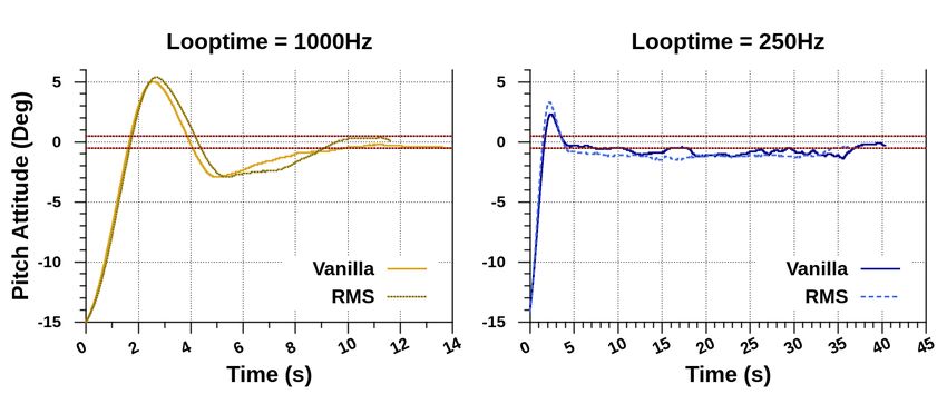
A. Farrukh and R. West                                                                                             24:5

Cleanflight (CF), with smartflight’s scheduling architecture. Designed specifically for
racing quadcopters, CF maintains a competitive edge over other popular open-source flight
controllers, in terms of flight efficiency, functional reliability and controller performance.
Combined with a functionally robust and minimalistic flight control stack it proves to be an
ideal autopilot platform to show smartflight’s performance benefits on cost-effective resource
constrained embedded hardware.
    Despite its advantages, Cleanflight is inflexible in the way it operates. Flight control
tasks are defined with static time periods that only act as soft time bounds. The underlying
scheduler is also based on a non-preemptive, best-effort scheduling policy. The lack of timing
predictability is one of the key contributors to variable task dispatch times, which often
manifests as a job starting earlier than expected or finishing later than required. Delay
variations between the release times of jobs for the same task become a major hindrance to
predictable adaptation within the system. The absence of strict timing constraints thus makes
task execution non-deterministic leading to a negative impact on the safety and robustness
of flight control. To avoid catastrophic failure under external disturbances, task times must
therefore be precisely controlled [13]. We verify this inherent uncertainty in task execution
times through real-world experiments with Vanilla CF as Phase-I of our evaluations (Section 4).
The next section provides a description of the Vanilla CF implementation.

2.1     Cleanflight Tasks

   Table 1 List of essential Cleanflight Tasks: (bold indicates critical tasks involved in low-level flight
control).

    Task Name         Time Period        Execution     Static       Criticality            Description
                        (µs)             Frequency   Priority       (smartflight)
                       Cleanflight/        (Hz)      (Vanilla CF)
                      smartflight (lo)
   task_system           100,000            10       Med-High           lo            Report system statistics
 task_bat_volt            20,000            50        Medium            lo             Sample battery voltage
                                                                                       Sample Gyroscope +
 task_gyropid         4,000 / 2,000      250 / 500   Real-Time          hi
                                                      (highest)                      PID-based motor control
    (Looptime)          / 1,000           / 1,000
   task_accel             1,000            1,000      Medium            hi          Sample Accelerometer data
 task_attitude           10,000            100        Medium            hi          Calculate current attitude
      task_rx             20,000            50          High            lo           Process receiver commands
                                                                                        Serial communication
   task_serial            10,000            100         Low             lo
                                                                                      with the ground computer

    Cleanflight (v.2.3.1) features 31 tasks in total, of which more than half constitute optional
add-on functionality. The critical flight control functionality is distributed over a set of 3
tasks: task_gyropid, task_accel and task_attitude. The core control loop (Fig. 2)
consists of: 1) a receiver task (task_rx) that processes reference inputs for the target
roll, pitch and yaw attitudes, 2) separate PID controllers for each axis of rotation that
adjust the output response based on the current attitude error (P gain), an accumulation
of past errors (I gain), and the rate of change in error (D gain), 3) a mixer component
that determines the magnitude of the thrust force applied to each motor, 4) several sensor
processing tasks (task_accel and task_gyropid), and 5) a quaternion-based Attitude
and Heading Reference Sub-system (AHRS: task_attitude) that combines sensor data
using Madgwick & Mahony’s complementary filter algorithm [29, 32] to compute the current
attitude of the copter.

                                                                                                                 ECRTS 2020
24:6 smARTflight
Throttle processing is incorporated within task_rx. A radio or ground control station
transmits commands wirelessly, which are then received by the hardware RX module on the
drone. task_rx varies in its importance to the overall flight control mechanism, depending
on the update frequency of target attitudes often dictated by the drone application. For our
experiments in Section 4, we consider task_rx a low importance and, hence, low-criticality
task since our target remains fixed throughout the flight of the drone. The essential tasks
are listed in Table 1 along with some low-criticality book-keeping functions. The table also
records static priorities and time periods that are used by the Vanilla CF scheduler
to determine task dispatch order at runtime.
We note that task_gyropid incorporates a chain of sub-tasks, enumerated earlier as item
points 2), 3) and 4) of the core control loop. This task sequentially samples gyroscope data,
executes the PID controller algorithm and updates motor output commands. task_gyropid
thus forms a fast loop that allows a user-configurable rate of execution known as the base
looptime in CF terminology. Looptime therefore represents the time period for one iteration
of the fast control loop. Other critical tasks in the main control loop, namely (task_accel
and task_attitude), work at non-configurable frequencies that are fixed integral multiples
of the base looptime.
2.2 Vanilla Scheduler
Algorithm 1 details Vanilla CF’s non-preemptive scheduling policy. The scheduler maintains
a fixed ready queue of tasks in decreasing order of static priorities from Table 1. Tasks
are scheduled from highest to lowest dynamic priority, which is calculated at run-time for
each task as a product of its static priority and the elapsed time since last execution (task
age-cycles) (Lines 6–7). The queue is traversed on every scheduler invocation and the task
with the highest dynamic priority is dispatched for execution according to Lines 9–11. The
chosen task either has a real-time static priority, or it has a lower static priority and has
aged for at least two consecutive time periods.
Algorithm 1 Vanilla Cleanflight scheduler.
Require: task parameters: lastExeT ime, staticP eriod, staticP rio
Require: rtTaskRunnable
1: procedure schedule
2: curT ime = get_time_micro()
3: selT ask = nil and selT askDynamicP rio = 0
4:
5: for all tasks in taskQueue do
6: update task → ageCycles = curT ime−task→lastExeT
task→staticP eriod
ime
7: calculate task → dynP rio = dynamic_prio(task)
8: /* Task with highest dynamic priority is selected */
9: if task → dynP rio > selT askDynamicP rio then
10: if task → staticP rio == Real-Time or
11: {!rtTaskRunnable and task → ageCycles > 1} then
12: selT ask = task
13: selT askDynamicP rio = task → dynP rio
14: end if
15: end if
16: end for
17: if selTask then
18: execute selected task function: selT ask → taskF unc()
19: Update task → lastExeT ime
20: Reset selT ask → ageCycles and selT ask → dynP rio
21: end if
22: end procedureA. Farrukh and R. West 24:7
We note that in Vanilla CF’s context “real-time” does not impose any temporal constraints
on a task but is used instead to represent the highest static priority. The dispatched task
runs to completion and only cooperatively yields control back to the scheduler at the end
of its execution. Depending on the execution time of a task, the time between consecutive
scheduler invocations may vary considerably.
3 smARTflight Execution Model
This section formalizes smartflight’s system and task model and details the execution
semantics.
Motivation
Higher execution rates offer finer granularity of control thereby reducing the convergence time
for a drone to asymptotically settle to its steady-state target attitude. With smartflight,
we are motivated to maximize the benefits associated with a high execution frequency of
the main flight control loop in adverse environmental conditions, while avoiding unnecessary
over-provisioning in comparatively calm conditions. smartflight therefore adapts individual
rates of all the critical flight control tasks in addition to the fast loop’s looptime. To this
end, we introduce an explicit notion of task and system safety criticality into Cleanflight. A
description of the real-time task and system model is presented next.
3.1 Task Model
The system is modeled as a set of real-time periodic tasks, {τ1 , τ2 , . . . , τn }, which are scheduled
according to an extension of the Liu & Layland model [6]. In oursystem, each task, τi ,
is parameterized by a 5-tuple {Ci , Ti (lo), Ti (hi) , Di (lo), Di (hi) , Li , pi (lo), pi (hi) },
with each term defined as follows:
Ci : worst-case computation time, or budget. The computational logic and structure of a
task remains unaltered. This implies that the execution time also remains more or less the
same across multiple job instances of the same task. Cleanflight is a closed system with a
fixed total number of tasks. We determine the run-time budget by profiling the system
online at every system start-up. This budget value is then used to calculate per task
utilization (Ui = C Ti ) which is then subsequently used to compute processor utilization
i
(Usys ).
Ci is computed pessimistically as a upper bound of the task’s actual computation time
by integrating all possible interrupt overheads that may be charged to the task’s runtime
budget due to I/O and memory requests, in addition to the scheduler overhead within
the base time.
T~i = Ti (lo), Ti (hi) : a vector of time periods. Each task τi has a corresponding period
Ti for each criticality level in the system, where Lsys = {lo, hi} is the set of system
criticality levels. Tasks explicitly modify their time periods across system mode changes.
System modes are discussed in Section 3.2. Each time period is a multiplicative inverse
of the corresponding task rate (Ri ) : Ti (Lsys ) = Ri (L1sys ) .
~ i = Di (lo), Di (hi) : a vector of deadlines. A job’s deadline is relative to its release
D
instance. Each deadline occurs Ti (Lsys ) time units after the job’s arrival time, implying
Di (Lsys ) = Ti (Lsys ).
Li = {lo, hi}: task criticality level. A task is assigned static criticality as described
in Table 1. In this paper, we consider only two task criticality levels. However, smartflight
is able to support more than two levels when finer-grained task rate adaptations are
ECRTS 202024:8 smARTflight
required across system mode changes, to compensate for environmental factors. This
would allow the system to exhibit a more graceful transitional response to varying
exogenous conditions.
p~i = pi (lo), pi (hi) : a vector of task priorities assigned under the Rate-Monotonic
priority assignment algorithm (RMS) [6]. Tasks with higher rates and, hence, shorter time
periods, are assigned higher priorities than tasks with longer periods. Tasks therefore
have different priorities in different system modes.
All Cleanflight tasks are modified to be preemptible in smartflight. Thus unlike Vanilla
CF, their execution is interleaved. We present our scheduling framework that supports this
task model in Section 3.3.
Task criticality (Li ) is defined as a measure of the task’s functional importance to the
overall flight control operation. hi criticality is associated with tasks that must operate
correctly within the real-time temporal bounds of their budget, Ci , and period, Ti , in order
to maintain stable flight and avoid crashing the drone. All flight-control tasks shown in bold
in Table 1 are assigned to this level. In contrast, tasks that have minimal impact to the
runtime flight control functionality are assigned a lo criticality. Examples of such tasks
include blackbox logging, camera data capture, and serial transmission.
Task criticality allows us to directly associate one of the two rate-adaptation behaviors,
rate increase (↑) or decrease (↓), with each task across the two system execution modes. A hi
criticality task’s frequency increases on a lo → hi mode transition of the system. Inversely,
a lo criticality task’s frequency decreases. This counteracts the increase in execution rate for
hi criticality tasks by acting as a protection mechanism against potential system overload
situations. However, smartflight optionally allows lo criticality tasks to retain their current
rate of execution on a lo → hi mode transition, if real-time task schedulability is maintained
according to the RMS utilization bound. Notwithstanding, all task rates are reset back
to the original lo mode values when the system transitions from hi → lo mode. Table 2
summarizes the relationship between task rates in terms of the time periods (Ti ) for both lo
and hi criticality tasks in each system mode.
Table 2 Relationship between task time periods (Ti ) for both lo and hi criticality tasks in each system
mode (Lsys ).
lo Criticality Tasks hi Criticality Tasks
Ti (Lsys = lo) ≤ Ti (Lsys = hi) Ti (Lsys = lo) > Ti (Lsys = hi)
3.2 System Model
For the purposes of this paper, the system is characterized by two distinct steady-state
execution modes, or system criticality levels, referred to as lo and hi. System criticality
captures the direct influence of external disturbances on the attitude of the drone. Each mode
is therefore defined in terms of the captured environmental dynamics and the corresponding
effects on the stability of flight.
On every iteration of the control loop, environmental data, as reported by the navigation
sensors, is sampled and processed to compute an updated value for the drone’s current
attitude in each axis of rotation: roll, pitch and yaw. The output of the state-estimation
engine is then used to trigger a particular system execution mode at millisecond granularity.
Each mode is activated as a complementary response to variation in attitude when compared
against the corresponding angular thresholds in all three dimensions. Since each axis isA. Farrukh and R. West 24:9
independently subjected to environmental influence, we identify three independent Euler
angle thresholds that represent upper bounds on the maximum tolerable deflection from
the copter’s target attitude along that axis. If the fluctuation goes beyond the maximum
bound in any one of the axes, the system switches to hi mode. The system reverts back to
lo mode only if the intensity of variations falls below the predefined threshold in all three
axes. This ensures low latency response times in all dimensions. A typical scenario is the
absence or presence of high winds that directly translates to calm (lo) versus adverse (hi)
environmental conditions.
The flight controller tasks are characterized by different execution rates, as a function
of system mode and individual task criticality. Tasks gracefully adapt their rates across
mode-switches as previously described in our task model. The system mode acts as a flag to
trigger an increase or decrease of the task execution rates, which in-turn ensures a timely
and adaptable flight control response to the changing environment. The system always starts
in lo mode, with subsequent lo → hi and hi → lo transitions occurring as a result of
environmental conditions.
Mode Transition Protocol
Mode change requests are modeled as asynchronous events within the system. These
are flagged in the control loop iteration following their arrival. smartflight’s version of
task_attitude registers the mode change request with minimal delay, by comparing angle
thresholds with current attitude values for each axis. The system is then able to react to
changing conditions with very low mode-switching delay, according to the following mode
transition definitions:
lo → hi: Transition begins with the arrival of the mode change event and ends when all
the hi criticality tasks have increased their rates of execution, or equivalently decreased
their time periods, from Ti|{Li =hi} (lo) to Ti|{Li =hi} (hi). The algorithm waits for every
hi criticality task to complete its lo mode execution before updating its time period,
thereby preserving the timing properties of the task across the system mode change.
This policy adopts a graceful transition of rates, thus maintaining task schedulability
in real-time. After every switch, the processor’s utilization (Usys ) is re-calculated and
compared against the maximum allowed utilization. On exceeding the bound, excess
utilization is compensated by decreasing the rates of execution, or equivalently increasing
the time periods, of all the lo criticality tasks from Ti|{Li =lo} (lo) to Ti|{Li =lo} (hi). This
is done in consecutive iterations until the updated taskset regains a feasible schedule.
Increasing a lo criticality task’s period only serves to raise the likelihood of regaining a
feasible schedule. Consequently, the time periods for lo criticality tasks are increased
without waiting for their prior lo mode executions to complete. The current job execution
is thus carried over from lo to hi mode without disruption.
hi → lo: Follows by symmetry of argument presented above.
Both system mode transitions are represented in algorithmic form in Algorithm 2. A
new mode change request is only serviced if the system is in either of the two steady-state
system modes. This ensures non-overlapping and graceful transitions between task rate
parameters. To avoid frequent oscillations between lo and hi states, consecutive mode
changes are temporally spaced out in an artificial manner. The amount of delay is configured
by the programmer as part of the system tuning process. We next discuss smartflight’s
adaptive real-time scheduling policy that replaces Cleanflight’s vanilla scheduler in our
example implementation.
ECRTS 202024:10 smARTflight
Algorithm 2 smartflight’s rate-adaptation policy.
Require: taskQueue[] with tasks arranged from high → low priority/rate
Require: current_task
Require: T _decrease and T _increase
RM S
Require: Ubound
1: if lo → hi then
2: if current_task → criticality == hi & current_task yielded then
3: Tihi (Lsys = hi) = Tihi (Lsys = lo) − T _decrease
4: Insert task in taskQueue[] at new position based on updated rate
5: Update task and system utilization: Uihi & Usys
6: end if
RM S
7: while Usys > Ubound do
8: for all lo tasks ∈ taskQueue[] do
9: Tilo (Lsys = hi) = Tilo (Lsys = lo) + T _increase
10: Update task utilization : Uilo
11: Update Usys (Lsys = hi)
12: end for
13: end while
14: else if hi → lo then
15: for all tasks ∈ taskQueue[] do
16: Restore Ti (lo) . mirrored logic from lo→hi
17: Insert task in taskQueue[] at old position
18: Update task utilization: Ui
19: end for
RM S
20: Recalculate Usys (Lsys = lo) and check against Ubound
21: end if
3.3 Rate-Adaptive Real-Time Scheduling Algorithm
smartflight extends Cleanflight’s task model with real-time constraints to ensure predictable
execution. In accordance with the task model presented in Section 3.1, each periodic task
(τi ) generates an infinite sequence of jobs at run-time. Successive jobs are spaced Ti (Lsys )
time units apart and execute for at-most Ci time units before completing by their deadline at
the end of their period. We leverage Liu & Layland’s real-time Rate Monotonic Scheduling
(RMS) algorithm [6] to dispatch tasks for execution according to their statically assigned
priorities, based on their respective rates.
Schedulability of a taskset under RMS depends on the utilization bound test, i.e., tasks
are guaranteed to meet their deadlines if the CPU utilization (Usys ) is below the RMS bound.
The scheduler is invoked at each time quantum boundary, whose interval is determined as a
function of all tasks’ rates. Compliance with the bound is checked and the ready-queue is
inspected. The task with the highest rate (priority) is dispatched for execution if current-
time ≥ task release time. This real-time variant of Cleanflight is termed RMS CF in our
experiments.
Rate Adaptation Scheduling Policy
We extend smartflight’s RMS scheduler with additional functionality that: 1) adapts
task rates across mode changes according to the model presented in the previous section,
2) dynamically updates the ready-queue of the real-time scheduler and reprograms the
interval timer, and 3) re-configures task dispatch behavior at run-time. The criticality-aware
scheduler updates priorities and rearranges tasks in the ready queue according to the assigned
execution rates. Per-task utilization is calculated as a modified ratio between the budget and
current time period: Ui = Ti (LCi
sys )
. The RMS schedulability test is performed during each
system mode transition window (Algorithm 2, Line 7) as an additional check to trigger CPU
utilization adjustments in case of transient system overload. This is achieved by modifying
rates of execution of lo criticality tasks according to the required system utilization.A. Farrukh and R. West 24:11
4 Evaluation
We deploy a real testbed to validate our proposed framework and conduct experiments with
a high-performance racing quadcopter drone. Details of our hardware setup common to all
experiments are presented in the next section. We conduct our analysis in three distinct
phases. Phase I (Section 4.2) investigates Vanilla CF’s lack of timing guarantees as a
consequence of imprecise task execution and non-real-time scheduling logic. This paves the
way for RMS CF. In Phase I-I (Section 4.3), we determine the effect of statically varying
execution frequencies of critical flight control tasks on the response time to achieve a target
hover attitude. Performance benefits of RMS CF when compared with Vanilla CF are shown
in Phase II (Section 4.4). Finally, we test smartflight in Phase III (Section 4.5) and
demonstrate the benefits of the rate adaptive approach over both Vanilla and RMS CF.
4.1 Experimental Setup
Quadcopter Hardware
We use a custom-buit QAV250mm quadcopter (Fig. 3) for our hardware-in-the-loop sim-
ulations and experiments. Current to the four brushless DC motors is regulated by the
Electronic Speed Controllers (ESCs) according to analog Pulse Width Modulation (PWM)
signals sent by the autopilot.
We flash the autopilot firmware on the popular spracingf3 [8] Acro flight controller board,
featuring an STM32F303 microcontroller with an ARM Cortex® -M4 core clocked at 72MHz.
The board features a 6 degrees-of-freedom IMU (16-bit 3-axis gyroscope/accelerometer),
general-purpose IO ports for communication with the radio receiver and motors, and 8MB
flash storage for flight logs.
Figure 3 BirdCage testbed for QAV250mm quadcopter with an spracingf3 flight controller
board. The orientation of the motors enumerated and configured within Cleanflight [7] is shown on
the bottom right.
The drone’s carbon-fiber frame and light-weight components ensure aerodynamic efficiency
and flexibility of flight. The overall mechanical structure gives the quad a competitive edge
to be used in drone racing applications. It thus makes for an ideal platform to focus on
improving flight controller performance.
ECRTS 202024:12 smARTflight
Autopilots
As stated earlier, smartflight builds upon existing autopilot firmware. Any improvements in
flight performance compared to a vanilla autopilot implementation aim to show the benefits
of real-time, rate-adaptive task execution. For our case-study in this work, we thus consider
three autopilot firmwares: 1) Vanilla CF, comprising a default non-real-time scheduler,
2) RMS CF, featuring a real-time, fixed-priority rate-monotonic scheduler (RMS), and 3)
smARTflight, which has a criticality-aware rate-adaptive policy extension to RMS.
Each autopilot is pre-configured to run a subset of the most essential tasks from Cleanflight,
listed in Table 1. We stripped away unnecessary functionality from the autopilot to reduce
the memory footprint for our embedded board. In addition to all flight controller tasks, we
include some functionality for book-keeping, configuration, and collecting system statistics.
In smartflight, these auxiliary tasks are categorized as lo criticality, while all flight controller
tasks are classified as hi criticality (bold font in Table 1).
BirdCage
For our real-world experiments, we pivot the quadcopter at the center of a custom-made
mechanical gyroscope called the BirdCage (Fig. 3). Three rotating gimbals are mounted
orthogonal to one another, allowing the drone to rotate freely about its roll, pitch and
yaw axes. We perform controlled and reproducible step attitude disturbances emulating
wind effects by displacing the axial rings a constant angle. The rig’s design alters physical
dynamics of the drone thus posing some additional challenges:
Torque about the center of gravity due to the inner most ring – We compensate for the
added torque by using four EMAX 2300kV brushless DC motors (MT2204). Each motor
exerts a maximum thrust of ∼ 400 grams under no-load conditions. This amounts to a
total of 1.6kg of total upward thrust and is enough to counterbalance the downward force
of the drone and the inner ring combined.
Pendulum effect – Displacing the roll and pitch axial rings from the target (hover)
attitude instills gravitational potential energy in the corresponding ring. This leads to
simple harmonic motion of the drone in the displaced axis. The erroneous oscillations
are sampled by the sensors and fed to the PID controller as attitude error in need of
correction. At higher execution rates, the effect becomes more pronounced as the motor
speeds are adjusted more frequently to counter the momentum gained by the pendulum.
This causes the copter to continuously over-correct its attitude. We compensate for this
in our experiments by calibrating the sensors to consider a higher gravitational potential
point as its target hover, and by displacing the roll and pitch axial rings to the lowest
potential point instead. This removes the pendulum effect from the system, significantly
reducing the number of oscillations.
Metrics and Settings
To study the performance of our system against both versions of Cleanflight, we record
attitude variation profiles of the copter over time, in response to step input disturbances. We
calculate response time to achieve a steady-state target attitude by computing the difference
between the time the copter is subjected to an initial step disturbance along a particular axis
of rotation and when it stabilizes within ±5° of the target. The ±5° steady-state error band
compensates for sensor imprecision and calibration, inaccuracies in the drone hardware andA. Farrukh and R. West 24:13
granularity of the motor outputs. It also restricts the maximum tolerable worst-case offset in
achieving the target attitude. We additionally analyze the absolute error accumulated over
the entire course of the attitude adjustment of the drone to understand how smartflight’s
rate adaptation policy impacts accuracy of flight control.
To draw conclusions about power usage and energy efficiency, we sample PWM commands
sent to the motors and compute the minimum, maximum and average duty-cycle of one
of the motors on the drone. Duty-cycle is represented as a percentage of high (on) time
of the signal over the time period (reciprocal of motor update frequency). It is directly
proportional to the power applied to the motors. In particular, we consider values for the
bottom-left motor: motor-3 (Fig. 3) as it is involved to a high degree in both roll and pitch
corrections. Commands sent by the flight controller to the other three motors are either
roughly equivalent or less than motor-3’s duty-cycle in all test cases.
For all experiments, we consider hover (0° ± 5° tilt with respect to the stationary frame
reference) to be our stable steady-state target in both roll and pitch axes. The flight mode is
set to self-level as opposed to manual rate-mode. We note that smartflight’s adaptive control
is independent of any autopilot flight-mode. Our setup removes human input, thus isolating
all benefits achieved with smartflight alone. PID controller constants are initially tuned to
achieve a desired control response in either axis and kept fixed across all experiments for
comparison.
We conduct experiments along two axes: roll (Exp Roll-Left) and pitch (Exp Pitch-
Back). Cleanflight’s flight control logic for yaw is inherently limited in its capability. Due
to a lack of support for self-level mode, all attitude corrections require manual input. We,
therefore cannot show smartflight’s improvements in the yaw dimension. Nevertheless,
implementation of smartflight optimizes performance in all three rotational dimensions,
when the underlying flight control logic does not impose any limitations of its own.
We vary critical task rates and repeat each experiment at-least 3 times. For each run,
the roll and pitch rings of the BirdCage are displaced to a maximum angle of 15° (step
disturbance to the system). The copter is then allowed to stabilize to target hover and
blackbox data is recorded. We plot the step response profiles of the attitude adjustments over
time and determine steady-state response time values for each run. Based on the average
response time across runs, we choose the profile with the minimum variance, to be the
representative result for a particular experiment.
4.2 Phase I: Vanilla CF
The lack of timing guarantees in the Vanilla CF scheduling policy leads to variations in task
runtime frequencies. We investigate the effect of different looptimes (refer to Table 3) on the
rate of execution of the low priority receiver task: task_rx (statically set rate = 50Hz).
The motor update frequency for the PWM protocol is kept fixed at a maximum of 500Hz.
We instrument Vanilla CF to toggle GPIO pins on the stm32f303 board at every motor and
receiver update. The signal trace is viewed on an oscilloscope over time and measurements
of runtime frequency for receiver updates, averaged over ≈450 iterations of the control loop,
are reported in Table 3.
The average rate of execution of the lower priority task, task_rx, varies between the
statically set 50Hz to a maximum rate of 11kHz depending upon the configured looptime.
We also observe runtime jitter on the oscilloscope traces between consecutive task release
instances. This shows a high degree of dependence between runtime execution frequencies of
low and high priority tasks in the system. For a deterministic and predictable system, task
executions must comply with strict time bounds. We thus replace the vanilla scheduler with
a real-time scheduling policy in RMS CF.
ECRTS 202024:14 smARTflight
Table 3 Task rates for Vanilla CF simulations.
Static Rates Measured Runtime Rates
Looptime (Hz) Motor Rate (Hz) RX Rate (Hz) RX Rate (Hz) Motor Rate (Hz)
500 500 50 11.1k 485.0
1k 500 50 11.1k 476.6
4k 500 50 6.46k 381.6
8k 500 50 49.8 ≈ 50Hz 376.2
Table 4 All possible task rate parameters for exploratory experiments with Vanilla CF.
Note: 25Hz for task_attitude does not always lead to attitude stabilization. It is thus an invalid
setting and not considered for other looptimes.
Critical Tasks Default Rates (Hz) Custom Execution Rates (Hz)
gyropid/Looptime 1000 500 250 1000 500 250
accel 1000 1000 500 250
attitude 100 200 100 50 200 100 50 25 200 100 50
Roll: Avg. Response Times (s) 13.5 18.5 21.5 14 13.5 21.5 33 16.5 20 33 33 32.5 26.5
4.3 Phase I-I: Performance Analysis of Vanilla CF with Different
Looptimes
We next conduct a set of exploratory experiments on the BirdCage with Vanilla CF to
determine two possible sets of feasible task execution rates to be used in smartflight; one per
mode of the system. The two requirements are: 1) the highest frequency looptime that leads
to the best response time performance when impacted with external attitude disturbances.
This is upper bounded by the maximum sensor sampling rate and the motor update protocol;
2) the lowest frequency looptime that allows the copter to maintain accurate stable flight,
while sparing any unnecessary processing and freeing up as many system resources as possible.
We focus on varying the execution rates of three highly safety critical tasks of the flight
control loop: task_gyropid, task_accel and task_attitude, collectively represented
under the looptime value. Sets of all possible task rates considered are listed in Table 4.
For the first set of experiments we vary only the task_gyropid rate: 250Hz, 500Hz and
1000Hz. task_accel and task_attitude are fixed at their default rates of 1000Hz and
100Hz, respectively. This sets the baseline performance for Vanilla CF. We measure average
response time for each of the three rate specifications and report them under the “Default
Rates” column in Table 4. Without any modifications to Vanilla CF, accurate attitude is
attained with the lowest response time of 13.5s at a looptime frequency of 1000Hz.
For the next batch of experiments, we vary task_accel and task_attitude rates
in addition to the looptime. The different rate parameters, along with the corresponding
average response time results are summarized in Table 4. We shortlist the best average
response times for each of the three looptime specifications (highlighted in the table) and
compare their step-response attitude profiles in Fig. 4. Lowest response time is achieved
with looptime=1000Hz and the highest with looptime=250Hz.
At 250Hz, we observe sharp corrections in the roll attitude both in the short and long
term, which are manifested as thicker trace lines and abrupt variations in the response time
profile (Fig. 4). In contrast, at 1000Hz, the trace is much smoother. This is evidence of a
finer granularity of attitude control at higher rates of execution. At lower rates, the flight
controller uses stale roll values to compute motor commands as consecutive attitude updates
are spaced further apart in time. This results in a larger magnitude of required corrections
on the next iteration of the flight control loop. It also leads to slower response times in
achieving the target.A. Farrukh and R. West 24:15
Figure 4 Exp: Roll-Left, Comparison between the best three task rate specifications of Vanilla
CF. Lowest response time=13.5s with looptime=1000 Hz and maximum response time=26.5s with
250 Hz. Looptime=500Hz gives a response-time of 15.5s.
We note that accuracy and response time of the flight controller is dependent on the
correctness and frequency of attitude calculations. In particular, the ratio between sensor
and attitude task frequencies determines the accuracy. For each of the three highlighted
sets of rates from Table 4, the accuracy ratio is 10, 5 and 5, respectively. This implies that
the steady-state final attitude value for looptime=250Hz is relatively less accurate than
for 1000Hz. Since stable environments lead to little or no variations in sensor data, lower
looptimes can still maintain accurate attitude values. This presents an opportunity to spare
unnecessary loop executions that can free up CPU resources without compromising on flight
stability. However, practical limitations don’t allow a value less than 250Hz, below which
the copter cannot maintain flight. We thus choose 250Hz as the lowest frequency looptime.
Table 5 Exp: Pitch-Back, Comparison between two rate specifications of Vanilla CF: Lo-
optime=1000 Hz & 250 Hz. Low response time is achieved with a higher rate of execution of the
control loop.
Looptime 1000 Hz 250 Hz
Avg. Response Time (s) 10 37
In contrast, rapidly changing environmental dynamics require the flight controller to
execute at the maximum feasible frequency, which counteracts external disturbances in the
attitude in a timely and accurate manner. We thus choose 1000Hz as the highest frequency
looptime. The pitch axis steady-state response time results with the two shortlisted task rate
sets are presented in Table 5. Response times for pitch are proportional to roll, as expected,
for each looptime specification.
4.4 Phase II: Comparison between Vanilla and RMS CF
Fig. 5 reports the average response times for both roll and pitch experiments, repeated with
RMS CF using the rate parameters from the last section. RMS CF follows a similar trend
ECRTS 202024:16 smARTflight
as Vanilla CF, with the best case response time of 9s in the pitch axis using a looptime
of 1000Hz. We present a comparison of attitude profiles between both Cleanflight systems
in Fig. 6a and Fig. 6b.
Figure 5 RMS CF: Response Times for Roll Left (left) and Pitch Back (right). A comparison
between different looptimes shows best response times of 11s (9s) at looptime=1000Hz for Roll
(Pitch).
(a) Exp: Roll-Left: RMS CF reduces response time by 18.5% (left) & 26.4% (right).
(b) Exp: Pitch-Back: RMS CF reduces response time by 10% (left) & 7.6% (right).
Figure 6 Comparison of attitude variation profiles for RMS & Vanilla CF.A. Farrukh and R. West 24:17
Our results confirm that replacing the vanilla scheduler with a static priority real-time
scheduling policy yields better response times. In contrast to Vanilla CF, interleaved task
executions and enforcement of strict deadlines ensures timing predictability. This results
in low-latency response to changes in the environment. Unlike Vanilla CF, lower priority
tasks do not have to wait in the scheduler queue for assignment of a dynamic priority. Thus
each task executes once every time period. The RMS scheduler dispatches tasks periodically,
removing unnecessary dispatching delays and variations in scheduling latency, guaranteeing
deterministic behavior for the entire system.
4.5 Phase III: Performance of smARTflight
We set smartflight’s task rates to correspond to looptime=250Hz and 1000Hz, for lo and hi
mode, respectively. smartflight provides statically configurable attitude thresholds about the
target attitude (target ± threshold) in each axis of control: roll, pitch and yaw. This allows
us to independently tune flight behavior in the corresponding axis, by trading responsiveness
of the drone to changes in the environment (hi mode) against energy efficient utilization of
system resources and better power consumption (lo mode).
Figure 7 smartflight: Attitude threshold displacements from the target i.e. target ±
{5°,10°,14°} to trigger mode change in roll & pitch axes.
Fig. 7 gives a pictorial representation of lo→hi and hi→lo mode-switches at different
angle thresholds, depending upon the drone’s attitude displacement from the target. Three
distinct values are considered: ±5°, ±10° and ±14° relative to our target of 0° with a
maximum of 15° step attitude disturbance. The length of the horizontal bars in the diagram
indicates the amount of time the flight controller system operates in one mode relative to
the other. We study the influence of these thresholds on the response time performance of
our copter, and compare results for both roll and pitch in Fig. 8.
The best response time performance of 9s in the roll axis, and 4s in the pitch axis is
achieved at a threshold of ±10° and ±14°, respectively. The threshold difference between
roll and pitch is purely an artifact of the mechanical structure of the drone, because similar
flight control logic is used for both axes.
Legacy autopilots like Vanilla CF allow for mixer configuration and PID tuning to
appropriately compensate for: (1) distribution of the overall mass along the two axes, and
(2) the motors not being equidistant from one another. The final mix of outputs from the
PID controller and the throttle commands (Fig. 2) controls the power to the motors. Thus,
tuning either mixer or PID values directly affects the net applied thrust along an axis of
rotation, which in-turn influences the drone’s response time. To achieve optimal performance
for each Cleanflight system, we therefore employ the legacy tuning method.
ECRTS 202024:18 smARTflight
Figure 8 smartflight: Response times for Roll Left (left) and Pitch Back (right). A
comparison between 3 attitude thresholds: 5°, 10°,14°. Best response time of 9s (4s) is achieved
with roll (pitch) at 10° (14°).
However, results from Fig. 8 show that with smartflight, “attitude-threshold” instead
provides a single tuning knob for improving performance. Thresholds define the attitude
boundary between lo and hi system modes, which adapt flight controller behavior. Threshold
variations thus allows for performance control at system run-time. For all comparisons with
smartflight, we keep PID controller constants fixed at their optimal values across all
autopilots, and used the same standard mixer settings from earlier experiments with Vanilla
and RMS CF.
(a) Exp: Roll-Left: smartflight (0°± 10°) re- (b) Exp: Pitch-Back: smartflight (0° ± 14°)
duces response time by 33.3% (18.2%) compared to reduces response time by 60% (55.6%) compared to
Vanilla & RMS CF. Vanilla & RMS CF.
Figure 9 smartflight versus Vanilla & RMS CF (looptime=1000Hz).
Figs. 9a–9b show average case attitude adjustments over time for all three autopilots. To
compare smartflight against the optimal performance achieved with Cleanflight systems,
we set the looptimes for Vanilla and RMS CF to 1000Hz. We also tune smartflight with
threshold values of 10° in the roll and 14° in the pitch axis, to yield best case response
time performance. With the right thresholds, smartflight significantly improves the drone’s
response in recovering from an initial step disturbance. The improvements range from a
minimum 33% to a maximum of 60% reduction in response time against Vanilla CF.A. Farrukh and R. West 24:19
Figure 10 Response time to reach target hover attitude [Steady-State Response] (left); Cumulative
attitude adjustment error from the step disturbance [Transient Response] (center); Percentage
reduction in average duty-cycle for Motor-3 [∝ Power Usage] (right).
Transient response characteristics of all flight controllers are represented as the cumulative
absolute error. We normalize this error against that of Vanilla CF for a clear comparison.
Results of our offline analysis are presented in Fig. 10. smartflight’s benefits clearly
supersede both Cleanflight systems. By controlling task rates and switching system modes
at appropriate times, smartflight ensures minimum flight response times, and reduces the
total absolute error by at-least 68% compared to Vanilla CF.
In addition, smartflight allows direct control over task utilization. Once the system
stabilizes below the attitude threshold, flight control tasks do not need to run as fast.
According to our looptime specifications, lo mode execution rates reduce the motor update
frequency by a factor of 4 when compared against hi mode. Since motors are prime energy
consumers on the drone, a reduced motor update frequency results in less power usage.
Fig. 10 (right) shows the percentage reduction in average duty-cycle for motor-3 using
smartflight, compared to Vanilla and RMS CF, for pitch and roll axes. We present minimum,
maximum and average duty-cycle for all three autopilots in Table 6. A particular point to
note is that a higher frequency of real-time task executions within RMS CF comes at a cost
of increased duty-cycle for the motors, compared to Vanilla CF. With real-time constraints,
system idle time is reduced and updates to the motors happen periodically. This is in contrast
to Vanilla CF where the system idles for longer periods and motors are not updated at a fixed
rate (Table 3). We observe that smartflight reduces power usage against both Cleanflight
systems by consolidating real-time benefits with system mode-switches.
Table 6 Average PWM duty-cycle for Motor-3 (Bottom-Left Motor) across all autopilots.
Roll-Left Experiment
Motor Percentage Duty-Cycle
Autopilot
Min Max Average
Vanilla:1000Hz 23.5% 38.3% 29.9%
RMS:1000Hz 30.7% 41.2% 35.9%
smartflight:10° 20.2% 29.8% 20.3%
Pitch-Back Experiment
Vanilla:1000Hz 16.5% 31.5% 22.3%
RMS:1000Hz 18.1% 27.1% 21.9%
smartflight:14° 16% 24.6% 19.1%
ECRTS 202024:20 smARTflight
5 Related Work
Bregu et.al.’s work on reactive control for aerial drones [10] adapts task execution rates
according to environmental triggers. Unlike smartflight, reactive control does not ensure task
timing predictability, and only allows for adaptation of the average control rate associated
with the fast-loop. smartflight instead ensures deterministic flight control operation with
independent rate adaptations for all critical flight control tasks within the loop. Further-
more, smartflight provides well-defined system modes, time bounds and rate transitioning
semantics. Unlike reactive control, smartflight does not impose any limitations on the
tuning parameters of the PID controller but provides an additional threshold tuning handle
to enhance responsiveness of the system to external environmental triggers.
Mixed Criticality Systems (MCS) [30] have gained special attention over the past decade
with widespread applicability in the automotive and avionic domains. Flight controllers
for aerial drones present a prime example of the coexistence of multiple functions with
varying degrees of importance on resource-constrained embedded platforms. smartflight’s
criticality-aware adaptation model is influenced by research in the mixed-criticality domain [1].
Baruah et.al.’s work on Adaptive Mixed Criticality (AMC) scheduling [27] allows tasks
to adapt their execution time budgets across system modes. AMC makes use of Audsley’s
priority assignment algorithm [20] as deadline monotonic priority assignment is shown to be
sub-optimal for tasks with multiple execution time budgets [30]. By comparison, smartflight
adapts task execution rates rather than their budgets. This makes sense in the context of a
flight management system, designed to operate in changeable environmental conditions. If
environmental conditions affect the attitude of a drone at some changeable rate, then sensing
and attitude control tasks must adjust their sampling and processing frequencies accordingly,
if successful flight is to be achieved.
The original AMC model was later extended to also allow for changes in task rates [26]
and task priorities [2, 28]. These works, however, rely on internal system triggers as opposed
to external environmental factors. smartflight exclusively relies on environmental dynamics
to affect the system’s state. Crespo [16] and Pedro [21] conducted a detailed response time
analysis for mode changes in uni-processor systems. We derive smartflight’s unique mode
transition protocol from a detailed study of the theoretical analysis presented in these works.
6 Conclusions & Future Work
This work presents smartflight, a novel and principled timing predictable, rate-adaptive
flight management system for multi-copter drones. smartflight dynamically configures
execution frequencies of sensor data processing and flight control tasks in response to external
disturbances such as wind. The system extends existing flight controllers with criticality-
aware real-time scheduling and enhanced environmental awareness, to improve overall flight
performance and stability.
We define safety-critical task and system model semantics and identify conditions to
trigger mode-switches between higher and lower criticality levels based on external factors.
As a proof of concept, we identify critical and non-critical tasks within the popular Cleanflight
flight controller and replace the traditional best-effort scheduling algorithm with smartflight’s
adaptive rate-monotonic policy. Empirical comparisons with Vanilla Cleanflight show signific-
ant improvements in flight accuracy and stability with lower response time latency and better
energy usage. Our study therefore validates smartflight’s capability to smartly manage
available system resources, and quickly correct for transient attitude variations (e.g. due to
wind disturbances) with lower power consumption.You can also read