Single-Stage Rotation-Decoupled Detector for Oriented Object - MDPI
←
→
Page content transcription
If your browser does not render page correctly, please read the page content below

remote sensing
Letter
Single-Stage Rotation-Decoupled Detector
for Oriented Object
Bo Zhong 1,2        and Kai Ao 1,2, *
 1    College of Computer Science and Technology, University of Posts and Telecommunications,
      Chongqing 400065, China; zhongbo@radi.ac.cn
 2    State Key Laboratory of Remote Sensing Science, Aerospace information Research Institute,
      Chinese Academy of Sciences, Beijing 100101, China
 *    Correspondence: s180201046@stu.cqupt.edu.cn

 Received: 1 September 2020; Accepted: 1 October 2020; Published: 8 October 2020

 Abstract: Oriented object detection has received extensive attention in recent years, especially for
 the task of detecting targets in aerial imagery. Traditional detectors locate objects by horizontal
 bounding boxes (HBBs), which may cause inaccuracies when detecting objects with arbitrary oriented
 angles, dense distribution and a large aspect ratio. Oriented bounding boxes (OBBs), which add
 different rotation angles to the horizontal bounding boxes, can better deal with the above problems.
 New problems arise with the introduction of oriented bounding boxes for rotation detectors, such as
 an increase in the number of anchors and the sensitivity of the intersection over union (IoU) to
 changes of angle. To overcome these shortcomings while taking advantage of the oriented bounding
 boxes, we propose a novel rotation detector which redesigns the matching strategy between oriented
 anchors and ground truth boxes. The main idea of the new strategy is to decouple the rotating
 bounding box into a horizontal bounding box during matching, thereby reducing the instability of the
 angle to the matching process. Extensive experiments on public remote sensing datasets including
 DOTA, HRSC2016 and UCAS-AOD demonstrate that the proposed approach achieves state-of-the-art
 detection accuracy with higher efficiency.

 Keywords: object detection; aerial images; arbitrary-oriented; convolutional neural network

1. Introduction
      With the increasing number of applications based on convolutional neural networks (CNNs) in the
field of computer vision, object detection algorithms have been developed rapidly. Existing detectors [1–4]
have achieved promising results on real-life datasets including MS COCO [5] and VOC2007 [6].
Related models typically use horizontal bounding boxes (HBBs) to locate targets. Most targets in
remote sensing imageries are characterized by an arbitrary directionality, high aspect ratio and
dense distribution; consequently, the models based on HBBs may cause serious overlap and noise.
Subsequently, the rotating bounding box was devised to deal with these targets, with the advantages
of capturing the target with better accuracy and introducing the least background noise. In addition,
oriented bounding boxes (OBBs) separate densely distributed targets perfectly and thus avoid the
overlapping of the adjacent bounding boxes. Specifically, for the detection of ships and vehicles,
oriented detectors [7–11] based on rotating bounding boxes perform well.
      However, with the introduction of the rotating bounding box, due to the sensitivity of the
intersection over union (IoU) to changes in angle, some problems also arise. A small angle change will
cause a rapid drop in the IoU, which will lead to inaccurate detection. The usage of oriented anchors
will lead to a sharp increase in the number of anchors. As a result of these problems, the IoU between
the matched oriented anchor and the ground truth box fluctuates dramatically with the change of

Remote Sens. 2020, 12, 3262; doi:10.3390/rs12193262                        www.mdpi.com/journal/remotesensing
Remote Sens. 2020, 12, 3262                                                                        2 of 13

the angle between the principal axes, especially when the aspect ratio of the bounding box is large.
Recent studies [12–18] have proposed a series of optimization schemes for oriented object detection,
but there is still much room for improvement in this area of research.
      In this paper, we propose a novel single-stage detector for effective and accurate oriented object
detection. Specifically, we present a new rotation-decoupled anchor matching strategy, which considers
OBB as a combination of the HBB and angle. The new matching process is based on the IoU of the
rotation-decoupled bounding box instead of the OBB. The proposed strategy does not cause regression
parameters to change, and it can play a positive role in the learning of the detector. Firstly, the HBB
exhibits better stability during the matching process than the OBB. Secondly, the proposed strategy
only introduces a target variable based on the HBB. Compared with other rotation detectors that
need to add extra anchors with different angles, the new method requires fewer anchors, and the
amount of calculation is therefore reduced. In order to adapt to the detection frame of the HBB,
we redesigned the representation method of the OBB. The newly designed representation method is not
affected by angle changes when calculating the IoU between anchors and ground truth boxes. The new
method classifies the OBBs according to the spindle direction into two categories, which naturally
correspond to the HBBs in turn. The proposed strategy does not involve changes in the model structure,
so it can be easily applied to various detection models with different structures. Based on the above
ideas, we have implemented the rotation-decoupled detector (RDD). The proposed approach achieves
state-of-the-art performance with high efficiency on three public remote sensing datasets annotated
with OBBs: DOTA [19], HRSC2016 [20] and UCAS-AOD [21].
      In summary, the main contributions of this paper are threefold: (1) we propose a novel anchor
matching strategy for OBBs; (2) we adjust the implementation of the new strategy so that it can be easily
embedded in many mainstream detectors without increasing the amount of calculation; and (3) based
on the proposed anchor matching strategy, we construct a new rotation detector without introducing
complex network structures. The proposed model is highly efficient and achieves state-of-the-art
accuracy on multiple detection benchmarks with multi-oriented objects.

2. Related Work

2.1. Horizontal Object Detection
     Object detection algorithms typically use horizontal bounding boxes to locate targets. At the
beginning of the application of the convolutional neural network (CNN) to the object detection task,
R-CNN [22] uses a selective search algorithm to generate category-independent region proposals and
then extracts fixed-length feature vectors from each region proposal through CNN for classification.
Due to the success of R-CNN, many models have been developed based on it. Fast R-CNN [23]
introduces RoI Pooling to process region proposals, which effectively reduces computational
redundancy. Faster R-CNN [24] uses a region proposal network (RPN) to generate region proposals
so that the model can be trained end-to-end. At this point, the structure of the two-stage detector
is basically determined: generating region proposals and then predicting the precise location of
the targets and the corresponding category labels. According to the characteristics of the two-stage
detector, Mask R-CNN [25] embeds the image segmentation task into the detector’s second-stage task,
effectively improving the accuracy of instance segmentation. In order to achieve real-time detection,
single-stage detectors have appeared that perform two stages simultaneously. YOLO [26] grids the
images and performs simultaneous category prediction and position regression directly on the feature
map output from CNN. SSD [1] makes full use of multiple feature maps with different resolutions
to naturally predict targets of different sizes. In order to solve the category imbalance problem of
single-stage detectors, RetinaNet [2] proposes Focal Loss, which is a dynamically scaled cross entropy
loss. RefineDet [3] uses the anchor refinement module (ARM) and the object detection module
(ODM) to imitate the two-stage structure and produces accurate detection results with high efficiency.
EfficientDet [4] realizes easy and fast multi-scale feature fusion through a weighted bi-directional
Remote Sens. 2020, 12, 3262                                                                          3 of 13

feature pyramid network (BiFPN). EfficientDet [4] also proposes a new compound scaling method
to make the model complexity and accuracy adjustable. The above-mentioned methods are all
anchor-based; in recent years, anchor-free methods have begun to emerge. CornerNet [27] locates the
target by learning a pair of key points: the top-left corner and the bottom-right corner. CenterNet [28]
models the object as a key point and directly predicts the center point and other properties of the
object. FCOS [29] further optimizes the performance of anchor-free detectors and unifies the detection
process with other fully convolutional network (FCN)-solvable tasks. In general, the two-stage detector
maintains a high detection accuracy rate, while the single-stage detector achieves a balance between
efficiency and accuracy.

2.2. Oriented Object Detection
     The application of rotating object detection in the field of oriented object detection in aerial
imagery is being extensively studied. The anchor-based method shows strong stability for multiple
multi-oriented object detection benchmarks. Considering the difficulty of the anchor-based method
for high aspect ratio object detection, the anchor-free method is also widely applied. For remote
sensing object detection, RoI Transformer [13] learns the transformation from HRoIs to RRoIs and
then extracts the rotation-invariant features from the RRoI through rotated position-sensitive RoI
alignment. R3 Det [30] uses a combination strategy, first performing rapid detection based on horizontal
anchor boxes and then performing oriented object detection based on refined rotating anchor boxes.
In [16], a novel method of rotating bounding box representation based on a gliding vertex on
the horizontal bounding box is introduced to describe multi-oriented objects more accurately and
avoid confusion issues. Considering the background noise interference caused by the horizontal
bounding box, SCRDet++ [31] proposes instance level denoising (InLD) for small and cluttered
objects. The anchor-free methods also show strong competitiveness in remote sensing object detection.
DHN [17] presents a dynamic refinement network which alleviates the misalignment between receptive
fields and objects by a feature selection module (FSM) and refines the prediction in an object-wise
manner by using a dynamic refinement head (DRH). Regarding the angular periodicity problem in
rotating object detection, APE [18] represents the angle as continuously changing periodic vectors to
avoid ambiguity. In addition, APE [18] designs a length-independent IoU (LIIoU) for long objects to
make the detector more robust.

3. Proposed Method
     The proposed RDD is designed based on an FPN [32] architecture which uses multi-scale feature
maps for detection and is currently widely adopted. The structure of RDD is simple compared to
many current models. In addition, as a rotation detector, the learning of position parameters is also
more concise. The arbitrarily oriented targets are represented as rotated bounding boxes which are
more accurate than the horizontal boundary frame. However, the IoU is sensitive to changes of
angle. We found in experiments that, by designing appropriate learning targets, even without using
a rotating anchor box, the angle can be learned accurately. Specifically, we designed a new rotated
bounding box representation method for this. Furthermore, a new rotation-decoupled anchor matching
strategy is proposed to optimize the learning of the position information of the arbitrary oriented target.
The positive and negative sample balance strategy is adopted to deal with foreground–background
class imbalance. The experimental results show that the proposed method achieves state-of-the-art
accuracy on both single-category and multi-category rotation detection datasets.

3.1. Network Architecture
     RDD has a lightweight network architecture, which is illustrated in Figure 1. The type of each
operation is shown at the bottom of Figure 1. At first, the multi-scale feature maps were obtained from
the backbone network, and the widely used ResNet101 [33] was chosen for experiments in this paper.
Secondly, the multi-scale feature maps were inputted into the pyramid structure network for feature
Remote Sens. 2020, 12, 3262 4 of 13
fusion; the details of the pyramid structure network are illustrated in Figure 1. The pyramid network
realizes the transmission of semantic information, which is helpful for multi-scale object detection.
Remote Sens. 2020, 12, x FOR PEER REVIEW 4 of 13
In order to connect the feature layers of different scales, we up-sampled the feature map and summed
itand
with the feature
summed map
it with offeature
the the previous
map oflayer in an element-wise
the previous layer in anmanner. We added
element-wise a convolutional
manner. We added a
layer before and after the summation to ensure the discriminability of
convolutional layer before and after the summation to ensure the discriminability of featuresfeatures for detection. Finally,
for
the prediction layers output the classification and regression. Classification and
detection. Finally, the prediction layers output the classification and regression. Classification and regression use two
prediction
regression layers
use two with the same
prediction structure,
layers with theandsame
theystructure,
only differ andin they
the number of output
only differ channels.
in the number of
For classification,
output channels.the Fornumber of outputthe
classification, channels
number is aof
× c;output
for regression,
channelsthe is number of output
; for channels
regression, the
a × 5. a of
isnumber and c referchannels
output to the number
is of5.anchors
and and the to
refer number of categories.
the number The illustrated
of anchors structure
and the number of
can also be extended to more layers in practice. In this study, a rotation-decoupled
categories. The illustrated structure can also be extended to more layers in practice. In this study, a anchor matching
strategy was designed
rotation-decoupled at thematching
anchor training stage, andwas
strategy onlydesigned
horizontal anchors
at the were
training subsequently
stage, and only employed
horizontal
by the proposed model instead of the oriented anchors.
anchors were subsequently employed by the proposed model instead of the oriented anchors.
Figure
Figure1.1. Architecture
Architecture of
of the
the proposed
proposed rotation-decoupled
rotation-decoupleddetector.
detector.The
Thedarker
darker blue
blue squares
squares represent
represent
the
the feature
feature maps
maps with
with different
differentscales
scales from
fromthe
thebackbone
backbone network,
network, the
the lighter
lighter blue
blue squares
squares are
are the
the
feature maps with different scales after fusion, the circle represents an operation, and
feature maps with different scales after fusion, the circle represents an operation, and the arrowsthe arrows
indicate
indicatethe
theorder
orderof
ofoperations.
operations.
3.2.
3.2. Rotated
Rotated Bounding
Bounding Box
Box Representation
Representation
The HBB has good robustness but insufficient accuracy. It is usually represented by (x, y, w, h),
The HBB has good robustness but insufficient accuracy. It is usually represented by ( , , , ℎ),
where (x, y) is the center and w and h are the lengths of the bounding box along the X and Y axes,
where ( , ) is the center and and ℎ are the lengths of the bounding box along the and
axes, respectively. The OBB is more accurate but less robust. It is usually represented by ( , , ℎ, w,, θ ),,
respectively. The OBB is more accurate but less robust. It is usually represented by ( x, y, h, )
whereθ isisthe
where theangle ofof
angle thethe
bounding
bounding box;
box;however,
however, thetheperiodicity
periodicity of θofusually causes
usually a sudden
causes IoU
a sudden
drop, and inaccurate object detection is subsequently avoidable, especially
IoU drop, and inaccurate object detection is subsequently avoidable, especially in case of large aspect in case of large aspect
ratios.
ratios. Both
Both the
the HBB
HBB andand OBBOBB have
have different
different advantages
advantages and and disadvantages,
disadvantages, respectively;
respectively; therefore,
therefore,
the
the advantages of the HBB and OBB representation methods are combined to
advantages of the HBB and OBB representation methods are combined to redefine
redefine the the new
new
bounding box.
bounding box.
Traditionally,
Traditionally,ananHBB HBB defined
definedas (as
x, y,( w,, h,) is, ℎ)
different to an HBB
is different to an defined as (x, y, h,asw)(; however,
HBB defined , , ℎ, ) ;
they are redefined as HBB
however, they are redefined as the HBB in the horizontal direction
h as HBBh as the HBB in the horizontal direction v and HBB as HBB
and the same HBB in
v as the same
the vertical direction. Therefore, for any OBB, we can find a corresponding
HBB in the vertical direction. Therefore, for any OBB, we can find a correspondingh/v HBB . They have
HBBh/v. They have the
same shape
the same and and
shape center point,
center and and
point, the angle
the angle θ between themthem
between is within [−π/4,−π/4
is within /4,]. We
/4 redefine θ as
. We redefine
theasangle of the new bounding box. Figure 2 shows the redefinition
the angle of the new bounding box. Figure 2 shows the redefinition of the bounding boxof the bounding box intuitively.
Through theThrough
intuitively. new definition
the new of definition
the bounding of thebox, the HBBh/v
bounding box, is the
usedHBBas the ground truth box to match
h/v is used as the ground truth
with the anchors, and it effectively avoids the problem of
box to match with the anchors, and it effectively avoids the problem of angleangle periodicity induced by theinduced
periodicity OBB. by
the OBB.
Remote Sens. 2020, 12, 3262                                                                                                 5 of 13
Remote Sens. 2020, 12, x FOR PEER REVIEW                                                                                   5 of 13

     Figure 2.2.Redefinition
                 Redefinitionof of
                                thethe  bounding
                                     bounding        box
                                                 box to    to decouple
                                                        decouple         an oriented
                                                                  an oriented        bounding
                                                                              bounding         box
                                                                                       box (OBB) as a(OBB)  as a
                                                                                                      horizontal
     horizontal  bounding    box   (HBB     ) and  the acute  angle  between  HBB  and OBB.  The dashed
     bounding box (HBBh/v ) and the acute angle between HBB and OBB. The dashed boxes represent the
                                        h/v                                                               boxes
     represent
     HBB        the HBB corresponding
          corresponding    to the OBB (the  tosolid
                                               the OBB   (the solid boxes).
                                                    boxes).

3.3. Anchor Setting
3.3. Anchor Setting
     Previous
     Previous rotating
                 rotatingdetectors usually
                           detectors usuallyset set
                                                a large  number
                                                     a large       of rotating
                                                              number            anchorsanchors
                                                                          of rotating     to obtaintomore
                                                                                                       obtainaccurate
                                                                                                                 more
detection  results for objects with arbitrary  angles.  In contrast,   the anchor-selecting    strategy
accurate detection results for objects with arbitrary angles. In contrast, the anchor-selecting strategy  of the SSD
method  is used
of the SSD        by the
              method   is proposed  method,
                           used by the        and only
                                        proposed         horizontal
                                                      method,          anchors
                                                                and only         instead anchors
                                                                            horizontal    of the oriented
                                                                                                     insteadanchors
                                                                                                                of the
are
oriented anchors are used so that the proposed method largely eliminates the influencethus
    used  so  that the proposed   method   largely   eliminates   the influence    of the angle   and   of thefocuses
                                                                                                                angle
more  on shape
and thus         matching.
           focuses   more onFurthermore,   several
                               shape matching.       times fewer anchors
                                                  Furthermore,     several are
                                                                             timesrequired
                                                                                     fewer compared
                                                                                            anchors are  to required
                                                                                                            methods
based  on oriented
compared             anchors,
             to methods        which
                            based  ongreatly  accelerates
                                       oriented     anchors,thewhich
                                                                 training  and interfacing
                                                                         greatly   acceleratesprocess.
                                                                                                 the training and
interfacing process.
3.4. Rotation-Decoupled Anchor Matching Strategy
      Based on the redefined
3.4. Rotation-Decoupled         Anchorbounding  box,
                                         Matching    we implement a new rotation-decoupled anchor matching
                                                  Strategy
strategy. Before matching, the rotating bounding box/ground truth box is decoupled to a HBBh/v and
      Based on the redefined bounding box, we implement a new rotation-decoupled anchor matching
an acute angle, and the HBBh/v is used as the new ground truth box for matching. Subsequently,
strategy. Before matching, the rotating bounding box/ground truth box is decoupled to a HBBh/v and
the matching strategy similar to SSD [1] that is based on horizontal anchors is taken. Figure 3 shows
an acute angle, and the HBBh/v is used as the new ground truth box for matching. Subsequently, the
the difference between the proposed strategy and the strategy based on oriented anchors. The IoU
matching strategy similar to SSD [1] that is based on horizontal anchors is taken. Figure 3 shows the
between the horizontal anchor and the decoupled ground truth box does not consider the angle, but the
difference between the proposed strategy and the strategy based on oriented anchors. The IoU
IoU between the rotating anchor and the ground truth box considers the angle. Specifically, anchors are
between the horizontal anchor and the decoupled ground truth box does not consider the angle, but
assigned to ground truth boxes and considered as foreground (positive samples) when the IoU is
the IoU between the rotating anchor and the ground truth box considers the angle. Specifically,
greater than the given threshold; anchors are considered as background (negative samples) when the
anchors are assigned to ground truth boxes and considered as foreground (positive samples) when
IoU is below another given threshold. In this study, the foreground IoU threshold is set to 0.5 and
the IoU is greater than the given threshold; anchors are considered as background (negative samples)
the background IoU threshold is set to 0.4, as implemented in RetinaNet [2]. The proposed matching
when the IoU is below another given threshold. In this study, the foreground IoU threshold is set to
strategy suppresses the influence of angles and pays more attention to the matching of shapes. Thus,
0.5 and the background IoU threshold is set to 0.4, as implemented in RetinaNet [2]. The proposed
the ground truth boxes will naturally match the horizontal bounding boxes with the smallest angle to
matching strategy suppresses the influence of angles and pays more attention to the matching of
its principal axis, which avoids the periodicity of the angle.
shapes.Remote
         Thus,Sens.the
                    2020,ground     truth
                          12, x FOR PEER   boxes will naturally match the horizontal bounding boxes
                                         REVIEW                                                6 of 13 with the
smallest angle to its principal axis, which avoids the periodicity of the angle.

     Figure Figure 3. Rotation-decoupled
            3. Rotation-decoupled        matching
                                      matching     strategyversus
                                                 strategy  versus the
                                                                  thestrategy
                                                                      strategybased on on
                                                                                based  oriented anchors.
                                                                                          oriented       The The red
                                                                                                    anchors.
            red bounding box indicates the matched anchor.
     bounding box indicates the matched anchor.
             For a better comparison, we simulate the matching process of the proposed strategy and the
        previous strategy based on oriented anchors, respectively. We use horizontal anchors at seven aspect
        ratios {1, 2, 1/2, 4, 1/4, 8, 1/8}. Anchors with three scales {20, 21/3, 22/3} are subsequently added for denser
        scale coverage. Oriented anchors are obtained by adding a series of angles at 30° intervals on
        horizontal anchors. Figure 4 shows an example of the matching results using the proposed strategy
        and the strategy based on oriented anchors. It can be seen that, despite the setting of dense anchors,
Remote Sens. 2020, 12, 3262 6 of 13
Figure 3. Rotation-decoupled matching strategy versus the strategy based on oriented anchors. The
red bounding box indicates the matched anchor.
For a better comparison, we simulate the matching process of the proposed strategy and the
For a better
previous strategy comparison,
based on oriented we anchors,
simulate the matching process
respectively. We useofhorizontal
the proposed strategy
anchors and the
at seven aspect
previous strategy based on oriented anchors, respectively.0 We1/3 use2/3horizontal anchors
ratios {1, 2, 1/2, 4, 1/4, 8, 1/8}. Anchors with three scales {2 , 2 , 2 } are subsequently added for denser at seven aspect
ratios {1, 2, 1/2, 4, 1/4, 8, 1/8}. Anchors with three scales {20, 21/3, 22/3} are subsequently added for denser
scale coverage. Oriented anchors are obtained by adding a series of angles at 30◦ intervals on horizontal
scale coverage. Oriented anchors are obtained by adding a series of angles at 30° intervals on
anchors. Figure 4 shows an example of the matching results using the proposed strategy and the
horizontal anchors. Figure 4 shows an example of the matching results using the proposed strategy
strategy
andbased on oriented
the strategy based anchors.
on oriented It can be seen
anchors. that,
It can despite
be seen that,the setting
despite theofsetting
denseofanchors, the overlap
dense anchors,
between the ground truth box and the matched anchor is not high at some angles,
the overlap between the ground truth box and the matched anchor is not high at some angles, which which is due to the
fact that the to
is due angles of the
the fact oriented
that anchors
the angles areoriented
of the set withanchors
fixed intervals
are set with without
fixedconsidering the aspect
intervals without
ratio, considering
and anchors thewith a limited
aspect number
ratio, and anchorsofwith
angles are subsequently
a limited number of angles usedareforsubsequently
matching. This usedproblem
for
matching. This
is exacerbated by theproblem is exacerbated
sensitivity of the IoUby the sensitivity
to changes ofofangle.
the IoU to changes
Further, weof angle.
plot theFurther,
changewe curves
plot the change curves for the maximum IoU and the number of
for the maximum IoU and the number of matched anchors under both strategies in Figure 5 under matched anchors under both
strategies of
the condition in Figure
Figure 54.under
The the condition IoU
foreground of Figure 4. Theisforeground
threshold set to 0.5.IoU threshold
Figure 5 showsis setthat
to 0.5.
for the
Figure 5 shows that for the strategy based on oriented anchors, the maximum IoU curve fluctuates
strategy based on oriented anchors, the maximum IoU curve fluctuates sharply as the aspect increases,
sharply as the aspect increases, while the maximum IoU curve is unaffected by using the proposed
while the maximum IoU curve is unaffected by using the proposed strategy. The difference is more
strategy. The difference is more pronounced with the change of the matched anchor number. As the
pronounced with the the
aspect increases, change of theinmatched
difference the numberanchor number.anchors
of matched As theincreases
aspect increases,
rapidly forthe difference
oriented
in theanchors
number withof matched anchors
the same shape andincreases rapidlyInfor
different angles. oriented
some anchors
cases, the number with the same
of anchors shape and
matching
different angles. truth
the ground In some cases,reaches
box even the number ofmeans
0, which anchors thatmatching
the modelthe ground
will not be truth
able tobox even
learn from reaches
the 0,
whichground
meanstruth
that the
box.model
However,will such
not be able to
a large learn from
difference the ground truth
is unreasonable. box. situation
The ideal However, suchthe
is that a large
matching
difference result is not affected
is unreasonable. by thesituation
The ideal angle change. In the
is that contrast, the proposed
matching result isstrategy is always
not affected bystable
the angle
under various conditions.
change. In contrast, the proposed strategy is always stable under various conditions.
FigureFigure
4. An4.example
An example of matching
of matching results
results using
using thethe proposedstrategy
proposed strategyand
andOBB-based
OBB-based strategy.
strategy.The The top
top row demonstrates
row demonstrates the matching the matching
results results
using the using the strategy
strategy basedbased on oriented
on oriented anchors
anchors andand the the
bottom
bottomRemote
row presents row Sens. 2020, 12, the
thepresents
x FORmatching
matching results
PEER REVIEWresults
using theusing the proposed
proposed strategy. strategy. Thebox
The blue bluerepresents7 of 13
box represents the
the ground
truth box, the red boxtruth
ground represents
box, the redthe
boxanchor
representswith the largest
the anchor IoU matched
with the largest IoU matchedand thegreen
and the green
box box represents
represents the decoupled bounding box.
the decoupled bounding box.
Figure 5. The comparison
Figure 5. The comparison between between the strategybased
the strategy based onon
oriented anchorsanchors
oriented and the proposed
and thestrategy.
proposed strategy.
The top row shows the change in the maximum IoU with the angular change. The bottom row shows
The top row shows the change in the maximum IoU with the
the change in the number of matched anchors with angular change. angular change. The bottom row shows
the change in the number of matched anchors with angular change.
3.5. Positive and Negative Sample Balance Strategy
After the matching step, most anchors are labeled as background or as the negative class, while
few are labeled as foreground or as the positive class. The foreground–background imbalance
problem occurs during training and does not depend on the number of samples in each class [34].
We implement a balance strategy similar to Focal Loss [2], with the difference that the new strategy
no longer dynamically scales the loss. We assign category labels of 1, 0 and −1 for foreground anchors
and background anchors and ignored anchors. The corresponding binary cross-entropy loss is
Remote Sens. 2020, 12, 3262 7 of 13
3.5. Positive and Negative Sample Balance Strategy
After the matching step, most anchors are labeled as background or as the negative class, while
few are labeled as foreground or as the positive class. The foreground–background imbalance problem
occurs during training and does not depend on the number of samples in each class [34]. We implement
a balance strategy similar to Focal Loss [2], with the difference that the new strategy no longer
dynamically scales the loss. We assign category labels of 1, 0 and −1 for foreground anchors and
background anchors and ignored anchors. The corresponding binary cross-entropy loss is defined
as follows:
− log(p) if y = 1
CE( y, p) = − log ( 1 − p ) if y = 0 (1)
0 i f y = −1
where y is the class label of an anchor and p is the predicted probability. Classification loss is defined
as follows:
N
1 X
Lcls = CE( yi , pi ) (2)
Npos
i=1
where N indicates the number of anchors and Npos indicates the number of foreground anchors.
Positive samples make a more stable contribution to classification loss than negative samples, but the
number of positive samples is small compared to negative samples; Npos instead of N is used for
averaging, which can better solve the problem introduced by the sample unbalancing. Formulas (1)
and (2) are key to the sample balancing strategy.
As with Faster R-CNN [24], the ground truth box (x, y, w, h, θ) and prediction box (x∗ , y∗ , w∗ , h∗ , θ∗ )
are encoded as v = (tx , t y , tw , th , tθ ,) and v∗ = (t∗x , t∗y , t∗w , t∗h , t∗θ ,) for position regression. The definition of
v and v∗ are listed in Equations (3) and (4). The anchors are expressed as (xa , ya , wa , ha ):
tx = (x − xa )/wa , t y = ( y − ya )/ha
tw = log(w/wa ), th = log(h/ha ) (3)
tθ = 4θ/π
t∗x = (x∗ − xa )/wa , t∗y = ( y∗ − ya )/ha
t∗w = log(w∗ /wa ), t∗h = log(h∗ /ha ) (4)
t∗θ = tanh(θ∗ )
We adopt smooth-L1 loss for the rotation bounding box regression, and only the foreground
anchors are included:
Npos
1 X
Lreg = smoothL1 (v∗i − vi ) (5)
Npos
i=1
0.5x2 i f |x| < 1
(
smoothL1 (x) = (6)
|x| − 0.5 otherwise
Finally, the multi-task loss is defined as
L = Lcls + αLreg (7)
The trade-off between two terms is controlled by the balancing parameter α. In the experiment
presented in this paper, α is set to 1.
4. Experiments
We evaluate the proposed detector on three public remote sensing datasets annotated with
oriented bounding boxes, known as the DOTA [19], HRSC2016 [20] and UCAS-AOD [21] datasets.
Remote Sens. 2020, 12, 3262                                                                                      8 of 13

4.1. Datasets and Settings
      DOTA is a large remote sensing dataset for object detection which contains 15 categories: plane (PL),
baseball diamond (BD), bridge (BR), ground field track (GTF), small vehicle (SV), large vehicle
(LV), ship (SH), tennis court (TC), basketball court (BC), storage tank (ST), soccer ball field (SBF),
roundabout (RA), harbor (HA), swimming pool (SP) and helicopter (HC). DOTA contains 2806 aerial
images collected from different sensors and platforms, including 1411 images for training, 937 images
for testing and 458 images for validation. The size of each image is approximately 800 × 800 to
4000 × 4000 pixels. The dataset labels a total of 188,282 targets with both horizontal bounding boxes
and oriented bounding boxes. We cropped the original image into sub-images of different sizes
{512, 768, 1024, 1536} with an overlap of 0.25 and resize them to 768 × 768 for training and testing.
We trained on the training set and validation set and evaluate the model on the test set. We train the
proposed network for a total of 250,000 iterations, with an initial learning rate of 0.001, which is then
set to 1 × 10⁻⁴ at 100,000 iterations and 2 × 10⁻⁵ at 200,000 iterations.
      The HRSC2016 dataset was built for the ship recognition task and collected 1061 images from
Google Earth. The dataset contains 436 images including 1207 samples for training, 181 images
including 541 samples for validation and 444 images including 1228 samples for testing. The image
sizes range from 300 × 300 to 1500 × 900. We resized the images to 768 × 768 for training and testing.
We trained on the training set and validation set and evaluated the model on the test set. We trained
the proposed network for a total of 12,000 iterations, with an initial learning rate of 0.001, which was
then set to 1 × 10⁻⁴ at 7500 iterations.
      UCAS-AOD contains 1510 aerial images collected from Google Earth. Among them, 7482 planes
are annotated in 1000 images and 7114 vehicles are annotated in another 510 images. These images
have two sizes: 1280 × 659 pixels and 1714 × 1176 pixels. Since the dataset is not divided into a training
set and test set, in [19,30,35], the authors randomly selected 1110 images for training and 400 for testing.
Similar to these authors, we selected 400 images at regular intervals for testing, and the remaining
1110 images were used for training. We cropped the image into a series of sub-images whose length
and width did not exceed 768 pixels. The model was trained by 30,000 iterations in total. The initial
learning rate was set to 0.001 and changed from 1 × 10⁻⁴ to 2 × 10⁻⁵ at 15,000 iterations and 24,000
iterations, respectively.
      We trained the model with a batch size of 12 on 1 Titan RTX GPU. The network was trained by
an SGD optimizer, and the momentum and weight decay were set to 0.9 and 5 × 10⁻⁴ , respectively.
The anchors had areas of 242 to 3842 on pyramid levels P3 to P7. At each pyramid level, we used
anchors at three scales {20 , 21/3 , 22/3 }. We set different aspect ratios {1, 2, 1/2, 4, 1/4, 8, 1/8}, {1.5, 1/1.5, 3,
1/3, 5, 1/5, 8, 1/8}, {1, 2, 1/2} for DOTA, HRSC2016 and UCAS-AOD, respectively. In order to improve the
robustness of the model, we used several data augmentation strategies, such as random photometric
distortion [36], random horizontal, vertical flipping, random rotation, etc. Additional experiments with
ResNet152 [33] as the backbone network kept the same settings except that the batch size was set to 6.
The code will be made public at https://github.com/Capino512/pytorch-rotation-decoupled-detector.

4.2. Experimental Results
     Results on DOTA. We compare our results on DOTA with other state-of-the-art methods, as shown
in Table 1. The results are obtained by submitting the predictions to the official DOTA evaluation server.
The existing detectors are mainly two-stage in DOTA dataset research, and their detection speed is
usually slower than that of one-stage detectors. Benefiting from our designed rotation-decoupled
anchor matching strategy, even compared to the most advanced two-stage detectors, the proposed
single-stage detector achieves comparable performance while maintaining a simple network structure.
Compared to various methods, our method achieves relatively stable detection results in all categories
without any extra network design such as cascade refinement and an attention mechanism; furthermore,
our method achieves the highest mAP, which is even higher than all other listed two-stage detectors.
The effectiveness of the foreground–background class balance strategy also plays an important role.
Remote Sens. 2020, 12, 3262                                                                                                                               9 of 13

      Table 1. Evaluation of the OBB task on the DOTA testing set. MS indicates that multi-scale images are
      used for testing. The abbreviations at the first line of this table can be referred to the introduction of
      DOTA at Section 4.1.
        Method             MS    PL     BD      BR      GTF     SV       LV     SH      TC      BC        ST      SBF    RA       HA       SP     HC        mAP
                                                                     Two-stage method
      R-DFPN [37]          7    80.92   65.82   33.77   58.94   55.77   50.94   54.78   90.33   66.34    68.66   48.73   51.76    55.1    51.32   35.88     57.94
      R2CNN [38]           7    80.94   65.67   35.34   67.44   59.92   50.91   55.81   90.67   66.92    72.39   55.06   52.23    55.14   53.35   48.22     60.67
       RRPN [39]           7    88.52   71.2    31.66   59.3    51.85   56.19   57.25   90.81   72.84    67.38   56.69   52.84    53.08   51.94   53.58     61.01
  RoI-Transformer [13]     X    88.64   78.52   43.44   75.92   68.81   73.68   83.59   90.74   77.27    81.46   58.39   53.54    62.83   58.93   47.67     69.56
      SCRDet [14]          7    89.41   78.83   50.02   65.59   69.96   57.63   72.26   90.73   81.41    84.39   52.76   63.62    62.01   67.62   61.16     69.83
      SCRDet [14]          X    89.98   80.65   52.09   68.36   68.36   60.32   72.41   90.85   87.94    86.86   65.02   66.68    66.25   68.24   65.21     72.61
        APE [18]           7    89.96   83.62   53.42   76.03   74.01   77.16   79.45   90.83   87.15    84.51   67.72   60.33    74.61   71.84   65.55     75.75
                                                                     One-stage method
 DRN+Hourglass-104 [17]    7    88.91   80.22   43.52   63.35   73.48   70.69   84.94   90.14   83.85    84.11   50.12   58.41    67.62   68.6    52.5      70.7
 DRN+Hourglass-104 [17]    X    89.45   83.16   48.98   62.24   70.63   74.25   83.99   90.73   84.60    85.35   55.76   60.79    71.56   68.82   63.92     72.95
  R3 Det+ResNet101 [30]    7    89.54   81.99   48.46   62.52   70.48   74.29   77.54   90.80   81.39    83.54   61.97   59.82    65.44   67.46   60.05     71.69
  R3 Det+ResNet152 [30]    7    89.24   80.81   51.11   65.62   70.67   76.03   78.32   90.83   84.89    84.42   65.10   57.18    68.1    68.98   60.88     72.81
     Ours+ResNet101        7    89.70   84.33   46.35   68.62   73.89   73.19   86.92   90.41   86.46    84.30   64.22   64.95    73.55   72.59   73.31     75.52
     Ours+ResNet101        X    89.15   83.92   52.51   73.06   77.81   79.00   87.08   90.62   86.72    87.15   63.96   70.29    76.98   75.79   72.15     77.75

     Results on HRSC2016. The HRSC2016 dataset poses a huge challenge in terms the accuracy of the
rotation detector since it contains a large number of ship instances with high aspect ratios and arbitrary
orientation. Table 2 shows the comparison of the proposed model with other models. The times of the
interface and post process are included when calculating the frames per second (FPS). The proposed
method shows the effectiveness of detecting such targets. The proposed method learns the position
information of the oriented object accurately without adding oriented anchors for angle regression.
At the same time, benefiting from the simplicity of the implementation method, the proposed detector
maintains a fairly high detection speed.

                   Table 2. Accuracy and speed comparison on HRSC2016. FPS: frames per second.

                                Method                          Backbone                Input Size               mAP             FPS
                                RRD [12]                      VGG16                     384 × 384                84.3             -
                          RoI-Transformer [13]               ResNet101                  512 × 800                86.2             -
                               R3 Det [30]                   ResNet101                  800 × 800                89.26           12
                               R3 Det [30]                   ResNet152                  800 × 800                89.33           10
                               DRN [17]                     Hourglass-104               768 × 768                 92.7            -
                                  Ours                       ResNet101                  768 × 768                94.29           40
                                  Ours                       ResNet152                  768 × 768                94.61           31

      Results on UCAS-AOD. The UCAS-AOD dataset annotates two types of targets, airplanes and
cars, which have relatively small sizes and cannot occupy the entire image. Therefore, only the feature
maps on pyramid levels P3 to P6 are used. We train the model on the cropped image, and then make
predictions on the uncropped original image. As shown in Table 3, the proposed detector also performs
well on the UCAS-AOD.

      Table 3. Accuracy comparison on UCAS-AOD. “Ours*” indicates that sResNet152 is used as the backbone.

                                                  Method                 Plane           Car            mAP
                                             DRBox [39]                    94.9           85            89.95
                                             S2 ARN [40]                   97.6          92.2            94.9
                                           RetinaNet-H [30]               97.34          93.6           95.47
                                              FADet [41]                  98.69         92.72           95.71
                                              R3 Det [30]                  98.2         94.14           96.17
                                                 Ours                     98.86         94.96           96.86
                                                Ours*                     98.85         95.18           97.01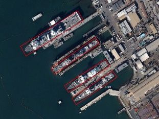
DRBox [39]         94.9      85     89.95
                                      S2ARN [40]         97.6     92.2     94.9
                                    RetinaNet-H [30]     97.34    93.6    95.47
                                       FADet [41]        98.69   92.72    95.71
                                       R3Det [30]        98.2    94.14    96.17
Remote Sens. 2020, 12, 3262               Ours           98.86   94.96    96.86                             10 of 13
                                         Ours*           98.85   95.18    97.01

    Figure
    Figure 66 provides
               provides aa visual
                           visual representation
                                  representation of
                                                 of our
                                                    our results
                                                        results on
                                                                on DOTA,
                                                                   DOTA, HRSC2016
                                                                           HRSC2016 andand UCAS-AOD
                                                                                           UCAS-AOD
datasets. It shows that our  method  has yielded fairly accurate detection results on each dataset.
datasets. It shows that our method has yielded fairly accurate detection results on each dataset.

             6. Example
      Figure 6. Example detection
                         detectionresults
                                   resultsofofour
                                               our method.
                                                  method.   The
                                                          The toptop
                                                                  rowrow   is from
                                                                       is from     DOTA,
                                                                                DOTA,     the middle
                                                                                      the middle row isrow  is
                                                                                                         from
      from HRSC2016
      HRSC2016        and
                 and the  the bottom
                         bottom  row isrow
                                        fromis UCAS-AOD.
                                               from UCAS-AOD.

5. Discussion
     The experimental results show that proposed method achieves desirable results on three different
benchmarks without additional help. This demonstrates that our method is feasible and has good
applicability. However, the proposed method also has the common problems of the current anchor-based
method: (1) the anchors need to be set according to the shapes of the objects to be detected; (2) multi-scale
anchors are used at each pyramid level, which will result in a large amount of calculation when the
objects are of various shapes; and (3) it is difficult to detect highly overlapping objects. In the future,
we will study how to reduce the dependence of the detector on multi-scale anchors and try to design a
new single-stage detector to balance performance and efficiency.

6. Conclusions
     In this study, we proposed a novel rotation-decoupled anchor matching strategy to simplify the
anchor matching process for anchor-based methods. The new strategy optimizes the way in which
the model learns the object position information without using rotating anchors. Instead of learning
the shape and angle simultaneously, as in traditional rotating anchors, the proposed strategy learns
the shape (using a horizontal anchor) and angle separately. Based on the proposed strategy, we build
a single-stage rotation detector with a simple structure. The detector is accurate and efficient and
can be further improved by adding advanced structures to it. The positive and negative sample
balance strategy is applied to deal with the foreground–background imbalance problem encountered
by single-stage detectors. We performed comparative experiments on multiple rotation detection
datasets including DOTA, HRSC2016 and UCAS-AOD. The experimental results demonstrated that
our method achieves state-of-the-art detection accuracy with high efficiency.
Remote Sens. 2020, 12, 3262 11 of 13
Author Contributions: K.A. proposed the idea, developed the algorithm, conducted the experiments and wrote
the paper. B.Z. gave many valuable suggestions and revised the paper. All authors have read and agreed to the
published version of the manuscript.
Funding: This work was supported by the project titled “Research on integrated analytic algorithms using remote
sensing big data and users’ characteristic behaviors” under Grant Y920540K80.
Conflicts of Interest: The authors declare no conflict of interest.
References
1. Liu, W.; Anguelov, D.; Erhan, D.; Szegedy, C.; Fu, C.; Berg, A.C. SSD: Single Shot Multibox Detector.
In Proceedings of the European Conference on Computer Vision, Amsterdam, The Netherlands, 8–16 October
2016; pp. 21–37.
2. Lin, T.-Y.; Goyal, P.; Girshick, R.; He, K.; Dollár, P. Focal loss for dense object detection. In Proceedings of the
IEEE International Conference on Computer Vision, Venice, Italy, 22–29 October 2017; pp. 2980–2988.
3. Zhang, S.; Wen, L.; Bian, X.; Lei, Z.; Li, S.Z. Single-shot refinement neural network for object detection.
In Proceedings of the 2018 IEEE Conference on Computer Vision and Pattern Recognition, Salt Lake City, UT,
USA, 19–21 July 2018; pp. 4203–4212.
4. Tan, M.; Pang, R.; Le, Q.V. Efficientdet: Scalable and efficient object detection. In Proceedings of the IEEE/CVF
Conference on Computer Vision and Pattern Recognition (CVPR), Nashville, TN, USA, 19–25 June 2020;
pp. 10781–10790.
5. Lin, T.Y.; Maire, M.; Belongie, S.; Hays, J.; Perona, P.; Ramanan, D.; Dollar, P.; Zitnick, C.L. Microsoft coco:
Common objects in context. In Proceedings of the 2014 European Conference on Computer Vision (ECCV),
Zurich, Switzerland, 6–12 September 2014; pp. 740–755.
6. Everingham, M.; Van Gool, L.; Williams, C.K.; Winn, J.; Zisserman, A. The pascal visual object classes (voc)
challenge. Int. J. Comput. Vision 2010, 88, 303–338. [CrossRef]
7. Liu, Z.; Hu, J.; Weng, L.; Yang, Y. Rotated region based CNN for ship detection. In Proceedings of the
24th IEEE International Conference on Image Processing (ICIP 2017), Beijing, China, 17–20 September 2017;
pp. 900–904.
8. Liu, W.; Ma, L.; Chen, H. Arbitrary-oriented ship detection framework in optical remote-sensing images.
IEEE Geosci. Remote Sens. Lett. 2018, 15, 937–941. [CrossRef]
9. Yang, X.; Sun, H.; Fu, K.; Yang, J.; Sun, X.; Yan, M.; Guo, Z. Automatic ship detection in remote sensing
images from google earth of complex scenes based on multiscale rotation dense feature pyramid networks.
Remote Sens. 2018, 10, 132. [CrossRef]
10. Tang, T.; Zhou, S.; Deng, Z.; Lei, L.; Zou, H. Arbitrary-oriented vehicle detection in aerial imagery with single
convolutional neural networks. Remote Sens. 2017, 9, 1170. [CrossRef]
11. Li, Q.; Mou, L.; Xu, Q.; Zhang, Y.; Zhu, X.X. R3 -Net: A deep network for multi-oriented vehicle detection in
aerial images and videos. arXiv 2018, arXiv:1808.05560.
12. Liao, M.; Zhu, Z.; Shi, B.; Xia, G.S.; Bai, X. Rotation-Sensitive Regression for Oriented Scene Text Detection.
In Proceedings of the IEEE Conference on Computer Vision and Pattern Recognition, San Francisco, CA,
USA, 13–18 June 2018; pp. 5909–5918.
13. Ding, J.; Xue, N.; Long, Y.; Xia, G.S.; Lu, Q. Learning RoI Transformer for Detecting Oriented Objects in Aerial
Images. In Proceedings of the IEEE Conference on Computer Vision and Pattern Recognition, Los Angeles,
CA, USA, 16–19 June 2019.
14. Yang, X.; Yang, J.; Yan, J.; Zhang, Y.; Zhang, T.; Guo, Z.; Sun, X.; Fu, K. SCRDet: Towards More Robust
Detection for Small, Cluttered and Rotated Objects. In Proceedings of the IEEE International Conference on
Computer Vision, Seoul, Korea, 27 October–2 November 2019; pp. 8232–8241.
15. Li, C.; Xu, C.; Cui, Z.; Wang, D.; Jie, Z.; Zhang, T.; Yang, J. Learning Object-Wise Semantic Representation
for Detection in Remote Sensing Imagery. In Proceedings of the IEEE Conference on Computer Vision and
Pattern Recognition Workshops, Long Beach, CA, USA, 16–20 June 2019; pp. 20–27.
16. Xu, Y.; Fu, M.; Wang, Q.; Wang, Y.; Chen, K.; Xia, G.S.; Bai, X. Gliding vertex on the horizontal bounding box
for multi-oriented object detection. IEEE Trans. Patt. Anal. Mach. Intell. 2020. [CrossRef] [PubMed]Remote Sens. 2020, 12, 3262 12 of 13
17. Pan, X.; Ren, Y.; Sheng, K.; Dong, W.; Yuan, H.; Guo, X.; Ma, C.; Xu, C. Dynamic Refinement Network for
Oriented and Densely Packed Object Detection. In Proceedings of the IEEE/CVF Conference on Computer
Vision and Pattern Recognition, Nashville, TN, USA, 19–25 June 2020; pp. 11207–11216.
18. Zhu, Y.; Du, J.; Wu, X. Adaptive period embedding for representing oriented objects in aerial images.
IEEE Trans. Geosci. Remote Sens. 2020, 58, 7247–7257. [CrossRef]
19. Xia, G.S.; Bai, X.; Ding, J.; Zhu, Z.; Belongie, S.; Luo, J.; Datcu, M.; Pelillo, M.; Zhang, L. DOTA: A Large-Scale
Dataset for Object Detection in Aerial Images. In Proceedings of the IEEE Conference on Computer Vision
and Pattern Recognition, Salt Lake City, UT, USA, 18–23 June 2018; pp. 3974–3983.
20. Liu, Z.; Liu, Y.; Weng, L.; Yang, Y. A high resolution optical satellite image dataset for ship recognition and
some new baselines. In Proceedings of the International Conference on Pattern Recognition Applications
and Methods, Porto, Portugal, 24–26 February 2017; pp. 324–331.
21. Zhu, H.; Chen, X.; Dai, W.; Fu, K.; Ye, Q.; Jiao, J. Orientation robust object detection in aerial images using deep
convolutional neural network. In Proceedings of the IEEE International Conference on Image Processing,
Quebec City, QC, Canada, 27–30 September 2015; pp. 3735–3739.
22. Girshick, R.; Donahue, J.; Darrell, T.; Malik, J. Rich feature hierarchies for accurate object detection and
semantic segmentation. In Proceedings of the IEEE Conference on Computer Vision and Pattern Recognition,
Nashville, TN, USA, 19–25 June 2014; pp. 580–587.
23. Girshick, R. Fast R-CNN. In Proceedings of the IEEE International Conference on Computer Vision, Boston,
MA, USA, 8–10 June 2015; pp. 1440–1448.
24. Ren, S.; He, K.; Girshick, R.; Sun, J. Faster r-cnn: Towards real-time object detection with region proposal
networks. In Proceedings of the Advances in Neural Information Processing Systems, Montreal, QC, Canada,
7–12 December 2015; pp. 91–99.
25. He, K.; Gkioxari, G.; Dollar, P.; Girshick, R. Mask R-CNN. In Proceedings of the 16th IEEE International
Conference on Computer Vision (ICCV 2017), Venice, Italy, 22–29 October 2017; pp. 2980–2988.
26. Redmon, J.; Divvala, S.; Girshick, R.; Farhadi, A. You only look once: Unified, real-time object detection.
In Proceedings of the 2016 IEEE Conference on Computer Vision and Pattern Recognition, Las Vegas, NV,
USA, 26 June–1 July 2016; pp. 779–788.
27. Law, H.; Deng, J. CornerNet: Detecting Objects as Paired Keypoints. In Proceedings of the European
Conference on Computer Vision, Munich, Germany, 8–14 September 2018; pp. 765–781.
28. Zhou, X.; Wang, D.; Krähenbühl, P. Objects as points. arXiv 2019, arXiv:1904.07850.
29. Tian, Z.; Shen, C.; Chen, H.; He, T. Fcos: Fully convolutional one-stage object detection. In Proceedings
of the IEEE International Conference on Computer Vision, Seoul, Korea, 27 October–2 November 2019;
pp. 9627–9636.
30. Yang, X.; Liu, Q.; Yan, J.; Li, A.; Zhang, Z.; Yu, G. R3 det: Refined single-stage detector with feature refinement
for rotating object. arXiv 2019, arXiv:1908.05612.
31. Yang, X.; Yan, J.; Yang, X.; Tang, J.; Liao, W.; He, T. SCRDet++: Detecting Small, Cluttered and Rotated
Objects via Instance-Level Feature Denoising and Rotation Loss Smoothing. arXiv 2020, arXiv:2004.13316.
32. Lin, T.Y.; Dollár, P.; Girshick, R.; He, K.; Hariharan, B.; Belongie, S. Feature Pyramid Networks for Object
Detection. In Proceedings of the IEEE Conference on Computer Vision and Pattern Recognition, Honolulu,
HI, USA, 21–26 July 2017; pp. 936–944.
33. He, K.; Zhang, X.; Ren, S.; Sun, J. Deep residual learning for image recognition. In Proceedings of the
2016 IEEE Conference on Computer Vision and Pattern Recognition, Las Vegas, NV, USA, 27–30 June 2016;
pp. 770–778.
34. Oksuz, K.; Cam, B.C.; Kalkan, S.; Akbas, E. Imbalance problems in object detection: A review. IEEE Trans.
Pattern Anal. Mach. Intell. 2020. [CrossRef] [PubMed]
35. Azimi, S.M.; Vig, E.; Bahmanyar, R.; Körner, M.; Reinartz, P. Towards multi-class object detection in
unconstrained remote sensing imagery. In Proceedings of the IEEE Asian Conference on Computer Vision,
Perth, Australia, 4–6 December 2018; pp. 150–165.
36. Howard, A.G. Some improvements on deep convolutional neural network based image classification. arXiv
2013, arXiv:1312.5402.
37. Jiang, Y.; Zhu, X.; Wang, X.; Yang, S.; Li, W.; Wang, H.; Fu, P.; Luo, Z. R2 CNN: Rotational Region CNN for
Orientation Robust Scene Text Detection. arXiv 2017, arXiv:1706.09579.Remote Sens. 2020, 12, 3262 13 of 13
38. Jian, M.; Wei, S.; Hao, Y.; Li, W.; Hong, W.; Ying, Z.; Xiang, X. Arbitrary-oriented scene text detection via
rotation proposals. IEEE Trans. Multimed. 2018, 20, 3111–3122.
39. Liu, L.; Pan, Z.; Lei, B. Learning a rotation invariant detector with rotatable bounding box. arXiv 2017,
arXiv:1711.09405.
40. Bao, S.; Zhong, X.; Zhu, R.; Zhang, X.; Li, M. Single Shot Anchor Refinement Network for Oriented Object
Detection in Optical Remote Sensing Imagery. IEEE Access 2019, 99, 1. [CrossRef]
41. Li, C.; Xu, C.; Cui, Z.; Wang, D.; Zhang, T.; Yang, J. Feature-Attentioned Object Detection in Remote
Sensing Imagery. In Proceedings of the IEEE International Conference on Image Processing, Taipei, Taiwan,
22–25 September 2019; pp. 3886–3890.
© 2020 by the authors. Licensee MDPI, Basel, Switzerland. This article is an open access
article distributed under the terms and conditions of the Creative Commons Attribution
(CC BY) license (http://creativecommons.org/licenses/by/4.0/).You can also read