SERVICE QUALITY ASSURANCE MECHANISMS FOR P2P SIP VOIP
←
→
Page content transcription
If your browser does not render page correctly, please read the page content below
Service Quality Assurance Mechanisms for P2P SIP VoIP

                         Xiaofei Liao, Fengjiang Guo, Hai Jin

                Services Computing Technology and System Lab
                        Cluster and Grid Computing Lab
                  School of Computer Science and Technology
      Huazhong University of Science and Technology, Wuhan, 430074, China
                                hjin@hust.edu.cn

       Abstract. Recently P2P (Peer-to-Peer) has been proposed to improve the
       scalability of the traditional VoIP (voice over IP) systems. However, P2P
       makes VoIP service unreliable because P2P networks probably scale up and the
       service nodes are very likely to fail or leave the P2P networks when VoIP
       service is offering. To deal with this issue, we propose a service quality
       assurance mechanism. The whole proposition includes a relay overlay
       algorithm and a dynamic relay algorithm. In the scheme, VoIP system can
       select the successor of the failed relay nodes without adding extra backup
       nodes. The simulation results demonstrate that our algorithms maintain 70%
       voice dialogs correctly in the presence of relay nodes failure with the delay
       remaining below 150ms. The results also show that the system architecture is
       feasible and scalable.

       Keywords: Voice over IP, Service quality, Backup links, Dynamic switching

1      Introduction
Voice over IP (VoIP) system is gradually replaying traditional PSTN (Public Switched
Telephone Network) telephone and becoming the key pattern of voice transportation in
NGN (Next Generation Network) due to its low cost, high flexibility and ability of
integrating multimedia information.
   The P2P technology enhances VoIP system performance, but also brings some
problems. P2P overlay network is open and extensible, but also has great differences
and dynamics. The characteristic makes P2P networks unable to meet the requirements
of VoIP system which is a kind of real-time application. When two VoIP nodes
communicate in this network, the system often has quality of service problems.
   The unreliability of service is a common issue in traditional VoIP systems, and it is
mainly due to the breakdown or departure of the service node. Traditional service
quality improvement mechanisms use RSVP (Resource Reservation Protocol) in
application-layer, and MPLS (Multi-protocol Label Switching) in physical layer for
improving service quality. The main disadvantages of those solutions are as follows:
• High costs: the cost of hardware and maintenance is increased, because it is
based on the redundant mechanisms.
• Poor scalability: the scalability of the system is subject to the constraints of the
server capacity, and the increasing number of the user means that the service
of the system is needed to be upgraded constantly.
• Performance bottleneck: those solutions do not take the property of P2P
network into account. The delay of restoration does not meet the requirement
of real-time systems.
On the other hand, in currently VoIP system, the more popular solution for
traversing the firewall is to add a relay node between the users. However, due to
property of the relay node, the system often has quality of service problems because
the service node may leave the relay overlay. In that case the VoIP call is likely to fail.
The relay overlay consists of relay nodes and relay servers. The relay node is
selected by relay server in VoIP system. In our VoIP system, the user applies to relay
server for appropriate node before initiating a call. The unreliability of this relay
service has extreme impact on the call process, because the call will be forced to be
suspended once the failure or departure of caller’s relay node.
As mentioned above, how to design an affective mechanism to find a successor of
the failed relay node is still a problem. We propose a solution of a dynamic relay
algorithm based on ICE (Interactive Connectivity Establishment) protocol. The main
idea is that a lightweight redundant mechanism for relay server is adopted. If two users
need to relay when communicating, one can use the relay server find the appropriate
node to relay. We will explain the relay-node finding mechanism between two relay
servers in the paper in detail. Before the call is initialized, the callee does not hold the
information of the caller. It will select the relay node for accomplishing ICE process.
At the same time, when the VoIP system makes the call with that relay node, it can
dynamically switch the relay node which can provide better service. The callee
automatically detects the voice quality and sends RE-INVITE (a command in SIP
protocol) request. Then the callee is staying on the phone with the caller in the case of
poor voice quality. In this case, the callee who holds the caller’s information such as
the position of its relay server could use a better relay node detecting algorithms.
In this paper we study the framework of P2P-SIP system and relay detecting
algorithms. The problem proposed is how to design service quality assurance
mechanism for P2P-SIP VoIP system to take full advantage of the properties of relay
overlay to achieve high reliability and low investment VoIP system.
The rest of this paper is organized as follows. Section 2 discusses the related work.
The detail system architecture is described in section 3. Section 4 describes our
simulation and presents the performance evaluation. We conclude this work in section
5.
2 Related Work
In this section, we give a brief overview of Skype, a real VoIP system, and related
technologies including an application-layer relay algorithm.
2.1 Skype Relay CallsSkype is the most popular P2P-based commercial VoIP system, which works around
NAT (Network Address Translation) and firewall issues by routing calls through the
machine of another Skype user with unrestricted connectivity to the Internet.
Skype client (SC) maintains a list of other Skype peers called a host cache (HC)
[4]. Other Skype peers list is empty when a SC is running for the first time, and is built
during the lifetime of a Skype client. Then, a SC can contact nodes in the host cache
(HC). Additionally, a SC has a built-in list of about seven default Skype nodes, which
are called bootstrap nodes and are used to help peers join the Skype overlay for the
first time after installation.
After joining successfully, a Skype client establishes a TCP connection with
another Skype user or a super node (SN). There are two types of nodes in the Skype
overlay: super node (SN) and ordinary node. Both SN and ordinary node run the same
Skype software. SNs are responsible for detecting online SCs, and transmitting
signaling messages between SCs [3]. To establish a call, a SC searches for the callee
machine. If they successfully contact with each other, they can directly exchange
media data with the callee machines. We can select a node as a relay node (RN) and
the call can be routed. A RN is a SN, which has sufficient bandwidth to relay a voice
or a video call.
A key aspect of Skype’s robust connectivity is its ability to traverse NAT and
firewalls by routing a video or voice call through one or more Skype relays. The
network conditions between the caller and callee machines are configured so that they
are forced to use a RN.
The success rate of relay calls depends on the network conditions, the presence of a
host cache, and caching of the callee’s reachable address. From our experiments, we
have found that Skype relay mechanism can be further improved. Because the Skype
uses private protocol and the most important problem is how to guarantee the relay
node steady and dependable.
2.2 Application-layer Relay Algorithm
The application-layer relay algorithm is a one-hop relay algorithm. It sets an overall
server in relay overlay. This server is called relay server and manages other peers. The
peers in the overlay keep the information of other nodes in the network and divide
them into some parts. This information of other nodes will be stored in a ring-structure
called Meridian [1]. It sets the radius of every ring according to the delay. The peers
ping each other and get the delay among them, and put the other nodes in its rings.
These nodes are used when the system needs a relay call.
While one peer wants to join the network, it will ask the relay server for some node
lists according to its network environment. After detecting the peers in these lists, the
new node can initialize its own rings. It will update their delay information by using
timer. The nodes send update packets to some of the peers in their rings. According to
the approach, the node can update the peers in their rings.
When users need a relay call, it sends the search packet including the information
of another user. The search algorithm will send the result back to the user who requests
the relay call. The process is as follows. First, the source peer sends the search packets
to some of its neighbors in its inner ring. The packets include IP address of the
destination node. The nodes who receive the search packets continue to transfer the
packet to the node in its own neighbors until it finds the destination node. By defining
survival time of these search packets, it can reach some nodes so that there will bemore opportunity to find the relay.
The application-layer relay algorithm is used in our early system which is called as
Cutephone. But the relay node plays important role, and its network condition is
crucially important for the call completion and service quality. Unfortunately, the relay
call is used to solve the problem when users are behind NAT and firewall. The callee
does not know the caller’s information before initializing a call in most call cases. The
relay path it selects may not be the best option.
3 Design and Architecture
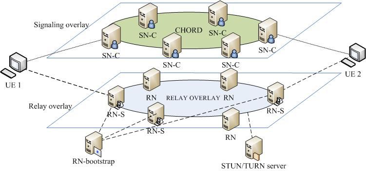
There are two levels in our VoIP system architecture, the signal overlay and the media
relay overlay, as shown in Figure 1. The upper level is signal overlay, which consists
of super node client (SN-C). The SN-C is responsible for signal transferring. The lower
level is media relay overlay, and it consists of relay servers and relay nodes. Their
respective functions are described in the following sections. A UE (the VoIP client)
could be standard traditional SIP clients or our own P2P-SIP client called Cutephone.
Cutephone is more flexible than tradition SIP clients by adding some functions to
support ICE (Interactive Connectivity Establishment).
Fig.1 P2P VoIP system structure
3.1 Design Principle
The system consists of Super Node Client (SN-C), Relay Node Server (RN-S), and
Relay Node (RN). They play different roles in the VoIP system.
SN-C combines the functions of SIP register server, SIP redirect server, and SIP
agent server. Actually SN-C has two layers. One is the tradition SIP layer, called SIP
server, and the other is the P2P overlay layer. P2P overlay is maintained by the SN-C
mainly for user orientation and user information publishing, the specific algorithm of
P2P overlay is Chord protocol.
RN-S manages the peers in relay overlay. It keeps the information of other nodes in
the network and divides them into some parts according to the delay among them. This
information of other nodes will be kept in a Meridian rings.RN transfers RTP (Real-time Transport Protocol) packets between UEs if
necessary. Besides, RN helps UEs which involves NAT traversal problem. The UEs
use ICE to traverse NAT and firewall. The relay node’s address is one of the candidate
addresses in ICE process. ICE details will be described below.
The service quality assurance mechanisms should meet the following principles:
• The system should backup the relay call link before the call initializing.
Otherwise the delay of the whole relay node switching cannot be ignored.
• The relay detecting algorithm should be divided into two different parts. As
mentioned above, the relay node which is selected before may not be the best
option. So the relay detecting algorithm must be distinguished before and after
first relay call.
• The RN-S plays an important role in relay call. Its stability will have influence
on the ICE and the relay call procedures. So we should consider the RN-S
reliability.
3.2 System Architecture Overview
According to the above principle, we adopt redundant communication mechanisms in
RN-S management of UEs. The whole architecture of relay overlay is shown in Figure
2.
Fig. 2 Relay call procedure
In Cutephone, the above relay call process and service quality assurance
mechanism are replaced by relay overlay structure. The software is four-layer
structure, as shown in Figure 3. The top layer is UI (User Interface) module, which
analyzes UE’s operation command and calls the functions provided by lower layer.
The Core API module provides the relay management function which can decide the
call modes. There are two kinds of call modes, direct and relay call, respectively. The
Media stream module uses codes module to encode and decode the audio/video data.
The NAT module uses ICE to traverse NAT and firewall. The RTP and STUN module
defines a standardized packet format for delivering audio and video over IP networks
and traverse them. The SIP module handles SIP request and response.Fig. 3 Cutephone application modules
3.3 RN-S Register
As shown in Figure 4, the process that UEs register in the relay overlay network is the
same as that UEs register in the P2P network according to a bootstrap node.
Fig. 4 RN-S registration
Specific registration process is as follows:
1) When a UE starts up, it will register in relay overlay with the bootstrap node
in the list of bootstrap it maintains.
2) UE sends requests to bootstrap node for its RN-S nodes. Then the bootstrap
node returns appropriate RN-S nodes according to UE’s geographicinformation.
3) UE tests the delay between itself and the RN-S nodes returned by bootstrap
node. Then it will check if the delay values can meet its requirements.
4) If satisfied, the registration is finished and the lowest delay nodes will be
UE’s RN-S node. Otherwise, it will serve as bootstrap node and take step 1.
The actual UE registration in relay overlay involves more than one bootstrap node.
The multi-bootstrap nodes will ensure UE’s registration in the relay overlay
successfully.
3.4 Redundancy Detecting
The process that UEs request its RN-S nodes through relay overlay network is not
different from ordinary detecting algorithm if the RN-S response acknowledgement
message is available. However, it may be failed because of the unreliable characteristic
of the overlay network. In these cases, UE will send request to its duplicate RN-S, and
then wait for the returned relay node, as shown in Figure 5. The timer in our
mechanism asks the UEs to see if the relay node server is failed or departed.
After sending request message to the RN-S and waiting for the response, the UEs
must finish the process of relay detecting. If the UEs work behind the symmetric NAT,
the relay call mode is necessary. Moreover, the relay node is important for candidate
address collection and connectivity checks in ICE technology.
Fig. 5 Redundancy detecting
3.5 NAT Traversal
The problem of NAT traversal can be resolved by ICE technology. The IETF (Internet
Engineering Task Force) has devised a suite of protocols, namely STUN (Session
Traversal Using NAT) [9], TURN (Traversal Using Relay NAT) [10], and ICE [11], to
address the limitations of the currently available NAT traversal solutions. Making a
call starts by sending a SIP INVITE message with an SDP describing on which IP
address and port the application can receive audio and/or video packets. These
addresses and ports are known as candidates. Candidates are obtained from anyfirewall engine and are inserted into the SDP of a SIP INVITE message, which is sent
to the callee.
There are 3 types of candidates: local candidate, a local IP address of the client;
reflexive or STUN candidates, an IP address of the client’s NAT (assuming they are
only behind a single NAT); and relay candidate, an address on a relay node that has
been allocated by the client.
After gathering the candidates, the caller encodes them in the SIP INVITE
message, and sends the message to the callee according to signaling overlay. In
response to the SIP INVITE, the callee sends its ICE candidates within the SDP of a
SIP provisional response, such as a SIP 183 (Session Progress), to the caller. Once the
callee has sent its ICE candidates and the caller receives them, they will start
performing ICE connectivity checks. At this time, both parties know about their peer’s
potential transport candidates. Each possible pair of local and remote candidates is
formed. A connectivity check is done by sending STUN messages from the local
candidate to the remote candidate for each pair, starting with the highest priority
candidate pair first. Both parties exchange STUN messages in this way to determine
the best possible candidate pair based on that they can communicate. Once a successful
message has been sent both ways on a single candidate pair, the connectivity check
may stop and media can be sent/received using that candidate pair.
3.6 Dynamic Relay Algorithm
The dynamic relay algorithm is based on the ICE protocol (draft-ietf-mmusic-ice-19)
and the relay detecting algorithm. It provides a self-testing and failure restoration
mechanism. Due to the breakdown or departure of relay node, the relay call service is
unreliable. For that reason, the UEs must dynamically switch relay links. In SIP
messages, the re-INVITE can modify the dialog and the parameters of the sessions at
the same time. Consequently, we use the re-INVITE message and send it to the callee
for new relay link establishment.
The other important procedure is the inquiry for a relay node. As we have said, the
relay detecting algorithm can be divided into two parts. Before the call is initialized,
we use ICE technology to determine the call link. When UEs are likely to switch the
relay links, the process of choosing relay nodes is as follows:
Step 1. UE A requests the relay node corresponding to RN-S A and RN-S B;
Step 2. for each relay Ai in Meridian rings of RN-S A;
For each relay Bi in Meridian rings of RN-S A;
if (Ai == Bi) do return relay Ai;
Else do Bi+1;
Endif;
Ai+1;
Step 3. RN-S A returns the relay node Ai to UE A, UE A makes it as relay node. Then
UE A makes a call start by sending a SIP re-INVITE message with a SDP
describing on relay node’s IP address and port the application can receive
audio and/or video packets.
Algorithm 1. Relay node detecting algorithm before switching
The specific process of dynamic relay algorithm is shown in Figure 6 and the
detailed message flow is as follows:1) SIP-client-A (UE 1) finds the poor quality of audio or video service,
according to the parameter such as packet loss ratio and delay.
2) UE 1 requests a new relay node to its relay server (RN-S 1) with the
information of UE 2’s relay server RN-S 2. According algorithm 1, the RN-S
1 and RN-S 2 work together and return the appropriate new relay node to UE
1.
3) UE 1 makes a new call by sending re-INVITE message with a SDP message
on new relay node’s address and port the application can receive audio and/or
video packets.
4) UE 1 transmits STUN packets to new relay node’s address and port. On the
other hand, UE 2 transmits the RTP packets to the address.
UE 1 RN-S 1 SN-C RN(NEW) RN-S 2 UE 2
Call established
Poor quality
Request new RN
According to algorithm 1, find a new relay node
Return new RN
Re-INVITE(new RN address)
re-INVITE re-INVITE
2xx OK 2xx OK
ACK ACK
RTP packets in STUN packets RTP packets
Fig. 6 AAA structure of P2PSIP
Considering the condition that all of the SIP clients are our applications, there may
be a problem if they send the re-INVITE message at the same time. UEs must return a
491 error message for the re-INVITE message. The clients who receive a 491 error
message will check if it is a caller. Then the caller startup a timer at the average from
2.1 to 4 second, and the callee’s timer is from 0 to 2 second.
4 Performance Evaluations
4.1 Evaluation Environment
We test our service quality assurance mechanism in the NS-2 (Network Simulation
Version 2), which is running on a node of the high performance computing cluster in
our lab. The node has two dual-processor Intel Xeon CPU and 8GB memory. We
adopt the network model of random connecting of Transit AS with Stub AS, which is
similar to the real network. With different sets of delay between, we run the system in
different network scales to evaluate the performance.
By checking the results of the simulation, we will estimate the re-hit ratio of therelay nodes, the dialog completion ratio, and the latency in our system, which is to test
the stability of the relay mechanism.
4.2 Re-hit Ratio
The re-hit ratio is an important indicator of efficiency in our algorithm. The re-hit ratio
indicates the probability that system switches relay nodes dynamically. According the
algorithm described in section 3, the relay node is crucial to service quality assurance
mechanism. Higher re-hit ratio brings better reliability of relay sub-system.
From section 3, we can see that a higher percentage of RNs in our relay overlay
does not imply that more relay calls are requested. We set the number of RN from 400-
2400.The results of re-hit ratio equals to the successful switching relay link ratio are
shown in Figure 7.
average re-hit ratio
1.0
0.8
average re-hit ratio
0.6
0.4
0.2
0.0
500 1000 1500 2000
the number of relay node
Fig. 7 Re-hit Ratio
As shown in Figure 7, the average re-hit ratio of the system decreases along with
the number of RN. The average re-hit ratio refers to the finding rate of fresh relay
nodes when UEs switch the relay links under a certain node scale. The algorithm
ensures a high re-hit rate in the low node scale. The average re-hit rate is about 90%.
But with the expansion of the RN nodes, the re-hit ratio of the algorithm also
decreases, because with the increasing of RN nodes number, the coverage TTL of
searching packets will be reduced. But exceeding a certain number of the RN nodes,
the hit rate stabilizes at a certain range, which is more than 75%, and proves the
stability of the dynamic search algorithm.
4.3 Dialog Completion Ratio
The dialog completion ratio is another important indicator of efficiency in system.
Dialog completion ratio is defined as the number of successfully completed dialogs in
a certain period of time to total dialogs. This value can be used to indicate the quality
of VoIP service.
In order to illustrate the unreliability of original VoIP system and the effectiveness
of our algorithm, we run simulations for both the original VoIP system and our reliablesystem, which contains the ICE user software. In our simulation, we uniformly set the
disabled nodes among the network and the node disabling time according to the overall
simulation time, and we run the overall 1000 sessions with relay call. The results are
shown in Figure 8.
reliable system
original system
1.00
0.95
0.90
dialog completion ratio
0.85
0.80
0.75
0.70
0.65
0.60
0.55
0.50
500 1000 1500 2000 2500
the number of RN
Fig. 8 Dialog completion ratio
The average re-hit ratio of the system decreases with the increasing of the number
RN. In spite of the relay node could fail in our system, the algorithm maintains around
98% dialogs correctly to provide the reliable SIP service. On the other hand, the dialog
completion ratio in the original VoIP system decreases along with the number of RN.
The main reason of the low ratio may be the performance of the relay detecting
algorithm, which also degrades along with the RN node scale. In our system, if the first
relay node fails, the UEs will dynamically switch another relay node.
Figure 9 shows the dialog completion ratio changing with the node failure ratio. In
the simulation we change the node failure ratio and keep the number of relay nodes
about 500. Then we can find the difference between our system and original VoIP
system. As shown in Figure 9, the dialog completion ratio decreases with the growth of
the relay node failure ratio. The original VoIP system fails even faster, under 30%
when the failure ratio is 50%, while our system is 70% at the same condition.
4.4 Latency of Switching Relay Nodes
The latency of switching relay nodes refers to the average delay of changing a relay
node between two UEs under certain situation. We will test the latency from the time
when the UE detects the poor quality to the time when one relay node has been
decided. The feasibility of the strategy also should be still useful with the expansion of
the nodes scale. If the delay value is too big or only be limited within a small node
scale, this system can not be used. In our simulation, as the shown in Figure 10, when
the system switches relay node, the latency remains about 250ms. The delay is not
satisfied, and the user can feel conversation interrupts, which comes mainly from the
delay of ICE process and relay detecting.Reliable system
Original system
1.0
0.8
Dialog completion ratio
0.6
0.4
0.2
0.0
0.9 0.8 0.7 0.6 0.5
Node failure ratio
Fig. 9 Dialog completion ratio with node failure ratio
Latancy of switch relay
300
250
Latancy of switch relay(ms)
200
150
100
50
0 500 1000 1500 2000 2500
the number of RN
Fig. 10 Latency of switch relay
5 Conclusions
In this paper, we propose a service quality assurance mechanism, which maintains the
VoIP servers quality in a relay overlay effectively. Simulation results indicate that the
system architecture is feasible and scalable.
The whole design includes relay detecting algorithm and dynamic relay algorithm.
When the VoIP system builds a call with a relay node, it can dynamically switch the
relay node with another one which can provide better service. The callee automatically
detects the voice quality and sends re-INVITE request for poor voice quality. Our work
provides an initial study on the reliable structure of P2P-SIP VoIP system.
Acknowledgments. This work is supported by Program for New Century Excellent
Talents in University under grant NCET-08-0218, China National Natural Science
Foundation (NSFC) under grant 60973133, FOK YING TUNG Education Foundation
under grant No.122007, the National Science and Technology Major Project of the
Ministry of Science and Technology of China under grant No.2010ZX-03004-001-03
and the Fundamental Research Funds for the Central Universities under grantNo.No.2010QN013.
6 References
1. Wong, B., Slivkins, A., and Sirer, E. G.: Meridian: A Lightweight Framework for
Network Positioning without Virtual Coordinates. In: The Annual ACM Conference of
the Special Interest Group on Data Communication (SIGCOMM’05), Philadelphia, PA
(2005)
2. Singh, K. and Schulzrinne, H.: Peer-to-Peer Internet telephony using SIP. In: the 15th
International Workshop on Network and Operating Systems Support for Digital Audio
and Video (NOSSDAV’05), pp.63-68 (2005)
3. Baset, S. A.: An Analysis of the Skype Peer-to-Peer Internet Telephony Protocol. In:
INFOCOM 2006, Barcelona, Spain (2006)
4. Jennings, C., Lowekamp, B., Rescorla, E., Baset, S., and Schulzrinne, H.: REsource
LOcation And Discovery (RELOAD). IETF draft draft-ietf-p2psip-reload-04 (2008)
5. Baset, S., Gupta, G., and Schulzrinne, H.: OpenVoIP: An Open Peer-to-Peer VoIP and
IM System. In: ACM SIGCOMM’08 (demo), pp.517-517 (2008)
6. Hardie, T.: Pointers for Peer-to-Peer overlay networks, nodes, or resources. IETF Draft
draft-hardie-p2psip-p2p-pointers-00 (2008)
7. Jiang, X. F. and Zheng, H.W.: Service extensible P2P protocol. IEFT Draft draft-jiang-
p2psip-sep-01 (2008)
8. Song, H., Zheng, H., and Jiang, X.: Diagnose P2PSIP overlay network failures. IETF
Draft draft-zheng-p2psip-diagnose-02 (2008)
9. Rosenberg, J., Mahy, R.: Session Traversal Utilities for NAT. IETF STUN draft behave-
rfc3489bis-10 (2008)
10. Behave, W. G. and Rosenberg, J.: Obtaining Relay Addresses from Simple Traversal
Underneath NAT. IETF TURN draft behave-turn-04 (2008)
11. Rosenberg, J.: Interactive Connectivity Establishment (ICE): A Protocol for Network.
IETF ICE draft mmusic-ice-18 (2007)
12. Address Translator (NAT) Traversal for Offer/Answer Protocols
13. Guha, S. and Daswani, N.: An Experimental Study of the Skype Peer-to-Peer VoIP
System. In: IPTPS’06 (2006)
14. Xie, H. and Reng, Y.: A Measurement based Study of the Skype Peer to Peer VoIP
Performance. In: IPTPS’07, Bellevue, WA (2007)
15. Fei, T., Tao, S., and Guerin, R.: How to select a good alternate path in large peer-to-peer
system. In: IEEE INFOCOM’06 (2006)
16. Shansi, R., Lei, G. and Zhang, X.: ASAP: an AS-Aware Peer-Relay Protocol for High
Quality VoIP. In: the 26th IEEE International Conference On Distributed Computing
System (2006)
17. Shu, T., Kuai, X. and Antonio, E.: Improving VoIP quality through path switching. In:
IEEE INFOCOM’05 (2005)You can also read