Reliability of the DRAGON Product Family
←
→
Page content transcription
If your browser does not render page correctly, please read the page content below

Reliability of the DRAGON Product Family
Application Note

Introduction
This application note provides an overview
of the performance of the DRAGON product
family (in this case, LEDs without plastic
lenses) as well as a summary of the most
important customer-relevant LED data with
respect to its effect on LED lifetime.

In general, it should be noted that in spite of
the high reliability of LEDs, a high total or
system reliability can only be achieved if all
factors and parameters are taken into
consideration      (see    Application   Note
                                                     means of lead-free IR reflow soldering
"Reliability and Lifetime of LEDs").
                                                     techniques.
A possible influence on the reliability of the
                                                     As with all other LEDs from OSRAM Opto
LED by the user is essentially specified by          Semiconductors, the DRAGON product line
the chosen operating conditions, by
                                                     also fulfills current RoHS guidelines and
consideration of the processing details, and         contains no lead or other hazardous
for high power LEDs such as the DRAGON
                                                     substances.
product family, for example, by the provision
of adequate thermal management.
                                                     Construction and aging
DRAGON product family                                mechanisms of DRAGON LEDs

The DRAGON product family was primarily              The construction of the DRAGON product
developed for applications which require             family is based on a thermally-optimized
maximum light combined with low space                package design, consisting of a prefabri-
requirements and the highest demands on              cated plastic package with an integrated
lifetime.                                            heat sink and connection contacts
Due to their performance and design,                 (Figure 1).
DRAGON LEDs are suitable for diverse
areas of lighting and illumination technology,       An advantage of this design is that it permits
ranging from general lighting to automotive          mutual exchangeability within the product
applications and the replacement of                  family, thus increasing customer flexibility
miniature incandescent lamps.                        due to identical solder pad layouts.

Designed for high-volume production, they            A primary factor which influences the lifetime
can be processed with all established                of an LED is the temperature of the light-
populating techniques and mounted by                 emitting layer or junction temperature (Tj)
                                                     with which the LED is driven in the
                                                     application.

January, 2014                             Page 1 of 14
Figure 1: DRAGON basic package – thermally optimized

With a lower junction temperature, the
expected lifetime of the LED is increased.
Therefore, it is important that good thermal
management is not only implemented within
the LED, but also on the part of the system
in the application (see "Thermal Manage-
ment of Golden DRAGON LEDs").

Since it is not possible to measure the
junction temperature within an application, it
is recommended that the temperature be              Figure 2: Primary heat flow in the
measured at an external reference point             DRAGON products
instead.
For OSRAM Opto Semiconductors, this                 If the operating current is increased in an
reference point is the temperature TS of the        environment that remains constant, the
"solder point". The "solder point" represents       dissipation increases and the junction
the transition from the active thermal path of      temperature rises as a result. This means
the LED package to the solder pads of the           that the choice of operating current has an
circuit board, and is dependent on the              effect on the degradation behavior of the
packaging technology.                               LED.
With the DRAGON LEDs, it is recommended
to measure the solder point temperature             Figure 3 shows the brightness levels and
directly next to the long side of the package,      thermal behavior of the individual LED types
by means of a thermocouple.                         within the DRAGON product family.

January, 2014                            Page 2 of 14

When considering the aging characteristics            In black packages, this effect is not
of an LED, not only must the thermal aging            noticeable, since the reflector is already dark
of the chips be take into account, but the            to begin with (e.g. the Diamond DRAGON).
aging of the package material must be
considered as well.                                   With long-wavelength chips (λ > 550 nm) the
Here, the wavelength of the light source              initial reflector aging does not occur.
employed plays a decisive role.
Short wavelengths lead to aging of the                Reflector aging also occurs for longer-
reflector in the package. It can be observed          wavelength devices, but this is primarily
here, that the shorter the wavelength of the          influenced by temperature and progresses
emitted radiation, the faster the aging               more slowly than with shorter wavelengths.
process occurs.                                       This occurs in parallel to chip aging or to a
                                                      minimal extent after chip aging and is
A degradation of the reflective properties of         therefore not observable as a separate
the package takes place, which in turn leads          process by the user.
to a decrease in intensity of the emitted light.
This behavior has been observed with blue,            As a light source, highly efficient semicon-
green and white devices.                              ductor chips of the latest thin film technology
                                                      from OSRAM Opto Semiconductors are
After the conclusion of reflector aging, chip         employed in the DRAGON LEDs.
aging becomes the determining factor for the          For the colors Deep Blue, Blue, True Green,
further aging behavior of the LED.                    and White, the chip technology is based on
                                                      the semiconductor material indium gallium
Reflector aging appears in white/light                nitrite (ThinGaN); for the colors Amber,
packages. The short wavelength radiation              Yellow and Red, it is based on aluminum
leads to a browning of the reflector.                 indium gallium phosphide (ThinFilm).

Figure 3: Brightness level within the DRAGON product family

January, 2014                              Page 3 of 14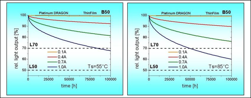
Figure 4a: Degradation characteristics of the DRAGON products with ThinGaN
semiconductor chips with a white package

In Figure 4, the typical degradation                    maintenance (L)" and "mortality" (B) can be
characteristics for the molded silicon                  found in the application note "Reliability and
DRAGON products with ThinGaN (4a) and                   Lifetime of LEDs".
ThinFilm (4b) are schematically shown.
Table 1 summarizes the individual phases of             The following sections provide specific
the aging characteristics of the DRAGON                 information about the lifetime and degrada-
product family, with respect to technology (or          tion characteristics of the DRAGON product
packaging).                                             family.
                                                        Here, a distinction is made between the
Additional information about factors which              ThinGaN (Deep Blue, Blue, True Green and
influence the lifetime and reliability of LEDs          White) and ThinFilm technologies (Amber,
as well as the failure parameters " lumen               Yellow and Red).

                ThinGaN technology with           Thinfilm and
                white package                     ThinGaN technology with dark package
                Initial chip aging (positive or
 Phase I                                          Initial chip aging (positive or negative)
                negative)
 Phase II       Reflector aging

 Phase III      Normal degradation phase          Normal degradation phase

 Phase IV       Chip aging                        Chip aging
Table 1: Degradation phases of DRAGON LEDs

January, 2014                              Page 4 of 14
Figure 4b: Degradation characteristics of DRAGON products with ThinFilm or ThinGaN
semiconductor technology with a black package

January, 2014                     Page 5 of 14

Lifetime and degradation charac-                  Example: A blue Golden DRAGON (LB
teristics of DRAGON LEDs with                     W5SM) is driven with a current of 350 mA. A
                                                  solder point temperature of TS = 55°C was
ThinGaN technology                                measured. In this case, the expected lifetime
                                                  L70/B50 amounts to 90 khrs(*).
The diagrams in Figure 5 graphically show
the expected lifetime L70/B50 of the
                                                  For the application, the degradation
individual DRAGON LED types LEDs with
                                                  characteristics of the LED over the lifetime
ThinGaN technology in relationship to the
                                                  are important. In this regard, OSRAM Opto
solder point temperature TS
                                                  Semiconductors has carried out intensive
                                                  long-term analyses and developed models
The resulting TS curves are displayed in
                                                  that reflect the expected lifetime of the LED.
color for different operating conditions.
                                                  The following degradation diagrams for the
The typical Rth value of the DRAGON type
                                                  individual DRAGON LED types (Figures 6a -
was used as a basis for calculation of the
                                                  6d) are based on TS=55° and TS=85°C for
curves. For operating currents, various
                                                  various operating currents such as the
typical currents such as the minimum and
                                                  minimum and maximum permissible current,
maximum allowable current or the grouping
                                                  the respective grouping current and the half
current and half-grouping current were used.
                                                  or doubled grouping current. The dashed
                                                  lines represent the L70/B50 and L50/B50
                                                  limits.

Figure 5: Lifetimes(*) for various DRAGON LED types with ThinGaN technology with
respect to TS
January, 2014                          Page 6 of 14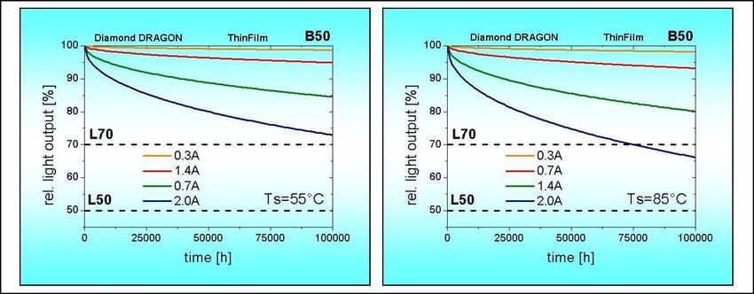
The diagrams depicted describe estimates           conditions, product variations, selected
based on extrapolations and represent              brightness binning, humidity and other
average value curves (B50). The actual             influencing factors.
values may differ due to specific application

Figure 6a: Degradation characteristics(*) of the Golden DRAGON with ThinGaN technology
for TS = 55°C and TS = 85°C (grouping current IF = 0.35 A)

Figure 6b: Degradation characteristics(*) of the Golden DRAGON Plus with ThinGaN
technology for TS = 55°C and TS = 85°C (grouping current IF = 0.35 A)

January, 2014                           Page 7 of 14

Figure 6c: Degradation characteristics(*) of the Platinum DRAGON with ThinGaN
technology for TS = 55°C and TS = 85°C (grouping current IF = 0.7 A)

Figure 6d: Degradation characteristics(*) of the Diamond DRAGON with ThinGaN
technology for TS = 55°C and TS = 85°C (grouping current IF = 1.4 A)

January, 2014                       Page 8 of 14

Lifetime and degradation                          For operating currents, various typical
characteristics of DRAGON LEDs                    currents such as the grouping current for the
                                                  type or the minimum and maximum
with ThinFilm technology                          permissible current were used.
The diagrams in Figure 7 graphically show         The measuring principle is the same as for
the expected lifetime L70/B50 of the              the ThinGaN technology.
individual DRAGON products with ThinFilm
technology (InGaAIP) in relationship to the       The following degradation diagrams (Figures
solder point temperature TS.                      8a – 8d) for the individual Dragon LED types
For the ThinFilm technology, the aging            are based on solder point temperatures of
characteristics are not only dependent on         TS=55° and TS=85°C for various operating
the junction temperature but also on the          currents (analogous to the currents shown in
current density.                                  the diagrams of Figure 7). The L70/B50 and
                                                  L50/B50 limits are shown with dashed lines.
The resulting TS curves are displayed in
color for different operating conditions.

Figure 7: Lifetimes(*) of various DRAGON LED with ThinFilm technology with respect to TS

January, 2014                          Page 9 of 14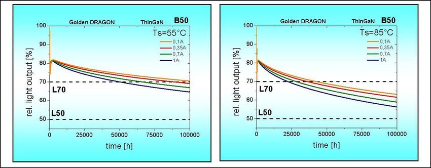
Figure 8a: Degradation characteristics(*) of the Golden DRAGON with ThinFilm technology
for TS = 55°C and TS = 85°C (grouping current IF = 0.35 A)

Figure 8b: Degradation characteristics(*) of the Golden DRAGON Plus with ThinFilm
technology for TS = 55°C and TS = 85°C (grouping current IF = 0.35 A)

Figure 8c: Degradation characteristics(*) of the Platinum DRAGON with ThinFilm
technology for TS = 55°C and TS = 85°C (grouping current IF = 0.7 A)
January, 2014                       Page 10 of 14
Figure 8d: Degradation characteristics(*) of the Diamond DRAGON with ThinFilm
technology for TS = 55°C and TS = 85°C (grouping current IF = 1.4 A)

Overview of typical lifetime values of the DRAGON devices

1                            2                             3
    TS = 70°C; IF = 750 mA       TS = 70°C; IF = 850 mA;       TS = 70°C; IF = 1000 mA;
4                            5                             6
    TS = 95°C; IF = 600 mA       TS = 95°C; IF = 700 mA;       TS = 95°C; IF = 900 mA;

January, 2014                             Page 11 of 14
7 8 9
TS = 55°C; IF = 1000 mA; TS = 55°C; IF = 1400 mA; TS = 125°C; IF = 1000 mA;
10 11 12
TS = 70°C; IF = 750 mA; TS = 70°C; IF = 850 mA; TS = 70°C; IF = 1000 mA;
Summary
Due to their thermally optimized package As can be seen from the diagrams, the
design, the LEDs of the DRAGON product LEDs of the DRAGON group achieve an
family offer the designer or developer an average lifetime of up to 100,000 hours in
excellent starting point for the design of combination with adequate thermal manage-
highly-efficient, reliable light sources with ment and depending on the chosen
exceptionally long lifetimes. operating conditions. This corresponds to
In addition to their robustness and reliability around 11.5 years of continuous operation.
the package of the DRAGON line permits
unprecedented flexibility for the customer.
With just one circuit board layout, a variety
of requirements with respect to brightness
and lifetime can be fulfilled in one or more
application areas.
___________________________________
(*) The failure criterion is the specified percentage of
the initial luminous intensity. The numbers above
represent estimations based on extrapolations. The
actual value can differ depending on, but not limited to
selected brightness binning, temperature at the LED,
forward current, humidity, production variations and
specific application conditions. As a result, these
values can not be warranted or guaranteed.
January, 2014 Page 12 of 14Appendix Don't forget: LED Light for you is your place to be whenever you are looking for information or worldwide partners for your LED Lighting project. www.ledlightforyou.com Authors: S. Weise, Th. Zahner, Th. Lutz, A. Stich ABOUT OSRAM OPTO SEMICONDUCTORS OSRAM, with its headquarters in Munich, is one of the two leading lighting manufacturers in the world. Its subsidiary, OSRAM Opto Semiconductors GmbH in Regensburg (Germany), offers its customers solutions based on semiconductor technology for lighting, sensor and visualization applications. OSRAM Opto Semiconductors has production sites in Regensburg (Germany) and Penang (Malaysia). Its headquarters for North America is in Sunnyvale (USA). Its headquarters for the Asia region is in Hong Kong. OSRAM Opto Semiconductors also has sales offices throughout the world. For more information go to www.osram-os.com. DISCLAIMER PLEASE CAREFULLY READ THE BELOW TERMS AND CONDITIONS BEFORE USING THE INFORMATION. IF YOU DO NOT AGREE WITH ANY OF THESE TERMS AND CONDITIONS, DO NOT USE THE INFORMATION. The Information shown in this document was produced with due care, but is provided by OSRAM Opto Semiconductors GmbH “as is” and without OSRAM Opto Semiconductors GmbH assuming, express or implied, any warranty or liability whatsoever, including, but not limited to the warranties of correctness, completeness, merchantability, fitness for a particular purpose, title or non-infringement. In no event shall OSRAM Opto Semiconductors GmbH be liable - regardless of the legal theory - for any direct, indirect, special, incidental, exemplary, consequential, or punitive damages related to the use of the Information. This limitation shall apply even if OSRAM Opto Semiconductors GmbH has been advised of possible damages. As some jurisdictions do not allow exclusion of certain warranties or limitations of liability, the above limitations or exclusions may not apply. The liability of OSRAM Opto Semiconductors GmbH would in such case be limited to the greatest extent permitted by law. OSRAM Opto Semiconductors GmbH may change the Information at anytime without notice to user and is not obligated to provide any maintenance or support related to the Information. The Information is based on specific Conditions and, therefore, alterations to the Information cannot be excluded. January, 2014 Page 13 of 14
Any rights not expressly granted herein are reserved. Except for the right to use the Information included
in this document, no other rights are granted nor shall any obligation be implied requiring the grant of
further rights. Any and all rights or licenses to patents or patent applications are expressly excluded.

Reproduction, transfer, distribution or storage of part or all of the contents of this document in any form
without the prior written permission of OSRAM Opto Semiconductors GmbH is prohibited except in
accordance with applicable mandatory law.

January, 2014                               Page 14 of 14
You can also read