R@CKCOOLAIR APPLICATION GUIDE

Page created by Elaine Webb
 
CONTINUE READING
R@CKCOOLAIR APPLICATION GUIDE
APPLICATION
GUIDE
                          R@CKCOOLAIR

                             RHC - RNC - RNV

"In Row" close control unit for high density
systems

3 > 51 kW

                                     RACKCOOLAIR-AGU-1310-E

                                     lennoxemeia.com
R@CKCOOLAIR APPLICATION GUIDE
TABLE OF CONTENTS

R@CKCOOLAIR

APPLICATION GUIDE
                                                                                                Ref : RACKCOOLAIR-AGU-1310-E

            CODIFICATION - QUICK VIEW                                                                           3

       1. GENERAL DESCRIPTION                                                                                   4

       1. GENERAL DATA
            RHC units                                                                                           10
            RND units                                                                                           12
            RNV units                                                                                           16

       3. INSTALLATION
            Lifting and transport                                                                               20
            Clearances                                                                                          20
            Positioning                                                                                         20

       4. DIMENSIONAL DATA
            RHC units                                                                                           21
            RND units                                                                                           24
            RNV units                                                                                           26
                                      Version 2008

                                                                                           Our company’s products comply
  Product designed and manufactured under quality management                                 with European standards.
           systems certified ISO 9001 and ISO 14001.

 All the technical and technological information contained in this manual, including any drawing and technical descriptions provided
 by us, remain the property of Lennox and must not be utilised (except in operation of this product), reproduced, issued to or made
 available to third parties without the prior written agreement of Lennox.

Application Guide • R@CKCOOLAIR-AGU-1310-E                                                                                             •1•
R@CKCOOLAIR APPLICATION GUIDE
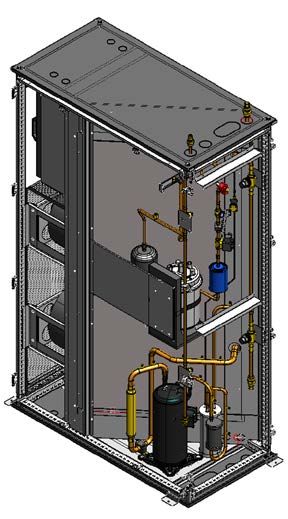
•2•   Application Guide • R@CKCOOLAIR-AGU-1310-E
R@CKCOOLAIR APPLICATION GUIDE
CODIFICATION

                         RND 0260
                                         026 =   Capacity in kW

                                        RHC =    Chilled water

                                        RND =    Direct expansion with remote condenser

                                        RNV =    Direct expansion with condensing unit

QUICK VIEW
RHC                                                        0200             0250          0450   0510

Total cooling capacity                            kW         22              28,6         42,9   58,2

Airflow rate                                     m3/h      4000             5300          9000   11000

Width                                            mm         300              300          600    600

RND                                                        0100             0260          0400   0450

Total cooling capacity                            kW        11,2             25,8         40,0   44,7

Airflow rate                                     m3/h      2700             5000          9000   9000

Width                                            mm         300              600          600    600

RNV                                                        0140             0240          0330

Total cooling capacity                            kW        12,8             24,2         33,5
                                                  3
Airflow rate                                     m /h      3100             4400          4400

Width                                            mm         300              300          300

Application Guide • R@CKCOOLAIR-AGU-1310-E                                                               •3•
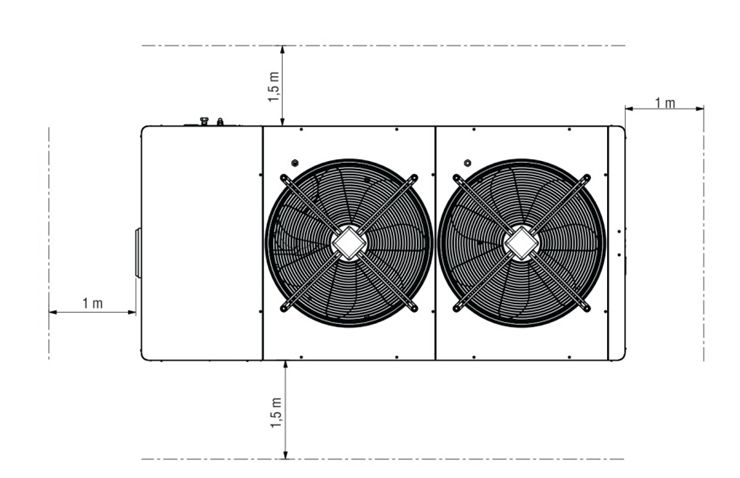
R@CKCOOLAIR APPLICATION GUIDE
GENERAL DESCRIPTION

The self-contained R@CKCOOLAIR units are especially designed           The internal design of the units has been focused on efficiency
to be installed in technological environments where a spot cooling     and reliability keeping easy accessibility: all components, including
is needed.                                                             fans, valves, electrical components, etc. are accessible from
As all LENNOX products, R@CKCOOLAIR represents the state               front and back sides.
of the art between technology and design : the low depth (1200         The exclusive use of primary brands components and a fully
or 1000 mm) allows compatibility with standard server rack.            integrated development process (CAD + CAM, CAE) stands
Furthermore the innovative design and the high tech selected           for highest possible quality level regarding efficiency, reliability,
colours make this units complementary to the last generation           maintenance time, pre and after sales support.
of IT devices.

VERSIONS
The R@CKCOOLAIR is available in three different versions :

RHC – Chilled water
                                                                       RND & RNV - Direct expansion
Chilled water unit with high performance coil and modulating
water valve which distinguishes for:                                   In the RND range, the compressor is located inside the unit and
                                                                       connected to a remote condenser.
  • Highest specific cooling capacity (W/m2) due to the large heat
    exchanger surface;
  • Precise temperature control (PID type regulation);                 The RNV range is a split unit connected to a condensing unit.
  • The possibility to increase return air temperature, thus to
    rise – while keeping the cooling capacity stable – the medium
    chilled water temperature. This results in a maximized EER
    of the chiller and extends the Free-Cooling operation.

                                  RHC

                                                                                      RND                                  RNV

Both versions are equipped with variable speed EC motor compressors which guarantee:
  • Precise temperature control (PID type regulation);
  • Reduced power consumption at partial load;
  • Avoiding of electrical peaks and the compressor’s mechanical stress in ON/OFF cycles;
  • Extension of the application field.

This is the solution for small and medium size installations where no chilled water system is available or where no chiller can be placed
or where site specific constraints do not allow for water in the Datacenter.
Adjusting the facility configuration with the distance between indoor and outdoor unit allows a simple and economic installation.

•4•                                                                                     Application Guide • R@CKCOOLAIR-AGU-1310-E
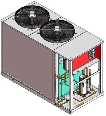
R@CKCOOLAIR APPLICATION GUIDE
GENERAL DESCRIPTION

APPLICATION
The R@CKCOOLAIR ranges can be used
in In-Row application with cold or hot aisle    Keep in mind that :
or in In-Rack application.                      Fan consumption = k*[Air Flow]3

The positioning of the R@CKCOOLAIR              Alternatively and optionally available is the
unit next to the Server itself minimizes        “automatic airflow control” which keeps the
the ventilation consumption needed to           airflow constant in case of variable pressure
overcome pressure drops from ducting or         drops of the system, or the “Delta P control”
raised floor systems.                           for a pressure control in the cold aisle.
Using plug fans with backward curved
blades (in contrast to axial fans) guarantees
a maximum stability in airflow even in most     The positioning of this type of product
packed Server-racks whereas the optionally      offer another big advantage, the cooled
available EC fans allow an efficient            air does not go through the raised floor.
modulation of the air volume.                   Usually when the data center requirements
                                                change the raised floor becomes clogged
The advanced control modulates the airflow      with cables which then obstruct the airflow
in combination with either the chilled water    to the diffusion grid, degrading the quality
valve (RHC) or the compressor speed (NRD        of the cooling and increasing the pressure
/ NRV) and thus significantly reduces the       drop and then the energy consumption.
electrical consumption of the airflow.

IN-RACK

                           This airflow configuration is designed         AIRFLOW CONFIGURATIONS
                           to cool down the server-rack only and
                           not all the server-room. It is a really
                           spot cooling solution : where and when
                           you need it

                                                                                                                                 Left
                                                                                                                      ft
                                                                                                                and le
                                                                                                        Right
Two temperature control zones
                                                                                       Right
Our advanced control allow to manage two different zones, top
and bottom, according to the distribution of appliances in the rack
or the type of appliance for example one UPS* at the bottom               You can select left, right or left and right configuration.
and server bays on top.                                                   Obviously in this case the server-racks have to be equipped with
                                                                          doors and back with solid panels or glass-doors.

The In-Rack configuration is only allowed for the units 300 mm
wide and 1200 mm long, as well as server-rack 42U (2000mm)
and 46U (2200 mm).

                                                                        *Uninterruptible power supply

Application Guide • R@CKCOOLAIR-AGU-1310-E                                                                                              •5•
R@CKCOOLAIR APPLICATION GUIDE
GENERAL DESCRIPTION

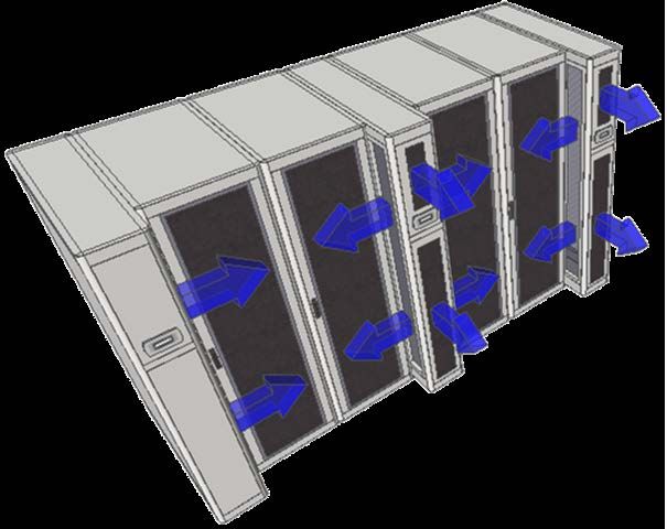
IN-ROW                                                                                      Air mixing decreases the air intake

                          This airflow configuration is designed for
                          hot or cold aisle.
                          Both hot and cold air containment
                          improve significantly the efficiency of
                          data center cooling systems due to the
                          fact that we eliminate the mixing of hot
                          and cold air. In the traditional approach
                          the cooled air floods the entire space
                          and hot air is mixed with.
                          Separate the cooled and hot air the
                          cooling system can be set to a higher                                    Traditional installation
                          temperature thereby increasing its
                          efficiency and the energy saving.
                          By this way we also remove less
                          humidity from the air and then reduce
                          the humidification requirement.

Pressure control
In this type of installation pressure control is required. First, an
overpressure in the aisle could damage the server, secondly, in
keeping the pressure at the same level than outside, air leakage
and trouble with door opening is avoided. Our advanced control                Cold aisle installation
with the EC fans allow such precise control. In this case for
better efficiency we recommend to draw the pressure sensor
pipe in the aisle.

AIRFLOW CONFIGURATIONS

The different possibilities of airflow configurations allow many           - Right illustration : other possibilities when we use units of 1200 mm
solutions :                                                                with racks of 1000 mm. The discharge can be at the end or/and
- Below left illustration : traditional configuration with rack and unit   right, left you can imagine any combination.
of the same dimension 1000 mm or 1200 mm.

•6•                                                                                           Application Guide • R@CKCOOLAIR-AGU-1310-E
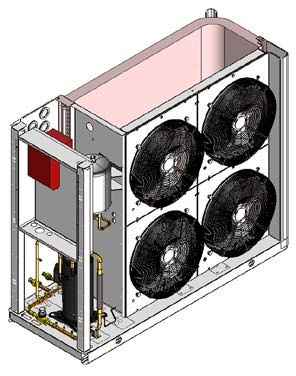
R@CKCOOLAIR APPLICATION GUIDE
GENERAL DESCRIPTION

STRUCTURE DESCRIPTION                                                      COOLING CAPACITY READING (RHC)
R@CKCOOLAIR units are designed with a self-supporting frame                As an option on the RHC chilled water range, we can propose
and all components are produced using sophisticated computer               In/Out water temperature sensors, water flow meter or both, in
driven machines and special tools.                                         this last case the instantaneous capacity of the unit can be read
All sheet metals are galvanized and all external panels are                on the display or from the BMS.
powder coated (RAL 7035) giving to the units the same image
and quality as last generation of IT devices. The shape of the
units is characterized with the curved edges with variable radium.         WATER/REFRIGERANT CONNECTIONS
All fixing elements are made in stainless steel or in non-corroding
materials. The drain pan is made of stainless steel in order to            For chilled water and DX units you can chose connection to the
ensure long time operation without damages.                                top or to the bottom of the unit.
All panels are thermally insulated with a polyurethane foam class
1 according UL 94 norms: this material, thanks to the open cells,
gives good performances in sound absorption.                               CONDENSATION PUMP
                                                                           Our units are equipped with two drain pans (AISI 430 stainless
                                                                           steel EDX), one specific underneath the cooling coil and another
ELECTRICAL CONTROL BOARD                                                   one at the bottom of the unit. As an option, we can provide
The electric control board is constructed and wired in accordance          condensation pump on board.
with Directives 73/23/EEC and 89/336/EEC and related standards.
The board may be accessed through a door after the main switch
has been turned off. All the remote controls use 24V signals               LEVELLING FEET
powered by an insulating transformer situated on the electric              For the Indoor unit we can provide 4 adjustable feet to align the
control board.                                                             unit with the server-rack. This option is not suitable for cold/hot
 • The mechanical safety devices such as the high pressure                 aisle application (due to air bypass underneath the unit).
   switched are of the kind that trigger directly; their efficiency will
   not be affected by any faults occurring in the microprocessor
   control circuit, in compliance with 97/23 PED.                          WATER LEAKAGE DETECTOR
                                                                           Option specially required for chilled water unit, but keep in mind
WARNING : For RNV range, the power supply of indoor and outdoor            that our units are equipped with 2 drain pans.
units are separated. Especially on sizes 0240 and 0330 where
we have 230V/1/50Hz for indoor and 400V/3/50Hz for outdoor.
                                                                           FIRE ALARM
                                                                           We can also provide smoke detector and fire detector.
FILTRATION
The R@CKCOOLAIR is equipped as a standard with G3 filters,
but in option G4 and M5 are available.
Our filter can be proposed with clogged-filter sensor. In this case        CONDENSING CONTROL
you get an alarm when your filters are dirty.                              Our DX units are equipped as a standard with fan speed control
                                                                           to ensure enough pressure drops across the expansion device
                                                                           in operation with outside temperature below 20°C.
                                                                           But below -15° and down to -30°C, we can propose as an option
HUMIDITY CONTROL                                                           a flooding device in order to flood the condenser internal surface
The advanced control manages the humidification and                        allowing the right condensing temperature even in case of strong
dehumidification. The unit provide O-10V signal to drive an external       and cold wind. This device is shipped as a kit consisting of a
humidifier but for the 600 mm width unit an internal 3kg/h steam           back pressure valve, a receiver, a safety valve and mounting
humidifier can be proposed as an option.                                   instructions: the installation is very simple and has to be done
                                                                           just close to the condensing unit at bottom side.

DUAL POWER SUPPLY
Our unit can be equipped with optional DPSS,(Dual Power Supply
System for automatic changeover from main line to UPS)

Features :
 • Switching time = ~2 seconds (due to an electromechanical
   commutation)
 • Unit stop time = ~30 seconds (due to the restart time of the
   microprocessor)

The DPSS is designed on specific unit around its maximum
absorbed power and current. We can provide different type of
solutions, according to the size of the electrical panel.

Application Guide • R@CKCOOLAIR-AGU-1310-E                                                                                                •7•
R@CKCOOLAIR APPLICATION GUIDE
GENERAL DESCRIPTION

ADVANCED CONTROL
The microprocessor built into the unit allows the different operating
parameters to be controlled from a set of pushbuttons situated
on the electric control board:
  • Switching On/Off - Modulation of compressor to maintain the
    temperature set point T inside the shelter.
  • Alarm management :
    - High / Low pressure;
    - Dirty filters alarm (optional);
    - Air flow alarm.

  • Alarm signalling.
  • Display of operating parameters.                                    OPTIONS :
  • RS232, RS485 serial output management (optional).                    • The units are equipped with their own display but you can
  • Phase sequence error (not displayed by the control, but                add a remote one
    prevents the compressor from starting up) (only for direct           • Air volume measurement - automatic constant airflow control
    expansion units).                                                      and visualization
  • As standard, LAN connection up to 8 units                            • Delta pressure control : required for cold/hot aisle application
                                                                         • Many possibilities of communication through different protocols

                                                                        See microprocessor control manual for further details, also in
                                                                        relation to particular customer specifications.

FEATURES SUMMARY
Standard                                                                Options and accessories
  • Spot cooling: where and when you need it                             • Clogged filter sensors
  • Airflow switch                                                       • Dehumidification/Humidification control with humidity sensor
  • Full accessibility                                                     option (steam humidifier in 600 mm units)
  • Display of 3-way water valve mixing percentage                       • Additional temperature and humidity sensors
  • High pressure radial fans with backward curved blades : EC           • Automatic airflow control with display visualization
    plug fans with continuous speed modulation                           • Fire and smoke sensors
  • Modulating airflow in accordance to the cooling capacity for         • Water leakage detector
    a much higher energy saving                                          • Condensate water pump
  • High efficiency hydrophilic finned coil with aluminum structure      • Water flow meter with current cooling capacity display
  • Two drain pans made of AISI 430 stainless steel EDX                  • Integrated IT Racks and Hotspot Cooling solutions – propo-
  • Hydraulic connections from the top or from the bottom                  sition des rack avec l’armoire
  • Powder-coated metal sheet structure                                  • Alarm option with extra potential free contacts
  • Fully insulated panels                                               • Serial cards for protocols : Modbus / Lonworks / Bacnet /
  • 2 or 3 way water valve, modulating by means of a 0-10 V                Trend
    signal                                                               • pCOWEB Hardware: Ethernet card for protocols: Bacnet /
  • Several different airflow configurations                               SNMP
  • Two separate zones control – At the top and the bottom of            • DATAWEB Software: Ethernet card for Web connectivity
    the unit                                                             • Touch-Screen colour graphic display
  • Condensing controls: Built-in control for air-cooled units
    (modulating fan-speed control) with dedicated automatic
    breaker
  • Lockable panels
  • Programmable control with LCD display
  • LAN connection up to 8 units

•8•                                                                                     Application Guide • R@CKCOOLAIR-AGU-1310-E
GENERAL DESCRIPTION

AIRFLOW CONFIGURATIONS OVERVIEW
Allowed airflow configurations according to dimensions.

1000x300x2000                 ■          ■          ■          ■            ■          ■       ■
1000x300x2200                 ■          ■          ■          ■            ■          ■       ■
1200x300x2000                 ■          ■          ■          ■            ■          ■       ■       ■       ■         ■
1200x300x2200                 ■          ■          ■          ■            ■          ■       ■       ■       ■         ■
1200x600x2000                 ■          ■          ■          ■            ■          ■       ■
1200x600x2200                 ■          ■          ■          ■            ■          ■       ■

SIDES IDENTIFICATION
Allowed airflow configurations according to dimensions.

                                                                    Left side                                   Right side

                                                                   Rear side                                    Front side

CABINET DIMENSIONS OVERVIEW (indoor unit)
Dimensions allowed according to the type and size.

                                        RHC                                          RND                       RNV

                        0200      0250       0450       0510       0100         0260   0400    0450    0140    0240     0330
1000x300x2000             ■         ■                                                                      ■    ■            ■
1000x300x2200             ■         ■                                                                      ■    ■            ■
1200x300x2000             ■         ■                                ■                                     ■    ■            ■
1200x300x2200             ■         ■                                ■                                     ■    ■            ■
1200x600x2000                                 ■           ■                      ■         ■       ■
1200x600x2200                                 ■           ■                      ■         ■       ■

Application Guide • R@CKCOOLAIR-AGU-1310-E                                                                                       •9•
GENERAL DATA

 R@CKCOOLAIR - RHC
 Chilled water unit
 R@CKCOOLAIR                                                               RHC 0200                    RHC 0250                  RHC 0450                RHC 0510

  Indoor operating conditions                                       24°C 30°C 35°C 24°C 30°C 35°C 24°C 30°C 35°C 24°C 30°C 35°C
  Temperature - Relative humidity                                   50% 35% 26% 50% 35% 26% 50% 35% 26% 50% 35% 26%

  Total cooling capacity (1                                             13,0    20,5     26,2     18,1    28,3   36,1       30,4   46,2   59,1        36,1   57,0    74,2

  Sensible cooling capacity                                kW 13,0              20,5     26,2     18,1    28,3   36,1       30,4   46,2   59,1        36,1   57,0    74,2

  Fan absorbed power                                                             0,6                      0,8                      2,1                        2,5

  KVS valve                                                                                     6,5                                              25

  Voltage                                                                           230 V/1 Ph/50 Hz                                  400 V/3 Ph/50 Hz

  Water flow rate                                           l/h 2395 3780 4840 3150 4919 6297 4805 7375 9429 6376 9997 12830

  Water pressure drop                                     kPa 19,2              48,2     78,7     30,6    75,8 123,2        40     92,2 150,6 34,5           86,3 146,1

  Airflow rate                                           m3/h                   4000                     5300                      9000                      11000

  Dimensions
                                                          mm                           300 x 2000 x 1200                              600 x 2000 x 1200
  Length x Height x Depth

  Weight                                                    kg                   130             135                               250                       280

 Water : 10-15 °C

 Power supply / Storage conditions
                                                                                                             0200                                     0450
  Model                                                                                 RHC
                                                                                                             0250                                     0510
  Power supply                                                                                           230 Vac ± 10%                      400 Vac ± 10%
  Indoor unit                                                                                               1/50Hz                            3+N/ 50Hz
                                                                                                                      from -10 °C to +60 °C
  Storage conditions
                                                                                                                      90 % relative humidity

 Operating limits
                                                                               Relative humidity ≤ 65%
                                                         45 °C
                                    Indoor temperature

                                                         35 °C

                                                         20 °C
                                                                 5 °C                   15 °C                       30 °C

                                                                               Chilled water temperature

• 10 •                                                                                                            Application Guide • R@CKCOOLAIR-AGU-1310-E
GENERAL DATA

R@CKCOOLAIR - RHC
Chilled water unit

Legend
                                                      7
  1   Chilled water coil

      Electrical panel (removable for access to the
  2   fans )
                                                                                         2
  3   Double stainless steel drain pan                                                                5

  4   Fan                                             1

  5   Air filter
                                                                                         4
  6   Water valve

                                                                                                                                   3
  7   Water connections from the top
                                                                                                      6
  8   Water connections from the bottom                                                                                            8

BASIC COOLING CIRCUIT
                                                                                   Legend

                                                                                    1   Chilled water inlet

                                                                                    2   Chilled water outlet

                                                                                    3   3-way valve

                                                                                    4   Plug fan

                                                                                    5   Coil heat exchanger

                                                                                    6   Breather valve

                   3-way valve                            2-way valve               7   Breather valve

WATER VALVE
Modulating valves allow high precision in controlling the rack temperature
 • 3 way valve for constant flow systems
 • 2 way valve for variable flow. In this case, free cooling application range will be extended thanks to the increase of return water
   temperature once the load decreases

Model                                                      RHC 0200/RHC 0250                              RHC 0450/RHC 0510
Brand / Type of valve                                        Controlli / VMXT2                            Johnson / VG7802RT
PN valve                                                            16                                           16
Dimension (inch)                                                   3/4"                                         1" 1/2

All RHC units are supplied with 3- or 2-way valves with 0-10V signal regulation.

Application Guide • R@CKCOOLAIR-AGU-1310-E                                                                                       • 11 •
GENERAL DATA

 R@CKCOOLAIR - RND
 Direct expansion unit with remote condenser

 Cooling circuit                                                               Cooling components
 The entire refrigerating circuit is assembled in our production line           • Molecular mesh activated-alumina filter dryer.
 including all pipe work and using only primary brand components.
                                                                                • Flow indicator with humidity indicator (indications are provided
 The workers involved in the welding and pipe work process are
                                                                                  directly on the sight glass).
 qualified by a third part according to CEE 97/23. The units are
 precharged with dry nitrogen.                                                  • High and low pressure switches.
                                                                                • Schraeder valves for checks and/or maintenance.

 Compressors
 On RND units, only primary brand of scroll compressors is used,               Maximum pressure switch
 BLDC scroll for inverter application are installed.                           The high pressure switch stops the compressor when the outlet
 On close control units, BLDC scroll compressor is the best solution           pressure exceeds the set value.
 in terms of efficiency and reliability. The compression ratio is very
 close to the typical operating condition of these units, giving the           Warning: do not attempt to change the setting of the maximum
 maximum in terms of COPs. The perfect balanced pressures at                   pressure switch: Should the latter fail to trip in the event of a
 start-up gives high reliability to the EC motor, especially in this           pressure increase, the pressure relief valve will open.
 application with frequent start-ups.
 All motors are thermally protected with an internal sensors chain:
                                                                               The high pressure switch must be manually reset; this is possible
 in case of overload, this sensor opens without giving contacts
                                                                               only when the pressure falls below the differential set (see above).
 to the connection box.

 Electronic expansion valve                                                    Minimum pressure switch
                                                                               The low pressure switch stops the compressor when the inlet
 Standard feature on our DX range, the expansion valve is a mass
                                                                               pressure falls below the set value for more than 1 second. The
 flow regulator ensuring the right refrigerant flow according to
                                                                               switch is automatically reset when the pressure rises above the
 the superheating after the evaporator. The mass flow depends
                                                                               set differential (see above).
 mainly from the % of opening and from the delta pressure
 available across the valve. Mechanical valves have a very little
 modulating capacity and, to ensure the mass flow, require a
 significant pressure difference over it.
 The R@CKCOOLAIR uses an electronic driven valve that ensures
 a high modulation capacity thanks to the large shutter stroke :
 this solution allows to decrease the minimum differential pressure
 over the valve, thus reducing the condensing temperature in
 middle and winter seasons. In this periods the reduction of
 energy consumption reaches 51 % guaranteeing significant
 money savings and CO2 emission reduction.

 Setting of control and safety devices

  Control device                                                   Activation                    Differential                 Resetting

  Maximum pressure switch                           Bar-g                38                            4                        Manual

  Minimum pressure switch                           Bar-g                2.0                          1.5                     Automatic

  Condensation modulating control devices
                                                    Bar-g                18                           10                            -
  (DX versions)

  Time laps between two compressor starts                s               480                           -                            -

• 12 •                                                                                         Application Guide • R@CKCOOLAIR-AGU-1310-E
GENERAL DATA

RND : DX unit with remote condenser
R@CKCOOLAIR                                                                RND 0100                                                       RND 0260
Compressor frequency                                     Hz       30                 70                           120           30            70           120

Total cooling capacity                                   kW       3,1               7,6                           11,2          7,6          16,6          25,8

Sensible heat ratio                                                                                                        1

Compressor absorbed power                                kW       0,7               1,5                           2,7           1,2           3,2          6,9

Compressor absorbed current                                  A    3,1               7,2                           13,0          1,9           4,8          10,5

Evaporator airflow rate                                 m /h
                                                         3
                                                                 700           1600                               2700         1500          3000          5000

Fan absorbed power                                       kW      0,05           0,12                              0,40          0,11         0,21          0,50

Voltage                                                                 230 V/1 Ph/50 Hz                                               400 V/3 Ph/50 Hz
                                                                 1 x EC motor compressor - Twin
Compressor type                                                                                                                1 x EC motor compressor - Scroll
                                                                            Rotary
Dimensions
                                                        mm              300 x 2000 x 1200                                              600 x 2000 x 1200
Length x Height x Depth
Weight                                                    kg                      135                                                        365

R@CKCOOLAIR                                                                RND 0400                                                       RND 0450
Compressor frequency                                     Hz       30                 70                           120           30            70           120

Total cooling capacity                                   kW      12,9           26,5                              40,0         14,9          30,9          44,7

Sensible heat ratio                                                                                                        1

Compressor absorbed power                                kW       1,9               5,4                           11,3          2,4           6,5          14,4

Compressor absorbed current                                  A    2,9               8,2                           17,2          3,6           9,9          21,9

Evaporator airflow rate                                 m3/h     2700          5500                               9000         2700          5500          9000

Fan absorbed power                                       kW      0,20           0,65                              2,10         0,20          0,65          2,10

Voltage                                                                                                           400 V/3 Ph/50 Hz

Compressor type                                                                                    1 x EC motor compressor - Scroll
Dimensions
                                                        mm                                                        600 x 2000 x 1200
Length x Height x Depth
Weight                                                    kg                      368                                                        375

Operating conditions :
Indoor : 30°C/35% - Outdoor : 35°C

Power supply / Storage conditions                                                    Operating limits
                                                       0260                                                              Relative humidity ≤ 65%
 RND                                 0100              0400
                                                       0450
                                                                                                  32 °C

                              230 Vac ± 10%       400 Vac ± 10%
                                                                             Indoor temperature

Power supply
                                 1/50Hz             3+N/ 50Hz                                     28 °C

                                     from -10 °C to +60 °C
Storage conditions
                                     90 % relative humidity

                                                                                                  18 °C
                                                                                                          20 °C                                     40°C    45 °C

                                                                                                                     Condenser air temperature

Application Guide • R@CKCOOLAIR-AGU-1310-E                                                                                                                       • 13 •
GENERAL DATA

 R@CKCOOLAIR - RND
 Direct expansion unit with remote condenser

                               RND 0100                              RND 0260/0400/0560

                                           11
               7
                                           10                                                        11
               4
                                           9
                                                                                                     10

                                                           12
                                                                                                      9

                                                                                                      8

                                                                                                      7
                                                            4
                                                                                                      6

          12                               3

                                           2                3
                                                                                                      2

         13

                                                                                                      5

                                           1

                                                                                                      4

                                                                                            4

  Legend

   1     Radial fan                             8   Humidifier

   2     Electrical panel                       9   Dry filter

   3     Inverter                               10 Sight glass

   4     EC motor compressor                    11 Expansion valve

   5     Air filter                             12 Liquid receiver

   6     Silencer                               13 Evaporator

   7     Oil separator

• 14 •                                                               Application Guide • R@CKCOOLAIR-AGU-1310-E
GENERAL DATA

R@CKCOOLAIR - RND
BASIC COOLING CIRCUIT

          Long distance kit

                                             Supply limit

          Option

Legend

 1   Inverter driven compressor                             10 Liquid receiver

 2   HP Pressure switch                                     11 Condenser

 3   Pressure probe (opt.)                                  13 Safety valve

 4   Ball valve                                             14 Check valve

 5   Refrigerant filter                                     15 Solenoid valve

 6   Sight glass                                            16 Oil solenoid valve

 7   Thermostatic valve                                     17 Bypass valve - Long distance kit

 8   Evaporator                                             18 Oil separator

 9   LP pressure switch

Application Guide • R@CKCOOLAIR-AGU-1310-E                                                        • 15 •
GENERAL DATA

 R@CKCOOLAIR - RNV
 Direct expansion unit condensing unit

 Cooling circuit                                                               Cooling components
 The entire refrigerating circuit is assembled in our production line           • Molecular mesh activated-alumina filter dryer.
 including all pipe work and using only primary brand components.
                                                                                • Flow indicator with humidity indicator (indications are provided
 The workers involved in the welding and pipe work process are
                                                                                  directly on the sight glass).
 qualified by a third part according CEE 97/23. The units are
 prechargerd with dry nitrogen.                                                 • High and low pressure switches.
                                                                                • Schraeder valves for checks and/or maintenance.

 Compressors
 On RNV units, only primary brand of scroll compressors is used,               Maximum pressure switch
 BLDC scroll for inverter application are installed.                           The high pressure switch stops the compressor when the outlet
 On close control units, BLDC scroll compressor is the best solution           pressure exceeds the set value.
 in terms of efficiency and reliability. The compression ratio is very
 close to the typical operating condition of these units, giving the           Warning: do not attempt to change the setting of the maximum
 maximum in terms of COPs. The perfect balanced pressures at                   pressure switch: should the latter fail to trip in the event of a
 start-up gives high reliability to the EC motor, especially in this           pressure increase, the pressure relief valve will open.
 application with frequent start-ups.
 All motors are thermally protected with an internal sensors chain:            The high pressure switch must be manually reset; this is possible
 in case of overload, this sensor opens without giving contacts                only when the pressure falls below the differential set (see above).
 to the connection box.

                                                                               Minimum pressure switch
 Electronic expansion valve                                                    The low pressure switch stops the compressor when the inlet
                        Standard feature on our DX range, the                  pressure falls below the set value for more than 1 second. The
                        expansion valve is a mass flow regulator               switch is automatically reset when the pressure rises above the
                        ensuring the right refrigerant flow checking           set differential (see above).
                        the superheating at the evaporator outlet.
                        The mass flow depends mainly from the
                        % of opening and from the delta pressure
                        available across the valve. Mechanical
                        valves have a very little modulating
                        capacity and, to ensure the mass flow,
                        a significant Delta P across it has to be
                        maintained.
                        The R@CKCOOLAIR uses an electronic
                        driven valve that ensures a high modulation
                        capacity thanks to the large shutter stroke
                        : this solution allows to decrease the
 minimum differential pressure over the valve, thus reducing the
 condensing temperature in middle and winter seasons. In this
 periods the reduction of energy consumption reaches 51 %
 guaranteeing significant money savings and CO2 emission
 reduction

 Setting of control and safety devices

  Control device                                                   Activation                    Differential                 Resetting

  Maximum pressure switch                           Bar-g                38                            4                        Manual

  Minimum pressure switch                           Bar-g                2.0                          1.5                     Automatic

  Condensation modulating control devices
                                                    Bar-g                18                           10                            -
  (DX versions)

  Time lapse between two compressor starts               s               480                           -                            -

• 16 •                                                                                         Application Guide • R@CKCOOLAIR-AGU-1310-E
GENERAL DATA

R@CKCOOLAIR - RNV
Direct expansion unit condensing unit

R@CKCOOLAIR                                                                                        RNV 0140                   RNV 0240                    RNV 0330

Indoor unit

Compressor frequency                                                               Hz        30       70      120     30         70        120     30        70      120

Total cooling capacity                                                            kW         3,9     8,1      12,8    7,8        16        24,2    12,8      23      33,5

Sensible heat ratio                                                                          1        1        1       1         1          1       1        0,9     0,83

Evaporator airflow rate                                                                     900      1800     3100   1650       2900      4400    2900      3600     4400
                                                                                  kW
Fan absorbed power                                                                          0,08     0,17     0,38    0,14      0,35      0,99     0,3      0,56     0,99

Voltage                                                                                                                 230 V/1 Ph/50 Hz
Dimensions
                                                                                  mm                                   300 x 2000 x 1200
Length x Height x Depth
Outdoor condensing unit

Compressor frequency                                                               Hz        30       70      120     30         70        120     30        70      120

Compressor absorbed power                                                         kW         0,6     1,7      4,3     1,2       3,2         7       2        5,2     10,7

Compressor absorbed current                                                            A     2,9     8,2      20,8    1,8       4,9       10,6     3,1       7,9     16,2

Number of scroll compressors                                                                                                     1

Condenser airflow rate                                                           m3/h                3500                       9300                        16280

Soud power level                                                                                      62                         72                          73
                                                                               dB(A)
Sound pressure level (10 m free field)                                                                34                         44                          45

Voltage                                                                                       230 V/1 Ph/50 Hz                           400 V/3 Ph/50 Hz
Dimensions
                                                                                  mm          1270 x 880 x 500         1565 x 1300 x 600            1990 x 1485 x 950
Length x Height x Depth
Weight                                                                                 kg            100                        332                          162

Operating conditions :
Indoor : 30°C/35% - Outdoor : 35°C

Power supply / Storage conditions
 RNV

                                  Indoor unit
 Power supply
                                   Outdoor unit

                                                                                                                     from -10 °C to +60 °C
 Storage conditions
                                                                                                                     90 % relative humidity

                                                                                             Relative humidity ≤ 65%
Operating limits
                                                                       32 °C
                                                  Indoor temperature

                                                                       28 °C

                                                                       18 °C
                                                                               20 °C                                   40°C      45 °C

                                                                                            Condenser air temperature

Application Guide • R@CKCOOLAIR-AGU-1310-E                                                                                                                            • 17 •
GENERAL DATA

 R@CKCOOLAIR - RNV
 Direct expansion unit condensing unit

                                                                    Legend
 Indoor unit
                                                                      1   Radial fan

                                                                      2   Electrical panel

                                                                      5   Air filter

                                                                      9   Dry filter

                                                                     10 Sight glass

                                                                     11 Expansion valve

                                                                     13 Evaporator

 Outdoor units
  RNV 0140                                         RNV 0240

               3

               2

                                                            3
                                                                                                      1
               4                                            2

                                5   1                       4

  RNV 0300

                                           3

         1                                 2
                                                                                                          5

                                           4

                                           5

  Legend

   1     Liquid receiver                       4    EC motor compressor

   2     Electrical panel                      5    Oil separator

   3     Inverter

• 18 •                                                              Application Guide • R@CKCOOLAIR-AGU-1310-E
GENERAL DATA

R@CKCOOLAIR - RNV
BASIC COOLING CIRCUIT

                                             Supply limit
     Evaporator                                                                  Condenser

                                                                  Supply limit

Legend

 1    Inverter driven compressor                            10 Liquid receiver

 2    HP Pressure switch                                    11 Condenser coil

 3    Pressure probe (opt.)                                 13 Safety valve

 5    Refrigerant filter                                    14 Check valve

 6    Sight glass                                           15 Solenoid valve

 7    Thermostatic valve                                    16 Oil solenoid valve

 8    Evaporator                                            18 Oil separator

 9    LP pressure switch                                    19 Shout off valve

Application Guide • R@CKCOOLAIR-AGU-1310-E                                                   • 19 •
INSTALLATION

 Lifting and transport                                                    Positioning
 While the unit is being unloaded and positioned, utmost care must        Keep in mind the following aspects when choosing the best site
 be taken to avoid abrupt or violent movements. The unit must be          for installing the unit and the relative connections:
 handled carefully and gently; avoid using machine components              • positioning and dimensions of the coupling flanges;
 as anchorages or holds and always keep it in an upright position.
                                                                           • location of power supply;
 The unit should be lifted using the pallet it is packed on; a
 transpallet or similar conveyance means should be used.                   • solidity of the supporting floor.

 Warning: In all lifting operations make sure that the unit is securely   It is recommended to first prepare holes in the floor/wall for passing
 anchored in order to prevent accidental falling or overturning.          through the power cables and for the air outlet (downflow units).
                                                                          The dimensions of the air outlet and the positions of the holes for
                                                                          the screw anchors and power cables are shown in the dimensional
                                                                          drawing (see the documentations delivered together with the unit)

 CLEARANCES
 The RHC air-conditioning unit is suitable for all environments
 except aggressive ones. Do not place any obstacles near the
 units and make sure that the air flow is not impeded by obstacles
 and/or situations causing back suction.

 The following steps should be carried out to ensure proper
                                                                                                       RNV 0240
 installation:                                                                                   Outdoor unit - Top view
   • Apply a anti-vibration rubber lining between the unit and the
     bottom.                                                                                           Heat exchanger side
   • Position the unit on the floor

                                                                                                                                           Exchanger side
                                                                               Electrical box

                                                                                                       RNV 0300
                                                                                                 Outdoor unit - Top view

                                                                                                       Heat exchanger side

                            RNV 0140
                                                                           Electrical box

                    Outdoor unit - Top view

                                                                                                       Heat exchanger side

• 20 •                                                                                          Application Guide • R@CKCOOLAIR-AGU-1310-E
DIMENSIONAL DRAWINGS

RHC 0200 - RHC 0250
In Rack (1200 mm)

                                                        2

                                                                                        110
                                                                        2x Ø 30

                                               45
                                                                                                   Power inlet
                                                                                                   2x Ø 40

                                                210
                                                                    1

                                                                                              80
                                                                                        110
                                                45
                                                       100     70                 60
                            300                                          1200
                                                      66,5   170         727      170   66,5

                                                                                        92
                                                      18

                                                                                        1778
                                             (2020)
                   2002

                                                                                        132

                                                         1
     Cooling water inlet
 1
     3/4" gas                                                                     60
                                                              100
                                                                                          110
                                                80

     Cooling water outlet
 2
                                                                                        80

     3/4" gas
                                               140

                                                                                        110
                                                80

                                                               2

Application Guide • R@CKCOOLAIR-AGU-1310-E                                                                       • 21 •
DIMENSIONAL DRAWINGS

 RHC 0200 - RHC 0250
 In ROW (1200 mm)

                                                                                                110
                                                                2              2x Ø 30

                                                        45
                                                                                                        Power inlet
                                                                                                        4x Ø 40

                                                        210
                                                                           1

                                                                                                   80
                                                                                                110
                                                        45
                                                               100   70                  60
                                    300
                         91,5      117     91,5                                  1200                     70   160    70
                                             406 95

                                                               18

                                                                                                                      130
                                             262

                                                      (2020)
                       2002

                                                                                                                           1777
                                             1144

                                                                                                                      95
                                             95

                              70           70                   1
                                          160
                                                                     100                 60
                                                                                                110
                                                        80

         Cooling water inlet
                                                                                                  80

   1
         3/4" gas
                                                       140

         Cooling water outlet
   2
                                                                                                110

         3/4" gas
                                                        80

                                                                     2

• 22 •                                                                                        Application Guide • R@CKCOOLAIR-AGU-1310-E
DIMENSIONAL DRAWINGS

RHC 0200 - RHC 0250
In ROW (1000 mm)
                                                                                   Power inlet
                                                                        2            2x Ø 40

                                                                                                 110
                                                                                      1

                                                                                                       80
                                                               105          70             60

                                                                                 47

                                                                                                 110
                                          300
                                  91,5    117    91,5                                                   70   160   70

                                                   95

                                                                   18

                                                                                                                   130
                                                   406
                                                   262

                                                          (2020)
                              2002

                                                                                                                     1777
                                                   1144
                            490

                                                                                                                   95
                                                   95

                                     70          70
                    165

                                                                                  1000
                                                160

                                                               105          105           60       110

     Cooling water inlet
                                                                                  80

                                                                                                 80
 1
     3/4" gas                                                 2
     Cooling water outlet
 2
     3/4" gas
                                                                                                 110

                                                                            1      Power inlet
                                                                                     2x Ø 40

Application Guide • R@CKCOOLAIR-AGU-1310-E                                                                                  • 23 •
DIMENSIONAL DRAWINGS

 RND 0100

                         Horizontal air flow (rear-front)                              Side air flow (left and right)

                                          2                                                                     2
                                     98                                                                    98

                                                                                                   86
                                86

                                                                                                                     1
                                86

                                                                                                 86
                                                                185
                              140

                                                                                               140
               312                                            63,5    63,5           312                             1217
                                          1
                                60

                                                                                                                60
                                                                                               52.5
                                                               52,5

                                                                                            1905
                                                                             2010
 2010

                                                            1905
                       1290

                                                               52,5

                                                                                               52.5
                       53

                                                                                            68,5                     710          68,5
        63,5          63,5                    1217                                                      185                 185
                     185
                                          1                                                                1
                                     98                                                     140       98
                               140

                                                                                           86
                              86

                                                                                              86
                               86

                                          2                                                                2

           Liquid line inlet
   1
           Rotalock 1" - Ø 12
           Gas line outlet
   2
           Rotalock 1" - Ø 12

• 24 •                                                                              Application Guide • R@CKCOOLAIR-AGU-1310-E
2
                                                    Horizontal air flow (rear-front)

                                                                                                         215
                                                                                                                 Drain pan
                                                                                                         80

                                                                                            150
                                                                                                                  3

                                                                                                         235

                                                                                       114,5 383 114,5
                                                                                                     1
                                                               612                                                                                        470

                                                                                                                                                   52,5

                                                                                                         100

                                                                         97.5
                                                                                                                                                                                                                                                  DIMENSIONAL DRAWINGS

                                                                                                                                                    71          71

Application Guide • R@CKCOOLAIR-AGU-1310-E
                                                                                                                                                                                                               RND 0260 - 0400 - 0450 (1200 mm)

                                                                                                                                           1904

                                                                                1814

                                             2009
                                                                                       2109
                                                                                                                                                                                                         815

                                                                         97,5
                                                                                                                                                  52,5
                                                                                                                                                                                                   400

                                                    94,5       423       94,5                                      1217

                                                                                                                                                                         Liquid line inlet
                                                                                                                                                                     1
                                                                                                                                                                         Rotalock 1" - Ø 16
                                                                                                   1                                                                     Gas line outlet
                                                                                                                          80   190                                   2
                                                                                                                                                                         Rotalock 1" 1/4 - Ø 22

                                                                                                         114,5
                                                                                                                                     111                                 Humidifier water supply
                                                                                                                  Power                                                  3/4" gas male
                                                                                        97,5                                                                         3
                                                                                                                    inlet
                                                                                                                                     390

                                                                                                         383
                                                                                                                                                                         Humidifier water drain
                                                                                                                                                                         Ø 32
                                                                                                                                     111

                                                                                                         114,5
                                                                                                   2

  • 25 •
2 pre-cut holes

   • 26 •
                                                         Ø 30              power inlet
                                                                           2xØ 40

                                                                                         Frontal grid
                                                                                         dimension
                                                                                                                                  RNV 0140 - 0240 - 0330 (1000 mm)
                                                                                                                                                                     DIMENSIONAL DRAWINGS

                                             Back grid
                                             dimension

                                                                                                            Refrigerant inlet
                                                                                                        1
                                                                                                            Rotalock ODS - Ø 16
                                                                                                            Refrigerant outlet
                                                                                                        2
                                                                                                            Rotalock ODS - Ø 22

Application Guide • R@CKCOOLAIR-AGU-1310-E
2 pre-cut holes
                                                                        Ø 30
                                                                                          Power inlet
                                                                                          2x Ø 40
                                                                                                                                                                                 DIMENSIONAL DRAWINGS

Application Guide • R@CKCOOLAIR-AGU-1310-E
                                                                                                                                              RNV 0140 - 0240 - 0330 (1200 mm)

                                                                                                        Back grid
                                                                                                        dimension

                                                                   Side grid dimen-
                                                                                sion

                                             Frontal grid dimen-
                                             sion

                                                                                                                        Refrigerant inlet
                                                                                                                    1
                                                                                                                        Rotalock ODS - Ø 16
                                                                                                                        Refrigerant outlet
                                                                                                                    2
                                                                                                                        Rotalock ODS - Ø 22

  • 27 •
DIMENSIONAL DRAWINGS

 RNV 0140
 Outdoor units

                                                                                                    150
                                                                    Power supply inlet
                            1270                         380   83
                                                                                                      70

                                                                                                           412.5
 850

                                             882                                                           B
                                                   150

                                                                                                           71.5
                                                                                                      40
                                                         450
 32

                                                                                           A         90
  34

                                             15
                                             420
                                             15
  34

             197.5           875     197.5

               Refrigerant inlet
         A
               Rotalock ODS - Ø 12
               Refrigerant outlet
         B
               Rotalock ODS - Ø 16

• 28 •                                                              Application Guide • R@CKCOOLAIR-AGU-1310-E
DIMENSIONAL DRAWINGS

RNV 0240
Outdoor units

                                    1

                                             Rotalock ODS - Ø 22

                                                                   Rotalock ODS - Ø 16
  Power supply inlet

                                                                   Refrigerant outlet
                                  2

                                             Inlet
                                                 1

                                                                       2

Application Guide • R@CKCOOLAIR-AGU-1310-E                                      • 29 •
DIMENSIONAL DRAWINGS

 RNV 0330
 Outdoor units

                                1
     Power supply inlet

                                                                             Rotalock ODS - Ø 22

                                                                                                   Rotalock ODS - Ø 16
                                    2

                                                                                                   Refrigerant outlet
                                                                             Inlet
                                                                                 1

                                                                                                       2

• 30 •                                           Application Guide • R@CKCOOLAIR-AGU-1310-E
lennoxemeia.com

  sales offices :

   Belgium and Luxembourg                  Russia
          + 32 3 633 3045                     +7 495 626 56 53

   France                                  Spain
          +33 1 64 76 23 23                   +34 902 533 920

   Germany                                 Ukraine
          +49 (0) 40 589 6235 0               +380 44 461 87 79

   ITALY                                   United Kingdom and Ireland
          + 39 02 495 26 200                  +44 1604 669 100

   Netherlands
          + 31 332 471 800

   Poland
          +48 22 58 48 610                OTHER COUNTRIES :

                                           LENNOX DISTRIBUTION
   Portugal
                                               +33 4 72 23 20 00
          +351 229 066 050

                                             Due to Lennox’s ongoing commitment to quality, the specifications,
                                             ratings and dimensions are subject to change without notice and
                                             without incurring liability.
                                             Improper installation, adjustment, alteration, service or
                                             maintenance can cause property damage or personal injury.
                                             Installation and service must be performed by a qualified installer
                                             and servicing agency

RACKCOOLAIR-AGU-1310-E
You can also read