POST-PROCESS (PPG) REFERENCE GUIDE - VISUALCAM-PPG 2021 - MECSOFT CORPOTATION - MECSOFT ...
←
→
Page content transcription
If your browser does not render page correctly, please read the page content below
Post-Process (PPG)
Reference Guide
 VisualCAM-PPG 2021
           Tuesday, February 23, 2021

                                        MecSoft Corpotation
                                          © Copyright 1998-2021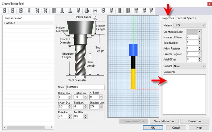
VisualCAM 2021 Post-Processor Generator
                            by MecSoft Corporation

     User Notes:
     ________________________________
     ________________________________
     ________________________________
     ________________________________
     ________________________________
     ________________________________
     ________________________________
     ________________________________
     ________________________________
     ________________________________
     ________________________________
     ________________________________
     ________________________________
     ________________________________
     ________________________________
     ________________________________
     ________________________________
     ________________________________
     ________________________________
     ________________________________
Contents                        2

Table of Contents

Welcome                                                                                                                                                                                      4

Quick Start                                                                                                                                                                                  5

PPG Decoded Guide                                                                                                                                                                            8

Resource Guide                                                                                                                                                                               9

Good Things to Know                                                                                                                                                                        10

Use Legacy Post                                                                                                                                                                            21
            1 Dialogs
                   ................................................................................................................................... 22
                      Post Processor..........................................................................................................................................................
                                         File Brow ser                                                                                                                                         22
                      PPG Editor    .......................................................................................................................................................... 23
                      Variable List Dialog
                                    .......................................................................................................................................................... 24
            2 PPG Editor
                  ................................................................................................................................... 25
                      General        .......................................................................................................................................................... 25
                      StartEnd       .......................................................................................................................................................... 29
                      Tool Change .......................................................................................................................................................... 30
                      Setup          .......................................................................................................................................................... 33
                      Spindle        .......................................................................................................................................................... 34
                      Feed Rate      .......................................................................................................................................................... 36
                      Motion         .......................................................................................................................................................... 38
                      Circle         .......................................................................................................................................................... 40
                      Helical/Spiral .......................................................................................................................................................... 43
                      Multi Axis Motion
                                     .......................................................................................................................................................... 44
                      Cutter Com pensation
                                     .......................................................................................................................................................... 47
                      Cut Motion Start/End
                                     .......................................................................................................................................................... 48
                      Cycles         .......................................................................................................................................................... 49
                      Miscellaneous  .......................................................................................................................................................... 52
                      Variables      .......................................................................................................................................................... 54
            3 Macros
                  ................................................................................................................................... 63
                      Macros       .......................................................................................................................................................... 63
                      How to edit Macros
                                   .......................................................................................................................................................... 64

Use Programmable Post                                                                                                                                                                      65
            1 Selecting
                   ...................................................................................................................................
                           a Programmable Post                                                                                                         65
            2 Writing
                   ...................................................................................................................................
                       Scrips                                                                                                                          66
            3 Post Events
                   ................................................................................................................................... 67
            4 Post Event
                   ...................................................................................................................................
                            List                                                                                                                       68
            5 Post Variables
                   ...................................................................................................................................
                                   List                                                                                                                70
            6 Example
                  ...................................................................................................................................
                         Script                                                                                                                       77

© 2021 MecSoft Corporation

                                                                                                                                                                                                     2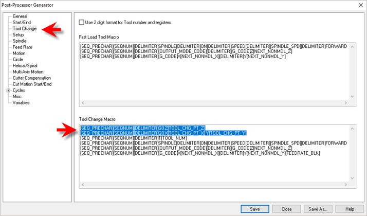
3    VisualCAM 2021 Post-Processor Generator

Find More Resources                                                   83

        Index                                                         84

                                                 © 2021 MecSoft Corporation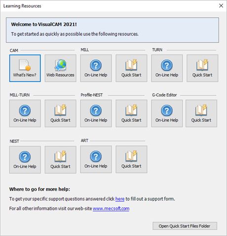
Welcome   4

Welcome

                                       VISUALCAM2021

                                Prefer Printed Documentation? Click Here!
          The VisualCAD/CAM Post-Processor Generator is used to edit post processor files (SPM Files).
          These files are used by VisualCAD/CAM during toolpath post-processing. VisualCAD/CAM reads in
          a user specified SPM file, each file corresponding to a single machine tool controller, and
          generates the post-processed output using the rules resident in these files. Users have the ability
          to edit these files to modify these rules, thereby controlling the output that VisualCAD/CAM
          generates.
          Using the VisualCAD/CAM Post-Processor Generator, these SPM files can be edited by following
          these steps:
          First choose the required SPM file to edit from the Post Processor File Browser. After selecting the
          file, it can be edited using the Editor dialog. The format of various output blocks, such as motion,
          feed rates, spindle etc., can be edited by selecting the appropriate tabs in this dialog.
          In addition to predefined block definitions, you can add startup codes as well as termination
          codes specific to the controller and shop practices. These blocks can be user-defined statements
          that may contain built in variables.
                                            On-line help compiled on: Tuesday, February 23, 2021

                     Related Topics
                     Good Thinks to Know
                     Post Processor File Browser
                     Main Editor
                     Variable List Dialog

© 2021 MecSoft Corporation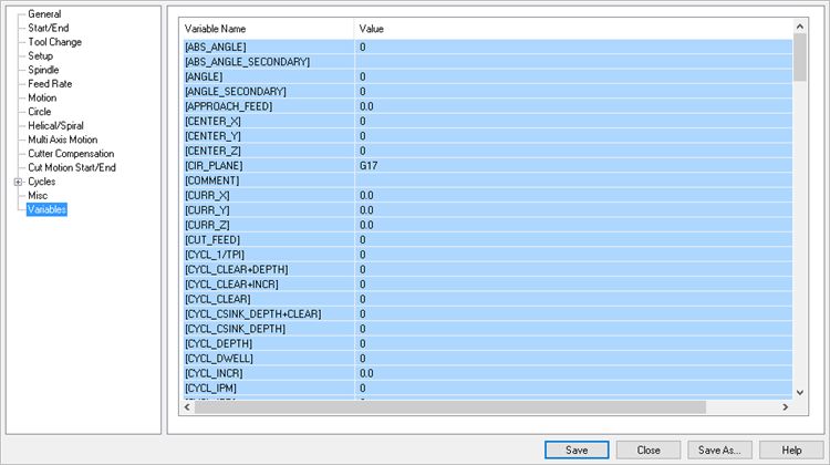
5 VisualCAM 2021 Post-Processor Generator
Quick Start
VISUALCAM2021
Prefer Printed Documentation? Check Here!
Quick Start Guides for each VisualCAD/CAM module are available in both PDF and Video format.
Refer to the following information to access these resources:
What's New
What's New in VisualCAD/CAM 2021
Watch the What's New in 2021 Webinar!
The Complete Quick Start Video Play List
Here is a link to the complete 2021 Video Play List
How to Access the Quick Start Guide Documents
To help you quickly get started in working with each module, select one of the Help
buttons located on the VisualCAD/CAM Learning Resources dialog.
You will find:
· Quick Start Guides
· What's New documents
· Online Help links
The Quick Start Guides will help you step through an example tutorial which will
illustrate how to use the module. To access the Learning Resources dialog:
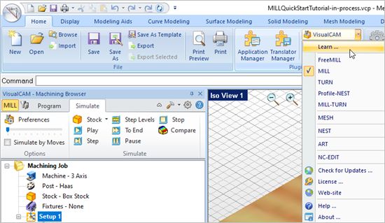
1. From the VisualCAD Home Ribbon Bar, drop down the Main menu and select Learn ...
© 2021 MecSoft Corporation
Quick Start   6

                                                  To access the Learning Resources dilog in VisualCAM

                     2. Select a document from the Learning Resources dialog to get started using the
                        module of your choice.

                             You can also select the Open Quick Start Files Folder button located at the bottom
                         of the dialog to open the Quick Start folder where the source files (start and
                         completed versions) are located.

© 2021 MecSoft Corporation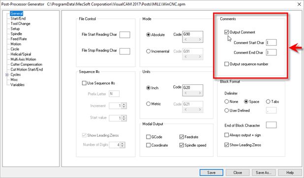
7   VisualCAM 2021 Post-Processor Generator

                                     Learning Resources Dialog

         Related Topics
         Find More Resources

                                                                 © 2021 MecSoft Corporation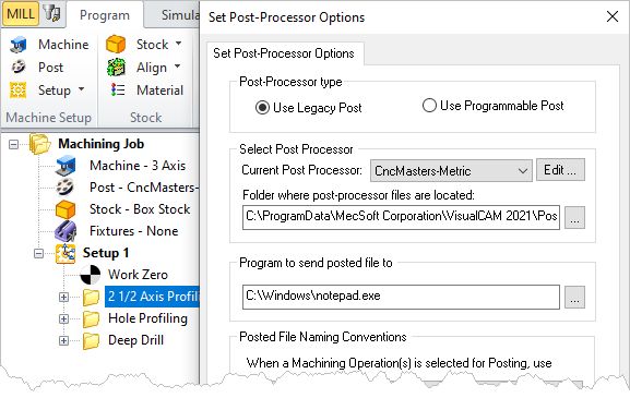
PPG Decoded Guide      8

PPG Decoded Guide
          The following guide is available Free to all Annual Maintenance Subscribers (AMS). Already an
          AMS member? Click the link below to learn how to access your free guide. Want to become an
          AMS member? Call us at (949)654-8163 to learn how you can gain access to exclusive members-
          only content including advanced user forums, training guides, self-training videos and more!

                     2020 VisualCAD/CAM Resources

                                           Get this 55-page Guide for VisualCAD/CAM!
                                           Includes self-training with emphasis on:
                                               ·    Start/End Codes
                                               ·    Spindle & Feedrate Codes
                                               ·    Arc/Circle Code Formats (I,J,K)
                                               ·    Using Cutter Compensation
                                               ·    Understanding Canned Cycle Codes and more!

© 2021 MecSoft Corporation
9 VisualCAM 2021 Post-Processor Generator
Resource Guide
Download this PDF Guide for a list of the available VisualCAD/CAM Resources.
2021 VisualCAD/CAM Resource Guide
The 2021 VisualCAD/CAM Resource Guide!
18 Pages
Lists PDF downloads and Online resources including Quick Start
Guides, Reference Guides, Exercise Guides, Tutorials and
More.
Click Here to download this Free guide!
© 2021 MecSoft CorporationGood Things to Know 10
Good Things to Know
Here is a list of things you should know when posting G-Code using a customized post created
from the Post-Processor Generator in VisualCAD/CAM.
Algebraic Expressions when Posting
The Post Process Generator now supports Algebraic Expressions in all input fields.
Here are some guidelines for using expressions:
1. Each expression should be placed in ‘E{’, ‘E}’ tags.
2. In expression can be used next operations: -,+,/,*,^
3. Negative values should be placed in parentheses '( )’
4. Expression parts can be placed in parentheses '( )’
5. Floating point numbers should be delimited by point symbol, use 0.xx in case of
fractional numbers
6. Expressions can contain spaces in any place, spaces will be removed while
parsing
7. Numbers in [-0.9; 0.9] can be written as [-.9; .9]
Examples:
· E{ ([SOME_VAR1]/2 + ([SOME_VAR2]*(-3.2)) )^3 E}
· E{[SOME_VAR1] + .3 E} SOME_TEXT E{ [SOME_VAR1] *(-1) E}
Posting Drill Cycles & Indexed Machining
Drill cycles will be converted to simulated cycles (i.e., using linear motions) if the setup
the drill cycles appear in is not aligned with the machine Z axis. This is done only when
the machine has a head configuration defined and Output all coordinates in local Setup
Coordinate System is not checked. See Machine Tool Setup for more information.
Posting Cutter Compensation (G40, G41, G42)
All toolpaths except engraving are automatically compensated for the tool geometry.
Cutter compensation is used typically to compensate for the difference in the
dimensions of the actual cutter used in machining and the cutter used for programming
in VisualCAD/CAM. For example, if the cutter used in programming is 0.25 inches and
due to tool wear the actual cutter is only 0.24 inches in size, you can compensate for this
at the controller rather than having to re-program the operation in VisualCAD/CAM.
Cutter compensation is used extensively in production (high volume) machining where
the machine operator can compensate for tool wear before having to stop and replace
the tool or insert.
© 2021 MecSoft Corporation11 VisualCAM 2021 Post-Processor Generator
In order to do this the user needs to do the following:
1. Turn cutter compensation on in the operation to Auto/ON or CONTROL/ON.
2. Specify the cutter compensation value and the compensation register in the
controller (the controller needs to be capable of doing this).
3. Please make sure the post processor is configured to output cutter
compensation. This is defined under the Cutter Compensation section in the
post processor generator. Most controllers expect an X & Y motion on the same
line as cutter compensation.
Cutter Compensation Left
[SEQ_PRECHAR][SEQNUM] G41 [G_CODE] X[NEXT_NONMDL_X] Y[NEXT_NONMDL_Y]
D[TOOL_CUTCOM_REG]
Cutter Compensation Right
[SEQ_PRECHAR][SEQNUM] G42 [G_CODE] X[NEXT_NONMDL_X] Y[NEXT_NONMDL_Y]
D[TOOL_CUTCOM_REG]
Cutter Compensation Off
[SEQ_PRECHAR][SEQNUM] G40
A few things to watch out for:
1. Cutter compensation makes sense only in 2-1/2 axis operations. If you are using
roughing (pocketing & facing) the compensation will be turned on only in the
final passes.
2. Make sure you are using Climb or Conventional cut traversal in any of the
methods that you want to turn compensation on.
© 2021 MecSoft CorporationGood Things to Know 12
3. Make sure you have a linear motion for the controller to turn on the
compensation for. If your first motion is an arc the controller will not be able to
turn on the compensation. Thus, in 2-1/2 axis profiling, make sure there is a
linear entry motion for the controller to be able to turn compensation on & linear
exit to turn off compensation.
If you are looking to compensate for the full tool diameter, set Stock = -0.125 under the
cut parameters tab. (0.125 being the radius of the tool). This would generate the toolpath
ON the curve. This would invalidate the simulation as the tool tip stays on the drive
geometry.
Note: The Cutcom Register is set under the Create/Select Tool definition dialog.
Posting a Tool Change Point
© 2021 MecSoft Corporation13 VisualCAM 2021 Post-Processor Generator
Implementing a Tool Change Point can be useful. For example in 2 and 3 Axis, you may
want to change tools manually between operations (i.e., your CNC machine does not
have an automatic tool changer). Also in 4 Axis you may want to ensure the tool is
moved to a save location prior to a table rotation. To output a Tool Change Point to your
posted g-code files, please do the following:
For 2 and 3 Axis Output
1. From the Machine Setup dialog (Program tab > Machine > General
Parameters > Tool Change Pt), enter your required tool change point
coordinates.
2. For the sample code (shown at the end of this section) we entered the
following values in the Machine Setup dialog:
X: -4, Y: 0 Z: 0
3. Edit your post processor by selecting Program tab > Post > Edit.
© 2021 MecSoft CorporationGood Things to Know 14
4. From the Post Process Generator dialog, select the Tool Change section
from the left side of the dialog.
5. In the Tool Change Macro block section, replace the first line of text
with the following two lines of text at the top of the macro.
These two lines of text should precede the line that includes
T[TOOL_NUM] as shown in the examples below.
[SEQ_PRECHAR][SEQNUM][DELIMITER]G0 Z[TOOL_CHG_PT_Z]
[SEQ_PRECHAR][SEQNUM][DELIMITER]G0 X[TOOL_CHG_PT_X] Y[TOOL_CHG_PT_Y]
[SEQ_PRECHAR][SEQNUM][DELIMITER]T[TOOL_NUM]
...
...
6. If your controller expects to see an optional stop call BEFORE each tool
change, you can add another line like below:
© 2021 MecSoft Corporation15 VisualCAM 2021 Post-Processor Generator
[SEQ_PRECHAR][SEQNUM][DELIMITER]G0 Z[TOOL_CHG_PT_Z]
[SEQ_PRECHAR][SEQNUM][DELIMITER]G0 X[TOOL_CHG_PT_X] Y[TOOL_CHG_PT_Y]
[SEQ_PRECHAR][SEQNUM][DELIMITER]M01
[SEQ_PRECHAR][SEQNUM][DELIMITER]T[TOOL_NUM]
...
...
7. From the Post Process Generator dialog, pick Save As.
8. Enter a unique name for your post file (*.spm) for testing and pick Save.
9. From the Set Post-Processor Options dialog, select the revised post
from the Current Post Processor list.
10. Note: If you do not see your revised post in the list, select the "..."
button to the right of the "Folder where post-processor file are located"
and select the folder where you saved your revised post file to (see
Step 7 above) and pick OK.
11. You should now see your revised post in the list. Select it and pick OK.
12. Post a sample toolpath using the revised post.
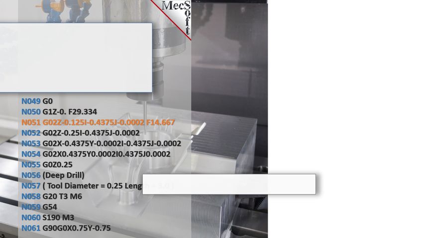
13. Review the g-code test file and locate the first tool change lines of
code.
14. Your sample test should look something like this depending on your
post (based on the tool change point we used in Step 2 above). Note
the tool change coordinates in blue:
...
...
N66 ;2 1/2 Axi s Profi l i ng
N68 G0 Z0.
N70 G0 X-4. Y0.
N72 T1 M06
© 2021 MecSoft CorporationGood Things to Know 16
...
...
15. That's it!
For 4 Axis Output
1. From the Program tab select 4 Axis.
2. From the 4 Axis menu select 4 Axis Options.
3. From the 4 Axis Operation Options dialog check the box to Always
retract tool to Tool Change Point before each Table Rotate Operation.
4. Now from the Program tab select Machine and then Manual Definition.
5. For the Machine Type select 4 Axis.
6. Under General Parameters, enter the X, Y and Z coordinate values for
the Tool Change Point.
7. Then check the box to Output all coordinates in local Setup Coordinate
System and then pick OK to close the dialog.
© 2021 MecSoft Corporation17 VisualCAM 2021 Post-Processor Generator
8. Post the 4 Axis toolpath operation and verify that the Tool Change Point
is being posted before the table rotation angle similar to this:
...
...
(Setup 2)
N6263 Z10.
N6264 X0.Y0.
(Hori zonta l Roughi ng)
N6265 A180.F300.
...
...
Posting Tool Comments
You can add comments associated with a Tool. These Comments are saved with the Tool
in your Tool Library. They are also posted to your g-code when the tool is used.
Here are the steps to add Comments to a Tool:
1. Edit the Tool using the Create/Select Tool dialog.
2. Select the Properties tab on the right.
3. Add text to the Comments window.
© 2021 MecSoft CorporationGood Things to Know 18
4. Make sure Comments are enabled in your post.
A. Click on Post (Set Post-Processor Options), then click Edit.
B. From the Post Processor Generator dialog, select the General tab from
the left.
© 2021 MecSoft Corporation19 VisualCAM 2021 Post-Processor Generator
C. Check the box to Output Comments. You can also change the start and
end characters to use.
D. Then pick Save or Save As.
5. Now post your operations and see your comments:
...
...
G1 X0.5301 Y-0.7171 Z0.7480
G3 X0.7801 Y-0.4671 I0.0000 J0.2500 F2.6
G1 X0.7801 Y-0.2171 Z0.7480 F6.9
G0 Z0.9843
G0 X0.7801 Y-0.2171
(2 1/2 Axis Profiling)
(My Tool Comments Here!)
S18000
G0 Z0.9843
G0 X0.5301 Y-0.7097
G1 X0.5301 Y-0.7097 Z0.7480 F6.9
G1 X0.5873 Y-0.7097 Z0.7480 F3.4
G1 X0.5873 Y-0.6345 Z0.7480
G1 X0.4729 Y-0.6345 Z0.7480
...
...
6. If you want to post g-codes instead of comments, just place a $ character prior to
the comment in the Create/Select Tools dialog. Adding $ as prefix will skip the
comment start & end characters in the posted code.
© 2021 MecSoft CorporationGood Things to Know 20
...
...
G1 X0.4655 Y-0.7171 Z0.7480
G1 X0.5301 Y-0.7171 Z0.7480
G3 X0.7801 Y-0.4671 I0.0000 J0.2500 F2.6
G1 X0.7801 Y-0.2171 Z0.7480 F6.9
G0 Z0.9843
G0 X0.7801 Y-0.2171
(2 1/2 Axis Profiling)
My g-code Here!
S18000
G0 Z0.9843
G0 X0.5301 Y-0.7097
G1 X0.5301 Y-0.7097 Z0.7480 F6.9
G1 X0.5873 Y-0.7097 Z0.7480 F3.4
G1 X0.5873 Y-0.6345 Z0.7480
...
...
Related Topics
Post Processor File Browser
Main Editor
Variable List Dialog
© 2021 MecSoft Corporation21 VisualCAM 2021 Post-Processor Generator
Use Legacy Post
Select this option from the Post-Processor Options dialog to use your "Legacy Post"
when posting toolpath operations. "Legacy Post" refers to your post definition (*.spm)
file you used prior to version 2021. This option also lists the over 300 existing post-processors.
See Current Post Processor below.
Dialog Box: Set Post-Processor Options
Dialog Box: Set Post-Processor Options
© 2021 MecSoft CorporationUse Legacy Post 22
6.1 Dialogs
6.1.1 Post Processor File Browser
The dialog shown below is used to select the post processor file to be edited. (SPM File). The
name and location of the post processor file can be either entered in the edit box provided, or can
be selected using the browse button. The user can double click on the required SPM File to invoke
the Editor.
Dialog Box: Post Processor File Browser
Dialog Box: Post Processor File Browser
Related Topics
Introduction
Post Processor Editor
Variable List Dialog
© 2021 MecSoft Corporation23 VisualCAM 2021 Post-Processor Generator
6.1.2 PPG Editor
The VisualCAD/CAM Post-Processor Generator (PPG) Editor is shown below. This Editor is divided
into sections (listed on the left) allowing you to define each block type. Refer to the list of
sections below.
Dialog Box: Post Processor Generator: Editor
Dialog Box: Post Processor Generator: Editor
PPG Editor Sections
· General
This folder helps you set up file information, G-Code format, mode and the units
of operation.
· Start End
Start and End code specifier.
· Tool Change
Load and Tool Change Macro specifier.
· Setup
Setup change and Rotate Table Setup specifier.
· Spindle
Spindle code specifier.
· Feed Rate
Feed Rate specifier.
© 2021 MecSoft CorporationUse Legacy Post 24
· Motion
Motion block specifier
· Circle
Circle block specifier.
· Helical/Spiral
Helical and Spiral motion block specifier.
· Multi Axis Motion
Multi Axis Motion specifier.
· Cutter Compensation
Motion blocks for Cutter Compensation Right, Left and Off.
· Cut Motion Start/End
Cut Motion Start and End macro blocks.
· Cycles
Cycle G-Code and format specifier.
· Miscellaneous
Coolant and Compensation code specifier
· Variables
Lists variables and their values used in post-processing
Related Topics
Introduction
Post Processor File Browser
Variable List Dialog
6.1.3 Variable List Dialog
The Variable List dialog shown below can be invoked by pressing the right mouse button from
within edit boxes that are used in setting up startup and termination code for a post-processor.
This dialog can be used to add variables to the active edit box for macros.
Dialog Box: Variable List
© 2021 MecSoft Corporation25 VisualCAM 2021 Post-Processor Generator
Dialog Box: Variable List
Related Topics
Post Processor File Browser
Post Processor Editor
Variables List
6.2 PPG Editor
6.2.1 General
The General section allows you to define the general behavior of the post-processor output. Each
editable parameter is described below.
PPG Editor: General
© 2021 MecSoft CorporationUse Legacy Post 26
PPG Editor: General
File Control
This section allows you to set the default extension of the output file.
· File Start Reading Char
The user can also set up an optional File Start character. This file start
character will be the first character written to the output file.
· File Stop Reading Char
Similarly the file end character will be the last character written to the output
file. Most standard controllers look for a percent sign (%) as this last
character.
Mode
Coordinate values can be set to be either Absolute or Incremental. In the Absolute
mode, coordinate values (X, Y, Z, I, J, K) are output as absolute values. In the
Incremental mode, coordinate values are output as incremental values.
Comments
This section defines the general format of commentary blocks.
· Output Comment: Set parameter to output comments
· Comment Start Char: Comment start character
· Comment End Char: Comment end character
· Output Sequence Number: Toggle sequence number for comments
© 2021 MecSoft Corporation27 VisualCAM 2021 Post-Processor Generator
If you want the comments to be output just as it is without the Start Character and
the End Character, then in VisualCAD/CAM, when you are inserting a comment, type
in a $ sign in front of it, like:
$ Comment
Sequence #s
This section allows you to control the format of sequence numbers to the output file.
This option is available for all G-code lines except Tool change Macro and Start and
End Code.
· Use Sequence #s
Sequence number output can be turned on or off.
· Prefix Letter
When on, a prefix letter can optionally be added at the beginning of every
sequence number.
· Increment
Sequence numbers can also be output in increments rather than
sequentially. This increment value can be specified here.
· Start Value
This specifies the starting value for the sequence numbers.
· Show Leading Zeros
In addition the number of digits output as well as presence/absence of
leading zeros in the sequence numbers can be controlled.
Units
This tells the post-processor the units of the output file by outputting a units code
that can be defined here. Output units can either be in the English system (inches) or
in the Metric system (mm).
· Inch
Sets the units to Inches and post the code G20 by default. This code can be
changed if desired.
· Metric
Sets the units to Millimeters and post the code G21 by default. This code can
be changed if desired.
Block Format
This section defines the general format of all output blocks. Each of the options is
described below.
· Delimiter:
This is the delimiter used between G-codes.
Example where delimiter is set to [D]: G01[D]X1.0[D]Y2.0[D]Z3.0[D]
© 2021 MecSoft CorporationUse Legacy Post 28
S3000M03[D]F20
None: No delimiter is posted in the output.
Space: A space character is output as the delimiter
Tab: A tab character is output as the delimiter
User Defined: Select this option and then enter the delimiter character to
use.
· End of Block Character: End of block character to output
· Always output +sign: Outputs a ‘+’ (no quote marks included) for positive
values.
· Show Leading Zeros: Check this box to include leading zeros in the posted
code. Example (G01 X+1.0 Y+1.0 Z+1.0)
Modal Output
The Post processor generator allows the following parameters to be set as modal or
non-modal. The modal output setting will output the value of a variable only if it is
different from the value that was last output.
· Gcode: G-Code modal option sample
· Coordinate: Coordinates modal option sample
· Feedrate: Feed Rate modal option sample
· Spindle speed: Spindle Speed modal option sample
An example of non-modal data is shown below. The repeated values are shown in
colored text.
S1000M03
G00 X1.0 Y2.0 Z0.0 F10
S2000M03
G01 X1.0 Y2.0 Z3.0 F20
G01 X1.0 Y3.0 Z3.0 F20
S2000M03
Related Topics
Other PPG Editor Sections:
Start/End
Tool Change
Setup
Spindle
Feed Rate
Motion
© 2021 MecSoft Corporation29 VisualCAM 2021 Post-Processor Generator
Circle
Helical/Spiral Cycles
Multi Axis Motion
Cutter Compensation
Cut Motion Start/End
Cycles
Miscellaneous
Variables
6.2.2 StartEnd
This tab is used to set the Start and End G-Codes.
PPG Editor: Start/End
PPG Editor: Start/End
Startup Code
First macro output in the generated NC file.
Example:
[START_CHAR]
O[PARTNUM]
[SEQ_PRECHAR][SEQNUM]G40G49G80
End Code
© 2021 MecSoft CorporationUse Legacy Post 30
Last macro output in the generated NC file.
Example:
[SEQ_PRECHAR][SEQNUM]M30
[STOP_CHAR]
Related Topics
How to edit macros
Other PPG Editor Sections:
General
Tool Change
Setup
Spindle
Feed Rate
Motion
Circle
Helical/Spiral Cycles
Multi Axis Motion
Cutter Compensation
Cut Motion Start/End
Cycles
Miscellaneous
Variables
6.2.3 Tool Change
This tab is used to set the Load Tool and Tool Change macros.
PPG Editor: Tool Change
© 2021 MecSoft Corporation31 VisualCAM 2021 Post-Processor Generator
PPG Editor: Tool Change
Use 2 digit format for Tool number and registers
Check this box to use 2-digit format for Tool Numbers and Tool Registers (i.e., T01)
Output tool list as comments at start of program
Check this box to include the tool list as a comment at the start of the program.
Example:
%
O0
N1G40G49G80
( BEGIN TOOL LIST )
( TOOL 1 - FLATMILL- 1/2 INCH - DESC: 0.5000 DIA, 2 FLUTE, CARBIDE MAT )
( TOOL 2 - BALLMILL- 1/4 INCH - DESC: 0.2500 DIA, 2 FLUTE, CARBIDE MAT )
( ENDOF TOOL LIST )
(Setup 1)
(Horizontal Roughing)
N2(Tool Diameter = 0.5 Length = 4.0 )
N3G54
...
...
...
First Load Tool Marco
© 2021 MecSoft CorporationUse Legacy Post 32
Macro for the first load tool command.
Example:
[SEQ_PRECHAR][SEQNUM](Tool Diameter = [TOOL_DIA] Length = [TOOL_LENGTH] )
[SEQ_PRECHAR][SEQNUM]G54
[SEQ_PRECHAR][SEQNUM][OUTPUT_UNITS_CODE]T[TOOL_NUM]M6
[SEQ_PRECHAR][SEQNUM][SPINDLE_BLK]
[SEQ_PRECHAR][SEQNUM][OUTPUT_MODE_CODE][G_CODE]X[NEXT_NONMDL_X]
Y[NEXT_NONMDL_Y]
[SEQ_PRECHAR][SEQNUM]G43Z[NEXT_NONMDL_Z]H[TOOL_NUM]
Tool Change Macro
Macro for tool change command. (Not including the first load tool.)
Example:
[SEQ_PRECHAR][SEQNUM](Tool Diameter = [TOOL_DIA] Length = [TOOL_LENGTH] )
[SEQ_PRECHAR][SEQNUM][OUTPUT_UNITS_CODE]T[TOOL_NUM]M6
[SEQ_PRECHAR][SEQNUM]G54
[SEQ_PRECHAR][SEQNUM][SPINDLE_BLK]
[SEQ_PRECHAR][SEQNUM][OUTPUT_MODE_CODE][G_CODE]X[NEXT_NONMDL_X]
Y[NEXT_NONMDL_Y]
[SEQ_PRECHAR][SEQNUM]G43Z[NEXT_NONMDL_Z]H[TOOL_NUM]
Related Topics
How to edit macros
Other PPG Editor Sections:
General
Start/End
Setup
Spindle
Feed Rate
Motion
Circle
Helical/Spiral Cycles
Multi Axis Motion
Cutter Compensation
Cut Motion Start/End
Cycles
© 2021 MecSoft Corporation33 VisualCAM 2021 Post-Processor Generator
Miscellaneous
Variables
6.2.4 Setup
PPG Editor: Setup
PPG Editor: Setup
Setup 0 (Coordinate System Change) Macro
Macro to execute before every Setup change.
Example:
[LINEAR][NEXT_X][NEXT_Y][NEXT_Z][ROTATION_AXIS][ROTATION_DIR][ANGLE]
[FEEDRATE_CODE][ROTATION_FEEDVALUE]
Setup 1 (Rotate Table) Macro
Macro to execute before every Rotate Table Setup change.
Example:
[ROTATION_AXIS][ROTATION_DIR][ANGLE][FEEDRATE_CODE][ROTATION_FEEDVALUE]
Related Topics
Other PPG Editor Sections:
General
Start/End
© 2021 MecSoft CorporationUse Legacy Post 34
Tool Change
Spindle
Feed Rate
Motion
Circle
Helical/Spiral Cycles
Multi Axis Motion
Cutter Compensation
Cut Motion Start/End
Cycles
Miscellaneous
Variables
6.2.5 Spindle
This tab is used to set parameters for controlling the spindle.
PPG Editor: Spindle
PPG Editor: Spindle
Block Format
Sets the spindle block format.
© 2021 MecSoft Corporation35 VisualCAM 2021 Post-Processor Generator
· Spindle Code: Register used for the feed rate value.
· Spindle Direction: Specify the direction code for the spindle
Clockwise Rotation Code: Clockwise spindle code
C-Clockwise Rotation Code: Counter clockwise spindle code
Spindle Off Code: Spindle off code
· Spindle Mode:
Constant Surface Speed:
Constant Rotation Speed:
· Spindle Block Format: Defines the block format for the spindle. Example:
S[SPINDLE_SPD][SPINDLE_ARC]
· Default: Reset all values in this section to their system defaults.
· Sample output: This field displays sample output of the spindle block. It is a
non-editable field.
Spindle RPM
· High Value: Maximum spindle value. The spindle RPM is capped to this high
value.
· Low Value: Minimum spindle value. The spindle RPM is capped to this low
value.
· Scale Factor: Scale factor of Spindle value.
· # of Decimal Places: Number of digits output after the decimal point
· Show Trailing Zeros: Show trailing zeros when # of Decimal Places is set to a
value greater than zero.
Related Topics
Other PPG Editor Sections:
General
Start/End
Tool Change
Setup
Feed Rate
Motion
Circle
Helical/Spiral Cycles
© 2021 MecSoft CorporationUse Legacy Post 36
Multi Axis Motion
Cutter Compensation
Cut Motion Start/End
Cycles
Miscellaneous
Variables
6.2.6 Feed Rate
This tab sets the feeds and speeds parameters
PPG Editor: Feed Rate
PPG Editor: Feed Rate
Block Format
Characters for the feed rate block:
· Feed Rate Code: Register used for the feed rate value
· Add after Next Motion Code:
· Feed Rate Modes
Units/Min Code: Typically a G94
Unites/Rev Code: Typically a G95
· Inverse Time Feed Rate
© 2021 MecSoft Corporation37 VisualCAM 2021 Post-Processor Generator
When Output inverse time feedrate for 4 & 5 Axis motions is
selected the On Code is output at the start of the operation and
Off Code at the end.
You turn on the Inverse Time Feedrate using a checkbox in the
Post/Feedrate tab. You can set up the code for On and Off in the
same tab. Once this is set, then all 4 and 5 axis motions will be
processed with this feedrate being output.
The way the feedrate is computed is as follows:
First the distance traveled by the tool is computed for each
move = dist
Then the time taken for traversing the move is computed thus:
timeForTravel = dist / cutFeedRate;
Then the inverse time feedrate is = 1.0/timeForTravel;
And it is output for each move if different from previous move.
On Code: G93
Off Code: G94
· Block Format: Format for the feed rate block
· Default: Reset all values in this section to their system defaults.
· Sample Output: Sample output displays sample code of the feed
rate. It is a non-editable field.
Feed Rate values
Parameters for the adjustment of feed rate value:
· High Value: Maximum Feed rate value.
· Low Value: Minimum Feed rate value.
· Scale Factor: Scale factor of Feed rate value.
· # of Decimal Places: Number of digits output after the decimal point.
· Z Feed Rate Scale Factor: Feed rate scale factor for Z Feed Rate (use
[ZFEEDRATE] variable to get the Z feed rate)
· Show Trailing Zeros: Show trailing zeros when # of Decimal Places is set to a
value greater than zero.
Angular Rate values
· Scale Factor: Enter the scale factor for angular feed rate values.
· # of Decimal Places: Number of digits output after the decimal point
© 2021 MecSoft CorporationUse Legacy Post 38
· Show Trailing Zeros: Show trailing zeros when # of Decimal Places is set to a
value greater than zero.
Related Topics
Other PPG Editor Sections:
General
Start/End
Tool Change
Setup
Spindle
Motion
Circle
Helical/Spiral Cycles
Multi Axis Motion
Cutter Compensation
Cut Motion Start/End
Cycles
Miscellaneous
Variables
6.2.7 Motion
This tab is used to define the linear motion outputs of a post-processor.
PPG Editor: Motion
© 2021 MecSoft Corporation39 VisualCAM 2021 Post-Processor Generator
PPG Editor: Motion
Linear Motion Block
Used to define the output format for the cut motions ( e.g.: G1). The sample output
can be seen in the non-editable Sample Output field.
· G Code: Typically a G1
· Block Format: Example: [G_CODE][NEXT_X][NEXT_Y][NEXT_Z]
· Default: Reset all values in this section to their system defaults.
· Sample Output: This displays how the posted output will look.
· Output cut motion start macro before plunge motion: Checking this box will
output the cut motion start macro defined under Cut Motion Start/End
section before the plunge motion in the posted code.
Rapid Motion Block Format
Used to define the output format for the rapid motions ( e.g.: G0). The sample output
can be seen in the non-editable Sample Output field.
· G Code: Typically G0
· Block Format: Example:
[G_CODE][NEXT_Z]
[NEXT_X][NEXT_Y]
· Default: Reset all values in this section to their system defaults.
© 2021 MecSoft CorporationUse Legacy Post 40
· Sample Output: This displays how the posted output will look.
Motion Coordinates
· Scale Factor for X, Y, Z: Scale factor of the coordinate values. (Includes circles
and cycles)
· Show Trailing Zeros: Show the trailing zeros ( e.g. 5.4 is output as 5.4000)
· # of Decimal Places: Number of digits output after the decimal point
Related Topics
Other PPG Editor Sections:
General
Start/End
Tool Change
Setup
Spindle
Feed Rate
Circle
Helical/Spiral Cycles
Multi Axis Motion
Cutter Compensation
Cut Motion Start/End
Cycles
Miscellaneous
Variables
6.2.8 Circle
This tab is used to define the circle block output.
PPG Editor: Circle
© 2021 MecSoft Corporation41 VisualCAM 2021 Post-Processor Generator
PPG Editor: Circle
G Code
Arc Direction Code:
· Clockwise Arc Code: Typically G02
· C-clockwise Arc Code: Typically G03
Plane Code
The G Code for the principal planes in which the Arc motion is output.
· XY: Typically G17
· ZX: Typically G18
· YZ: Typically G19
Output Format
These options help define the output format for the circle command.
· I,J,K and Radius: Output I,J,K and Radius
· I,J,K only: Output only I,J,K.
· Radius only: Output only Radius.
· Output values only when different: Output I,J,K,R values only when different
from the previous values.
© 2021 MecSoft CorporationUse Legacy Post 42
· Use -R for CW Arcs: Prefixes -R before clockwise arc motions.
Arc Center (I,J,K)
Defines the calculation of the arc center coordinates.
· Absolute: is the absolute center
· Vector from Center to Start: is (Center - Start)
· Vector from Start to Center: is (Start - Center)
· Unsigned vector: is the unsigned distance between center and start.
Block Format
Used to specify the block format for three different planes. Use the default button to
see the default values and edit them if needed.
Sample Output
This field displays sample output of the arc motion block. This field is non-editable. It
indicates the parameters selected from the available options.
Limit Arcs to Angle
This is used to limit arcs to a certain angle. This is helpful for certain types of
controllers which cannot output arcs greater than a certain angle
Default
Reset all values in this section to their system defaults.
Related Topics
Other PPG Editor Sections:
General
Start/End
Tool Change
Setup
Spindle
Feed Rate
Motion
Helical/Spiral Cycles
Multi Axis Motion
Cutter Compensation
© 2021 MecSoft Corporation43 VisualCAM 2021 Post-Processor Generator
Cut Motion Start/End
Cycles
Miscellaneous
Variables
6.2.9 Helical/Spiral
This tab is used to define the Helix and Spiral block output. For both these cycles, the Arc Center
and the Plane Code are the same as those defined in the Circle Section. Please define those first
before defining these cycles.
PPG Editor: Helical/Spiral Cycles
PPG Editor: Helical/Spiral Cycles
Select Interpolation Type
Used to select the Interpolation type to define the parameters for the Helical Cycles
or the Spiral Cycles.
G Code
Used to define the Clockwise and the Counter Clockwise Codes for the Helical or
Spiral Cycles
Block Format
© 2021 MecSoft CorporationUse Legacy Post 44
Used to specify the block format for three different planes. Use the default button to
see the default values and edit them if needed.
Default
Reset all values in this section to their system defaults.
Sample Output
This field displays sample output of the Helical/Spiral motion block. This field is non-
editable. It indicates the parameters selected from the available options.
Related Topics
Other PPG Editor Sections:
General
Start/End
Tool Change
Setup
Spindle
Feed Rate
Motion
Circle
Multi Axis Motion
Cutter Compensation
Cut Motion Start/End
Cycles
Miscellaneous
Variables
6.2.10 Multi Axis Motion
This tab is used to set 4th Axis Motion Section parameters.
PPG Editor: Multi Axis Motion
© 2021 MecSoft Corporation45 VisualCAM 2021 Post-Processor Generator
PPG Editor: Multi Axis Motion
Block Format
Rotation Axis Code
Characters for Rotation Axis Code.
· Primary Axis: Sets the primary axis code. Typically A
· Secondary Axis: Sets the secondary axis code. Typically B
· Tertary Axis: Sets the Tertary axis code. Typically C
Rotation Direction Code (Only for Rotate Table)
Characters for Rotation Direction Code
· Clockwise Rotation: Clockwise rotation code
· Counter Clockwise Rotation: Counter Clockwise rotation code
· Ignore in continuous rotation toolpaths: Check this box to ignore
rotation direction in 4 Axis continuous rotation toolpaths.
Angle Values
Angle Value for 4th Axis Motion
· Scale Factor: Scale Factor for Angle Value (the angle is in radians, to
convert to degrees use a scale factor of 57.295779513082
· # Decimal Places: No of Decimal Places
· Trailing Zeros: Number of Trailing Zeros after Decimal places
© 2021 MecSoft CorporationUse Legacy Post 46
Motion Block
Motion Code for 4th Axis Motion
· Block Format: Helps to define the output format for the 4th Axis motion
code.
· Sample Output: Sample output displays sample code of the 4th Axis motion.
It is a non-editable field.
· Default: Reset all values in this section to their system defaults.
Rapid Block
Rapid Code for 4th Axis Motion
· Block Format: Helps to define the output format for the 4th Axis rapid code
· Sample Output: Sample output displays sample code of the 4th Axis rapids. It
is a non-editable field.
· Default: Reset all values in this section to their system defaults.
Related Topics
Other PPG Editor Sections:
General
Start/End
Tool Change
Setup
Spindle
Feed Rate
Motion
Circle
Helical/Spiral Cycles
Cutter Compensation
Cut Motion Start/End
Cycles
Miscellaneous
Variables
© 2021 MecSoft Corporation47 VisualCAM 2021 Post-Processor Generator
6.2.11 Cutter Compensation
PPG Editor: Cutter Compensation
PPG Editor: Cutter Compensation
Cutter Compensation Left
Macro used to define the output when the cutter compensation left is detected in
the output
Cutter Compensation Right
Macro used to define the output when the cutter compensation right is detected in
the output
Cutter Compensation Off
Macro used to define the output when the cutter compensation cancel (off) is
detected in the output
Related Topics
Other PPG Editor Sections:
General
Start/End
Tool Change
Setup
© 2021 MecSoft CorporationUse Legacy Post 48
Spindle
Feed Rate
Motion
Circle
Helical/Spiral Cycles
Multi Axis Motion
Cut Motion Start/End
Cycles
Miscellaneous
Variables
6.2.12 Cut Motion Start/End
PPG Editor: Cut Motion Start/End
PPG Editor: Cut Motion Start/End
Allows you to define Start and End cut motion codes.
Note: You can have the Cut Motion Start Up Code posted before plunge motions by
checking the box (Output cut motion start macro before plunge motion) on the Motion
section of this dialog.
Related Topics
© 2021 MecSoft Corporation49 VisualCAM 2021 Post-Processor Generator
Other PPG Editor Sections:
General
Start/End
Tool Change
Setup
Spindle
Feed Rate
Motion
Circle
Helical/Spiral Cycles
Multi Axis Motion
Cutter Compensation
Cycles
Miscellaneous
Variables
6.2.13 Cycles
This tab is to set the cycle parameters in the VisualCAD/CAM Post-Processor.
PPG Editor: Cycles
© 2021 MecSoft CorporationUse Legacy Post 50
PPG Editor: Cycles
Cycle G-Code
Macros for the cycle commands. It represents the selected G-code value that defines
each specific cycle. This value is displayed in the edit box below all the available
options. It can be changed if required.
Cycle Code
The following Cycles are supported:
· Cycle Off (G80)
· Standard Drill (G81)
· Standard Drill with Dwell On (G82)
· Deep (G83)
· Break Chip (G87)
· Counter Sink (G82)
· Tap (Clockwise) (G84)
· Tap (C-Clockwise) (G84)
· Peck Tapping (Clockwise) (G84)
· Peck Tapping (C-Clockwise) (G84)
· Rigid Tap (Clockwise) (T00)
· Rigid Tap (C-Clockwise) (T01)
· Bore (Drag) Dwell Off (G85)
· Bore (Drag) Dwell On (G89)
· Bore (No Drag) Dwell Off Orient On (G76)
· Bore (No Drag) Dwell On Orient On (G76)
© 2021 MecSoft Corporation51 VisualCAM 2021 Post-Processor Generator
· Bore (No Drag) Dwell Off Orient Off (G86)
· Bore (No Drag) Dwell On Orient Off (G86)
· Bore (Reverse) Dwell Off (G87)
· Bore (Manual) Dwell On (G88)
· Bore (Reverse) Dwell Off (G77)
· Bore (Reverse) Dwell On (G77)
· User Defined Drill Cycle 1
· User Defined Drill Cycle 2
· User Defined Drill Cycle 3
· User Defined Drill Cycle 4
· User Defined Tap Cycle 1
· User Defined Tap Cycle 2
· User Defined Tap Cycle 3
· User Defined Tap Cycle 4
· User Defined Bore Cycle 1
· User Defined Bore Cycle 2
· User Defined Reverse Bore Cycle 1
· User Defined Reverse Bore Cycle 2
· Turn Thread Cycle Automatic
· Turn Thread Cycle Box Cycle
· Turn Thread Cycle Single Block
· Machine Control Cycle 1
· Machine Control Cycle 2
· Machine Control Cycle 3
· Machine Control Cycle 4
Optimize Cycle Options
Optimize Cycle output will define the cycle format only once and will output the X,Y
values for all the other holes. This will result in significant reduction in the file size
for output.
· Optimize Cycle Output: Enables the optimized cycle options.
· Cycle Coordinate Block: Specific cycle block variables to use.
Dwell Options
· Scale Factor for Dwell: Sets the scale factor for dwell output.
· # of Decimal Places: Sets the number of decimal places for output.
Thread First Depth Options
· Scale Factor: Sets the scale factor for the first thread depth.
· # of Decimal Places: Sets the number of decimal places for output.
© 2021 MecSoft CorporationUse Legacy Post 52
Related Topics
How to edit macros
Other PPG Editor Sections:
General
Start/End
Tool Change
Setup
Spindle
Feed Rate
Motion
Circle
Helical/Spiral Cycles
Multi Axis Motion
Cutter Compensation
Cut Motion Start/End
Miscellaneous
Variables
6.2.14 Miscellaneous
This tabbed dialog is used to set miscellaneous parameters. The various miscellaneous
parameters are shown in the dialog.
PPG Editor: Miscellaneous
© 2021 MecSoft Corporation53 VisualCAM 2021 Post-Processor Generator
PPG Editor: Miscellaneous
Coolant Codes
· Coolant Off: Coolant Off code
· Coolant Mist: Coolant Mist code
· Coolant Tap: Coolant Tap code
· Coolant On: Coolant On code
· Coolant Flood: Coolant Flood code
· Coolant Thru: Coolant Thru code
Compensation
· Compensation Off: (This is not editable - reserved for future releases)
· Compensation Left: (This is not editable - reserved for future releases)
· Compensation Right: (This is not editable - reserved for future releases)
· Compensation Length: (This is not editable - reserved for future releases)
Work (Fixture) Offsets
· Work (Fixture) Offsets: Sets the work offset prefix code. Typically G. You
can enable the output of the work offset code by selecting Output Work
Offset from the Work Zero dialog and entering the offset code. For example,
enabling and entering 54 in the Work Zero dialog activates this portion of the
post and prefixes the code with this value. Example: G54.
© 2021 MecSoft CorporationUse Legacy Post 54
Related Topics
Other PPG Editor Sections:
General
Start/End
Tool Change
Setup
Spindle
Feed Rate
Motion
Circle
Helical/Spiral Cycles
Multi Axis Motion
Cutter Compensation
Cut Motion Start/End
Cycles
Variables
6.2.15 Variables
This tab lists all the variables used in the macros in the VisualCAD/CAM Post Processor.
PPG Editor: Variables
© 2021 MecSoft Corporation55 VisualCAM 2021 Post-Processor Generator
PPG Editor: Variables
Variables
The variables that can be used are listed in the table below.
The variables that start with “CYCL_” are used only for the cycles commands.
Variable Comments
[ABS_ANGLE]
[ABS_ANGLE_SECONDARY]
[ANGLE]
[ANGLE_SECONDARY]
[APPROACH_FEED]
[CENTER_X]
[CENTER_Y]
[CENTER_Z]
[CIR_PLANE]
[COMMENT] Output comments .
[CURR_X] The X coordi na te of current poi nt.
[CURR_X_WCS] The X coordi na te of current poi nt i n
Worl d Coordi na tes
© 2021 MecSoft CorporationUse Legacy Post 56
[CURR_Y] The Y coordi na te of current poi nt.
[CURR_Y_WCS] The Y coordi na te of current poi nt i n
Worl d Coordi na tes
[CURR_Z] The Z coordi na te of current poi nt.
[CURR_Z_WCS] The Z coordi na te of current poi nt i n
Worl d Coordi na tes
[CUT_FEED]
[CYCL_1/TPI] 1/TPI (onl y for TAP cycl e)
[CYCL_CLEAR+DEPTH] Dri l l Depth + Cl ea r. (onl y for cycl es
except C-SINK)
[CYCL_CLEAR+INCR]
[CYCL_CLEAR] Cl ea ra nce. (onl y for cycl es )
[CYCL_CSINK_DEPTH+CLEAR] Dri l l Depth + Cl ea r. (onl y for C-SINK
cycl e)
[CYCL_CSINK_DEPTH] Dri l l Depth. (onl y for C-Si nk cycl e)
[CYCL_DEPTH] Dri l l Depth. (onl y for cycl es except C-
SINK)
[CYCL_DWELL] Dwel l . (onl y for cycl es )
[CYCL_INCR] Step Increment. (onl y for cycl es )
[CYCL_IPM] IPM. (onl y for cycl es except TAP)
[CYCL_IPR] IPR. (onl y for TAP cycl e)
[CYCL_NEG_CLEAR+DEPTH] -( Dri l l Depth + Cl ea r). (onl y for cycl es
except C-SINK)
[CYCLE_NUM_STEPS]
[CYCL_ORIENT] Ori ent. (onl y for cycl es )
[CYCL_SCALED_DWELL] Dwel l * Sca l e Fa ctor (onl y for cycl es )
[CYCL_TPI]
[CYCL_Z+CLEAR] Next Z + Cl ea ra nce. (onl y for cycl es )
[CYCL_Z+DEPTH+CLEAR] Next Z + Depth + Cl ea ra nce. (onl y for
cycl es )
[CYCL_Z+DEPTH] Next Z + Depth. (onl y for cycl es )
[CYCL_Z-DEPTH] Next Z - Depth. (onl y for cycl es )
[DELIMITER] Del i mi ter defi ni ti on.
© 2021 MecSoft Corporation57 VisualCAM 2021 Post-Processor Generator
[DEPART_FEED] Outputs the Depa rture feedra te va l ue
for the currentl y opera ti on.
[ENGAGE_FEED] Outputs the Enga ge feedra te va l ue for
the currentl y opera ti on.
[EOB] The end of bl ock cha ra cter.
[EXTRUSION]
[EXTRUSION_BLK]
[EXTRUSION_CODE]
[FEEDRATE] FeedRa te Va l ue.
[FEEDRATE_BLK] FeedRa te Bl ock.
[FEEDRATE_CODE] Outputs the Feedra te code
[FEEDRATE_UNITS_CODE] Outputs the Feedra te Uni ts code
[FIRST_TOOL_NUM]
[G_CODE] The next G-Code. Thi s i s tra ns l a ted to
l i nea r, ra pi d, a rc or cycl e G-Code.
[HELIX_ANGLE]
[HELIX_CCW_ARC]
[HELIX_CW_ARC]
[HELIX_LEAD]
[HELIX_NUM_REV]
[HELIX_RADIUS]
[HELIX_TOTAL_DEPTH]
[INPUTFILE_NAME]
[INPUTFILE_NAME_LONG]
[INV_TIME_FEEDRATE_OFF]
[INV_TIME_FEEDRATE_ON]
[LINEAR] The l i nea r moti on code.
[MAXZ]
[MINZ]
© 2021 MecSoft CorporationUse Legacy Post 58
[MOP_NAME]
[NEXT_ABS_X_WCS] The next a bs ol ute X coordi na te poi nt
i n Worl d Coordi na tes .
[NEXT_ABS_Y_WCS] The next a bs ol ute Y coordi na te poi nt
i n Worl d Coordi na tes .
[NEXT_ABS_Z_WCS] The next a bs ol ute Z coordi na te poi nt
i n Worl d Coordi na tes .
[NEXT_I]
[NEXT_J]
[NEXT_K]
[NEXT_NONMDL_E]
[NEXT_NONMDL_I]
[NEXT_NONMDL_J]
[NEXT_NONMDL_K]
[NEXT_NONMDL_L]
[NEXT_NONMDL_R]
[NEXT_NONMDL_X] The next non-moda l X coordi na te
poi nt i n l oca l Ma chi ne Coordi na tes .
[NEXT_NONMDL_X_WCS] The next non-moda l X coordi na te
poi nt i n Worl d Coordi na tes .
[NEXT_NONMDL_Y] The next non-moda l Y coordi na te
poi nt i n l oca l Ma chi ne Coordi na tes .
[NEXT_NONMDL_Y_WCS] The next non-moda l Y coordi na te
poi nt i n Worl d Coordi na tes .
[NEXT_NONMDL_Z] The next non-moda l Z coordi na te
poi nt i n l oca l Ma chi ne Coordi na tes .
[NEXT_NONMDL_Z_WCS] The next non-moda l Z coordi na te
poi nt i n Worl d Coordi na tes .
[NEXT_R]
[NEXT_TOOL_NAME]
[NEXT_TOOL_NUM]
[NEXT_X] The next X coordi na te poi nt i n
Ma chi ne Coordi na tes .
© 2021 MecSoft Corporation59 VisualCAM 2021 Post-Processor Generator
[NEXT_X_WCS] The next X coordi na te poi nt i n Worl d
Coordi na tes .
[NEXT_Y] The next Y coordi na te poi nt i n
Ma chi ne Coordi na tes .
[NEXT_Y_WCS] The next Y coordi na te poi nt i n Worl d
Coordi na tes .
[NEXT_Z] The next Z coordi na te poi nt i n
Ma chi ne Coordi na tes .
[NEXT_Z_WCS] The next Z coordi na te poi nt i n Worl d
Coordi na tes .
[OUTPUTE_MODE_CODE]
[OUTPUT_UNITS_CODE] Engl i s h or Metri c outputs code.
[OUTPUTFILE_NAME]
[OUTPUT_FILENAME_LONG]
[PARTNAME]
[PARTNUM]
[PLUNGE_FEED]
[POST_NAME]
[POST_NAME_LONG]
[PREV_TOOL_ADJST_REG]
[PREV_TOOL_CUTCOM_REG]
[PREV_TOOL_NUM]
[PREV_TOOL_NUM_FLUTES]
[PREV_TOOL_ZOFFSET]
[RAPID] The ra pi d moti on code.
[RAPID_FEED]
[RETRACT_FEED]
[ROTATION_AXIS]
[ROTATION_AXIS_SECONDARY]
[ROTATION_DIR]
© 2021 MecSoft CorporationUse Legacy Post 60
[ROTATION_DIR_SECONDARY]
[ROTATION_FEEDVALUE]
[ROTATION_MODE]
[RT_NXT_X] The next X coordi na te. (Moda l )
[RT_NXT_Y] The next Y coordi na te. (Moda l )
[RT_NXT_Z] The next Z coordi na te. (Moda l )
[RT_NXT_NONMDL_X] The next X coordi na te. (NonModa l )
[RT_NXT_NONMDL_Y] The next Y coordi na te. (NonModa l )
[RT_NXT_NONMDL_Z] The next Z coordi na te. (NonModa l )
[SEQ_PRECHAR] Letter tha t i s prefi xed before the
s equence number
[SEQNUM] The a ctua l s equence number.
[SPINDLE_ARC] Spi ndl e di recti on.
[SPINDLE_BLK] Spi ndl e Bl ock.
[SPINDLE_CODE]
[SPINDLE_SPD] Spi ndl e s peed.
[SPINDLE_SPD_MAX]
[SPINDLE_SPD_TYPE]
[SPIRAL_ANGLE]
[SPIRAL_CCW_ARC]
[SPIRAL_CW_ARC]
[SPIRAL_END_RADIUS]
[SPIRAL_LEAD]
[SPIRAL_NUM_REV]
[SPIRAL_START_RADIUS]
[SPIRAL_TOTAL_LENGTH]
[START_CHAR] The progra m s ta rt cha ra cter.
[START_POSITION_X]
[START_POSITION_Y]
© 2021 MecSoft Corporation61 VisualCAM 2021 Post-Processor Generator
[START_POSITION_Z]
[START_X] The X coordi na te of s ta rt poi nt.
[START_X_WCS] The X coordi na te of s ta rt poi nt i n
Worl d Coordi na tes .
[START_Y] The Y coordi na te of s ta rt poi nt.
[START_Y_WCS] The Y coordi na te of s ta rt poi nt i n
Worl d Coordi na tes .
[START_Z] The Z coordi na te of s ta rt poi nt.
[START_Z_WCS] The Z coordi na te of s ta rt poi nt i n
Worl d Coordi na tes .
[STEP_NEXT_X]
[STEP_NEXT_Y]
[STEP_NEXT_Z]
[STEP_START_DEPTH]
[STOCK_LENGTH_X]
[STOCK_LENGTH_Y]
[STOCK_LENGTH_Z]
[STOCK_MAX_X] UNDEFINED is output if there is
[STOCK_MAX_Y] no stock defined when posting
[STOCK_MAX_Z] occurs.
[STOCK_MIN_X]
[STOCK_MIN_Y]
[STOCK_MIN_Z]
[STOP_CHAR] The progra m end cha ra cter.
[TEMPERATURE]
[TEMPERATURE_BED_SET_CODE]
[TEMPERATURE_BED_WAIT_CODE]
[TEMPERATURE_EXTRUDER_SET_CODE]
[TEMPERATURE_EXTRUDER_WAIT_CODE]
[TEMPERATURE_SET_BLK]
[TEMPERATURE_SET_CODE]
[TEMPERATURE_WAIT_BLK]
[TEMPERATURE_BED_WAIT_CODE]
© 2021 MecSoft CorporationUse Legacy Post 62
[THREAD_ANGLE]
[THREAD_DEPTH]
[THREAD_DIR]
[THREAD_FINISH_NUMCUTS]
[THREAD_FINISH_STOCK]
[THREAD_FINISH_Z]
[THREAD_FIRST_DEPTH]
[THREAD_INFEED_TYPE]
[THREAD_LENGTH]
[THREAD_MAJOR_DIR]
[THREAD_MIN_DEPTH]
[THREAD_MINOR_DIA]
[THREAD_PITCH]
[THREAD_PULL_OUT_DIST] The pul l out va l ue i s s peci fi ed under
G76 pa ra meters i n threa di ng mop i n
turni ng.
[THREAD_TAPER]
[TIME_STAMP]
[TOOL_ADJ_REG] Tool Adjus t Regi s ter number.
[TOOL_CHG_PT_X]
[TOOL_CHG_PT_Y]
[TOOL_CHG_PT_Z]
[TOOL_CUTCOM_REG]
[TOOL_DIA] Tool Di a meter.
[TOOL_LENGTH] Tool l ength.
[TOOL_NAME]
[TOOL_NUM] Tool number.
[TOOL_NUM_FLUTES]
© 2021 MecSoft CorporationYou can also read