OPTIMUMTM OPTIMUMTM TS - ELECTRIC DOWNRIGGERS Installation Instructions
←
→
Page content transcription
If your browser does not render page correctly, please read the page content below
TM

 OPTIMUM                  TM

OPTIMUM TS
 ELECTRIC DOWNRIGGERS
   Installation Instructions

INTRODUCTION
    THANK YOU
    Thank you for purchasing a Cannon downrigger. We have designed your new downrigger to be an accurate and reliable tool that will
    enhance fishing control and improve your ability to catch fish. We hope that you enjoy the use of your new downrigger and enjoy the
    benefit of controlled depth fishing for years to come by always following safe boating practices and laws wherever you are fishing.

    REGISTRATION
    Remember to keep your receipt and immediately register
    your downrigger. A registration card is included with your
    downrigger or you may complete registration on-line at
    cannondownriggers.com.

    SERIAL NUMBER
    Your Cannon 11-character serial number is very important. It
    helps to determine the specific model and year of manufacture.
    When contacting Consumer Service or registering your product,        Made by Cannon
                                                                         Johnson Outdoors
                                                                                                                OPTIMUM / TS    12V DC

    you will need to know your product’s serial number. We               Marine Electronics, Inc.
                                                                         121 Power Drive
                                                                                                               MODEL 1902335    30 A

                                                                         Mankato, MN 56001 USA

    recommend that you write the serial number down in the space         Downriggers
                                                                         Produced in 2019

                                                                                                        SER NO V365 CN12345
    provided below so that you have it available for future reference.
                                                                                                            EXAMPLE

           NOTICE: The serial number on your Cannon Optimum
           downrigger is located on the bottom of the downrigger
           frame. It can also be found on the About Screen within
           the Cannon downrigger operating system.

    PRODUCT INFORMATION (For Consumer Reference Only)
    Model:_________________________________________________________________________________________________________________

    Serial Number:_________________________________________________________________________________________________________

    Purchase Date:_________________________________________________________________________________________________________

    Store Where Purchased:__________________________________________________________________________________________________

2                                                                                    © 2021         |   Johnson Outdoors Marine Electronics, Inc.   |   cannondownriggers.com
SAFETY CONSIDERATIONS
  Please thoroughly read this user manual. Follow all instructions and heed all safety and cautionary notices below. Use of this
  downrigger is only permitted for persons that have read and understood these user instructions. Minors may use this product only
  under adult supervision. Save these instructions.

                                                                           WARNING
    You are responsible for the safe and prudent operation of your vessel. We have designed your Cannon product to be an accurate
    and reliable tool that will enhance boat operation and improve your ability to catch fish. This product does not relieve you from the
    responsibility for safe operation of your boat. You must avoid hazards to navigation and always maintain a permanent watch so you
    can respond to situations as they develop. You must always be prepared to regain manual control of your boat. Learn to operate
    your Cannon product in an area free from hazards and obstacles.

                                                                           WARNING
    It is recommended to only use Johnson Outdoors approved accessories with your Cannon. Using non-approved accessories
    including those used to mount or control your product may cause damage, unexpected operation and injury. Be sure to use the
    product and all approved accessories, including remotes and/or devices, safely and in a manner directed to avoid accidental or
    unexpected operation. Keep all factory installed parts in place including motor, electronic and accessory covers, enclosures and
    guards. Failure to adhere to this warning may affect your warranty.

                                                                           WARNING
    Do not touch the Spool/Reel while the downrigger is in use. Holding or touching it may result in moderate to severe injuries.

© 2021   |   Johnson Outdoors Marine Electronics, Inc.   |   cannondownriggers.com                                                          3
KNOW YOUR BOAT

                     Bow

              Port             Starboard

                                                                              Inboard
                                                                             Outboard

                                                Port                                                            Starboard

                               Keel

    Gunwale
                                                                                                    Transom

                     Stern
                                      Gunwale

       Bow
                                                                                                                     Stern

                             Hull

4                                               © 2021   |   Johnson Outdoors Marine Electronics, Inc.   |   cannondownriggers.com
INSTALLATION
  INSTALLING THE OPTIMUM TM
  Your new Cannon Optimum comes with the hardware you’ll need to directly install it to the boat. Cannon recommends mounting your
  downrigger using a deck plate and also offers a variety of accessories to customize your installation. Read these installation instructions
  to learn more and visit cannondownriggers.com for a full list of accessories. To install the downrigger directly to the boat, please follow
  the instructions provided in this manual. Please review the parts list, mounting considerations and tools needed for installation prior to
  getting started. For additional product support, please visit cannondownriggers.com.

                  INSTALL ATION PARTS LIST

     Item /
    Assembly
                          Part #       Description                              Qty.                                                                        J
             A              ✖          CANNON DOWNRIGGER ASSEMBLY                1                                    20
             B           3991913       CNN ASSY, SWIVEL BASE                         1                                                              S
             C           3991930       ASSY-CNN, MNT BASE                        1                     22
             D          3392010 t      ASSY, BOOM TELESCOPIC, SS *TS*            1                                               24
                                                                                           F
             E           2210821       ASY BOOM TELESCOPIC                       1
             F          3991904 Ì      ASSY-CNN, ROD HOLDER                     1/2                    20                                                           D
                                                                                                                           26
             G           3994807       ASSY-BAG, DT PRO/MAG ST                   1                                                                                  E
             H           3994815       BAG ASSY, BOOM END                        1
                                                                                                                                                                        40
             J           2277002       ASY HDW RELEASE UNIVERSAL                 2                           22
             S          2200109 t      SALTWATER RELEASE, OR8 BE *TS*            2
             2           9280720       HDW SCR 1/4 20X2 TRUSS HD PHIL            4
             4           2371712       WASHER-FLAT 9/32 X 5/8 X 1/16             4
                                                                                                                                                                             A
             6           2263103       NUT-1/4-20 NYLOCK SS                      5
             8           9280713       HDW SCR 1/4 20X1 1/2 TRUSS HEA            4
             10          3390103       KNOB, SOFT GRIP, CLUTCH                   1
             12          2263102       NUT-HEX 1/4-20 SS 300SRS                  1
             14          9040040       HDW BOLT 1/4-20 ROLLEDTHD HOOK            1
             16          3393461       SCREW-1/4-20 x 2" SS, PPH                 1                                                                                           10
             18          3397900       BALL HOOK EXTRUSION                       1
             20          3390101       KNOB-CANNON, SOFT GRIP                   2/4
             22          2287002       HDW SPRING RELEASE PIN                   2/4                                                                             B
                                                                                                                             C
             24          3392033       TUBE, DUAL AXIS RD HLDR                  1/2
             26          3394200       ARM, DUAL AXIS-ROD HLDR                  1/2
             28          2372100       SCREW-#8-18 X 5/8 THD* (SS)               1
             30          9100101       CUSHION SLEEVE TERMINATOR                 1
             32          9100100       CON TERMINATOR                            1
                                                                                                   K                          30               12
             34          2200148       ASY SNAP & INSULATOR                      1
                                                                                                                                              14
             36          9100620       HDW SNAP SWIVEL 4/0-37 MARLIN             1                                                    32
                                                                                                                                                        2
             K           3990200       ASSY-CNN, BOOM END                        1
                                                                                                                              34
             40          3390910       HANDLE-CRANK, MANUAL                      1         H                      G                                     8
                                                                                                                                  16
             42         3397138 p      INSTRCT, INSTALL, OPTIMUM                 1
             44         3397139 p      MANUAL DISCLAIMER DWNLOAD INFO            1                                18        36                28 4
             46         3397150 p      QUICK REF. GUIDE, OPTIMUM                 1                                                                      6
    p Not shown on Parts Diagram.
    ✖ This part is included in an assembly and cannot be ordered individually.
    Ì Only one assembly is available with the tournament Cannon Optimum TS.              t Only available with the Optimum TS series downrigger.

© 2021   |   Johnson Outdoors Marine Electronics, Inc.   |   cannondownriggers.com                                                                                                5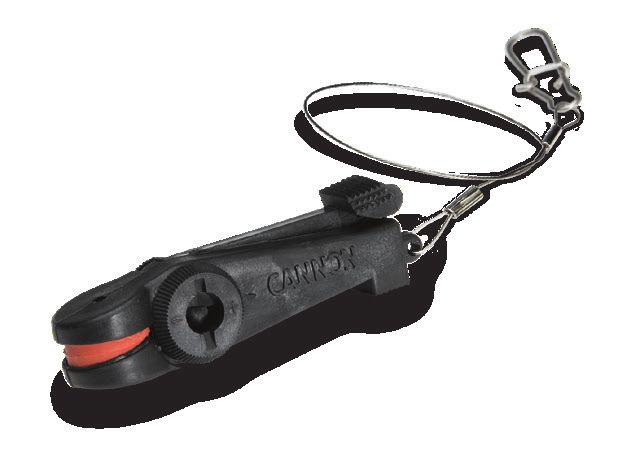
Installing the optimum

              MOUNTING CONSIDERATIONS

    Before mounting a Cannon downrigger, please give consideration
    to the following:
                                                                               Bow                                                    Stern
    1.   Clear mounting location - Choose a good location on your
         boat to mount your downrigger. Downriggers are mounted
         to the Gunwale of the boat. Make sure the area under the
         mounting location is clear to drill holes and install nuts and
         washers. Make sure that the mounting location is free from
                                                                                                                                    Gunwale
         cables or wiring and other critical boat structures. The                                                                 (Top Edge)
         movable parts of the downrigger, such as the telescopic
         boom should be positioned so that the weight is far enough
         beyond the edge of the boat so that it and the downrigger                                           Typical Mounting Location
         will not encounter any obstructions during operation. In
         some cases, the profile of the Gunwale is raised which may
         prevent the downrigger from sitting all the way against the face of the Gunwale. It may be necessary to shim or cut away around
         these areas to securely complete the installation. Mounting accessories are recommended to accommodate difference in
         mounting locations and mounting situations.

    2.   Operation of the downrigger - Consider the operation of the downrigger at the selected mounting location. A downrigger should be
         mounted in a location where it is easy to observe your fishing rod and react quickly to operate the downrigger once there is a fish
         on the line. There should be enough space to use the downrigger comfortably and with proper ergonomics. It should be easy to
         reach while still maintaining control of the boat and to retrieve gear. The location of the telescopic boom, weight and rod holder
         when fully installed should not encounter obstructions. The power cables should reach their intended power source from the
         mounting location. When installing multiple downriggers, consider the spacing between downriggers units. Mount the downrigger
         in a location where it is easy to route transducer cables and other downrigger accessory cables and wiring, either to a power
         source or sonar unit. Make sure that the mounting location does not create a tripping hazard for power cables or accessories
         used during operation.

    3.   Mounting accessories - Consider the use of a mounting                      NOTICE: When using the telescopic boom, we strongly
         accessory when installing your downrigger. Consider the                    recommend the use of a deck plate on all boats to provide
         location and angle of the rod placement when the downrigger                adequate stability for the downrigger.
         is fully installed on the mounting surface. A deck plate is
         recommended to provide adequate support and to maximize the capability of the product. Cannon offers a complete line of
         mounting accessories that allow you to optimize your installation to fit the way you fish. Before making any permanent changes to
         your boat, consider what accessories might be used in your application. To see the complete line of mounting accessories review
         the variety of accessories explained in this document or visit cannondownriggers.com.

6                                                                                © 2021   |   Johnson Outdoors Marine Electronics, Inc.   |   cannondownriggers.com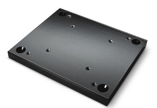
Installing the optimum
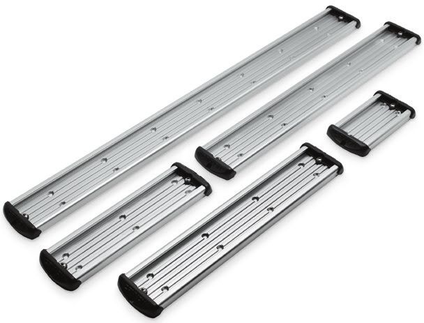
Side/Rail
Mount
Deck Plate
Gimbal
Mount
SIDE/RAIL MOUNTS DECK PLATES GIMBAL MOUNTS
Can be mounted to a welded Cannon deck plates prevent Designed to fit medium-sized
T-section. Side/Rail Mounts deflection and add stability flush mounted rod holders
(Item No. 2250940) can also be to decks. Recommended for built into the gunwale of larger
used at the two rail section butt attaching the downrigger fishing boats and cruisers.
joint. In both installations it is for initial installation or for Only sturdy, high quality rod
recommended to use a non-slip mounting accessories. They are holders should be used for this
material, such as rubber or a necessary to add extra strength temporary mounting system.
thin wood sheet, between to the base material of the Gimbal mounts are available
metal surfaces. boat. Options include Deck in 9” or 12” post lengths with
Plate (Item No. 2200693) . Standard (Item No. 2250927 and
2250928) and Stainless Steel
options (Item No. 1903005
and 1903006).
TOOLS AND RESOURCES REQUIRED
• 9/32” Drill Bit • Wire Cutters • Masking tape
• Pencil, Marker or similar Marking Tool • Pliers • Anti-seize
• Drill • #3 Phillips Screw Driver • A second person to help with
• 7/16” Box End Wrench • Needle Nose Pliers the installation
© 2021 | Johnson Outdoors Marine Electronics, Inc. | cannondownriggers.com 7
Installing the Base

             INSTALL ATION

    INSTALLING THE BASE
     1         Item(s) needed:

                                            #A x 1                          #C x 1                               #B x 1

               a.   Review the mounting considerations at the
                                                                                                     Downrigger
                    beginning of the installation and select a mounting         1a                    Assembly
                    location. Make sure the downrigger is not
                    connected to a power source.

                         WARNING                                                                   Power Cable

         Make sure the downrigger is not connected to a power source.

              b.    Take the Mounting Base (Assembly #C) and
                    attach it to the Downrigger Assembly (Assembly
                    #A). The Mounting Base is keyed with the bottom
                    of the Downrigger Assembly. The Soft Grip Knob
                    on the Mounting Base screws into a metal plate on
                    the bottom of the Downrigger Assembly. Secure the
                                                                                1b
                    Mounting Base to the Downrigger Assembly so that
                    the Soft Grip Knob is in the correct position.
                                                                                 Downrigger
              c.    In the final Installation, the Mounting Base is               Assembly
                    installed on the Swivel Base (Assembly #B). If                                   Metal
                                                                                                     Plate                                               Power
                    desired, hold the Downrigger Assembly (Assembly                                                                                      Cable
                    #A) with the Swivel Base at the selected mounting
                    location to check fit and function. Use a second                                                                    Downrigger           Soft
                                                                                 1b                                                      Assembly            Grip
                    person to help with the installation and test to make                                                                                    Knob
                    sure that the downrigger will operate as desired.

              d.    Determine if a mounting accessory, such as a
                    recommended deck plate is needed. Refer to
                    the installation instructions included with any                                                         Metal
                                                                                                                            Plate                  Mounting Base
                    mounting accessory and then complete the
                    downrigger installation.
                                                                                                                                       Downrigger
                                                                                 1c                                                     Assembly
            NOTICE: This downrigger weighs approximately
                                                                                                                                        Mounting Base
            19 lbs. We recommend having a second person help
            with the installation.
                                                                                                                                           Swivel Base

            NOTICE: The Release Knob on the Swivel Base can                                               Release Knob
            face any direction for your final installation.                                                                                            Mounting
                                                                                                                                                       Location

8                                                                                     © 2021   |   Johnson Outdoors Marine Electronics, Inc.   |   cannondownriggers.com
Installing the Base

    2              e.    Once satisfied with the selected location, begin by
                         using the Swivel Base as a mounting template.                2e                                  2f
                                                                                               Mounting Holes
                                                                                                                                   Swivel Base
                   f.    Take the Swivel Base and place it at the desired            Release                            Mounting              Mounting
                                                                                      Knob                               Hole                  Holes
                         location. Make sure that the Release Knob
                         is orientated in the desired direction and the
                         mounting location is clear to drill holes and can
                         accommodate mounting hardware.

                   g.    With the Swivel Base in place, use a pencil,                                                   Release
                         marker, or similar marking tool to mark the                                                     Knob Mounting Hole
                                                                                      Swivel                                              Mounting
                         location of the 4 mounting holes on the                                                                          Location
                                                                                       Base    Mounting Holes
                         mounting location.

                 NOTICE: When drilling holes, it is helpful to first cover                                                     Mounting Hole
                                                                                      2g    Mounting
                 the surface with masking tape. This will help keep the                      Hole
                 boat surface unmarked and help with cleanup. Cover
                                                                                     Swivel Base
                 the surface and then mark the location to drill. Once                Release Knob
                 the pilot holes are drilled remove the masking tape                         Marked                                         Marked
                 before continuing installation.                                            Location                                       Location

                                                                                                                                               Mounting
                                                                                                            Marked Location                    Location

    3              h.    With the location marked, set the Swivel Base
                         aside and drill holes, one in each of the four               3h
                                                                                                         Holes in Marked Location

                         marked locations using a Drill with a 9/32"
                         Drill Bit.

                   i.    Return the Swivel Base to the mounting location                    Marked                                          Marked
                                                                                           Location                                        Location
                         and align it with the four drilled holes. Orientate
                         it back in the desired direction so the mounting
                         holes in the Swivel Base align with the drilled
                         holes in the mounting location and the Release                                                                         Mounting
                                                                                                            Marked Location                     Location
                         Knob in the desired direction.

                 NOTICE: Mounting the Swivel Base is optional. If it                                                           Mounting Hole
                                                                                      3i   Mounting
                 is preferred to use the Mounting Base only, use the                        Hole
                 mounting base as a template for drilling holes. To                  Swivel Base
                 secure the Mounting Base to the deck use four 1/4-20                 Release Knob
                 X 2" Phillips Truss Head Machine Screws (Item # 2)                            Holes                                      Holes
                 four Flat Washers (Item #4) and four 1/4-20 Nylock
                 Nuts (Item # 6).

                                                                                                                                                Mounting
                                                                                                                Holes                           Location

© 2021   |   Johnson Outdoors Marine Electronics, Inc.   |   cannondownriggers.com                                                                         9
Installing the Base

     4     Item(s) needed:

                #2 x 4            #4 x 4               #6 x 4

           j.   Take four of the 1/4-20 X 2" Phillips Truss Head
                Machine Screws (Item # 2) and apply anti-seize.        4j
                                                                             Phillips
                Then place one in each of the Mounting Holes. The            Screws                                                         Phillips
                                                                                                                                            Screws
                Truss Screws should pass through the Swivel Base
                and the drilled holes in the mounting location.
           k.   Secure the Truss Screws in place with four Flat              Swivel
                Washers (Item #4) and four 1/4-20 Nylock Nuts                 Base
                (Item # 6). Take one Flat Washer and place it on
                the end of each Truss Screw. Secure each Truss
                Screw and Flat Washer with Nylock Nuts using a
                                                                                                 Flat              Flat                        Mounting
                #3 Phillips Screwdriver. Hand tighten, or tighten to                            Washer                                         Location
                                                                               Flat                               Washer
                45 ft-lbs. To prevent seizing of the stainless steel          Washer                                                      Flat
                hardware, do not use high speed installation tools.                                                                      Washer
                                                                                               Nylock Nuts              Nylock Nuts
         NOTICE: To prevent seizing of the stainless steel
         hardware, do not use high speed installation tools.                                            Swivel Base
         Wetting the screws or applying an anti-seize may help         4j
                                                                             Phillips                                                    Phillips
         prevent seizing.                                                    Screws                                                      Screws

         NOTICE: Consider installing an optional Cannon Lock on
         the Mounting Base for added security. (Item No. 1903020)                                                                Mounting Location

     5     Item(s) needed:

                #8 x 4

           l.   The Mounting Base will be installed to the Swivel                                                           Truss Head Screws
                Base. At the beginning of the installation, the        5l                                            5m
                Mounting Base was attached to the Downrigger
                Assembly. Recall the orientation of the Soft
                Grip Knob and the orientation of the Downrigger
                                                                       Swivel
                Assembly in its intended installation position.         Base
           m. Remove the Mounting Base from the Downrigger
                                                                                     Mounting Holes
              Assembly and place it back on the Swivel Base
              in the same orientation. The mounting holes in                                                      Mounting
                                                                                                                   Base
              the corners of both the Swivel Base and Mounting
              Base should align. Take four of the 1/4-20 X 1 1/2"
              Truss Head Screws (Item # 8) and use them to
              secure the Mounting Base to the Swivel Base using
              a Phillips screwdriver.
                                                                                                Mounting             Mounting
                                                                         Mounting Holes          Base                Location               Swivel Base

10                                                                          © 2021   |   Johnson Outdoors Marine Electronics, Inc.   |   cannondownriggers.com
Installing the Clutch Knob
6 n. Once the bases are secured together, replace the
Downrigger Assembly on the Mounting Base and 6n Downrigger Assembly
secure it with the Soft Grip Knob. Hand tighten.
Spool
Soft
Grip
Knob
Mounting Base
Mounting Location
Swivel Base
INSTALLING THE CLUTCH KNOB
1 Item(s) needed:
#10 x 1
a. Take the Clutch Knob (Item #10) and install it into
Downrigger
the side of the Downrigger Assembly. The Clutch 1a Assembly
Knob is installed on the side of the downrigger
where the Spool is located. When installing the Spool
Clutch Knob, insert it into the center of the
downrigger spool and turn it counterclockwise
to tighten.
Clutch
Knob
© 2021 | Johnson Outdoors Marine Electronics, Inc. | cannondownriggers.com 11Installing the Telescopic Boom
INSTALLING THE TELESCOPIC BOOM
1 Item(s) needed:
#D x 1 or #E x 1
a. Take the Telescopic Boom (Assembly #D or
Boom Clamps
Assembly #E) and cut the Cable Tie holding the 1a Telescopic Boom
three tubes of the boom together with a wire
cutter or cutting tool. Remove the cut Cable Cable
Tie and loosen the Boom Clamps by turning Tie
them counterclockwise at the narrow end of the
Telescopic Boom.
Narrow End Wide End
b. The Outer Tube that makes up the wider end of the
Telescopic Boom has 3 holes used for mounting Telescopic Boom Mounting Hole Not a through
1b Mounting Hole
it to the Downrigger Assembly. The tubes in the
Telescopic Boom need to be extended so that the
holes used to mount the boom to the downrigger are
unobstructed and are free to pass a bolt through.
Mounting Hole
c. With the Clamps on the Telescopic Boom loosened,
Narrow End Wide End
the tubes of the boom can slide apart. Slide the
Center Tube about 2 inches out from the original
Boom Clamp Boom Clamp
position and then re-tighten the Boom Clamp 1c
towards the narrower end of the boom turning Middle Outer
Center Tube Tube Tube
clockwise. Slide the Middle Tube about 2 inches
out from its original position and tighten the second
clamp. Check the opposite end of the boom to see
if all three holes on the Outer Tube are clear to
pass mounting hardware. If not, re-adjust the Boom
Telescopic Boom
Clamps and tubes to expose the mounting holes. Narrow End Wide End
Secure the clamps by turning them clockwise so
that the tubes do not slide, then set aside.
2 Item(s) needed:
#12 x 1 #14 x 1
d. Take the Ball Hook (Item #14) and place the
Stainless Steel Hex Nut (Item #12) on it. Turn the 2d 2d Stainless
Steel Hex Nut
Hex Nut far onto the Ball Hook, nearly to the end
of the threads. Set the Ball Hook Assembly aside.
Stainless
Steel Hex Nut
Ball Ball Hook
Hook
12 © 2021 | Johnson Outdoors Marine Electronics, Inc. | cannondownriggers.comInstalling the Telescopic Boom
3 Item(s) needed:
#18 x 1
e. Take the Ball Hook Extrusion (Item #18) and
Ball Hook
place it over the wider end of the Telescopic 3e Extrusion
Boom, opposite the Clamps. At this point on the
Telescopic
installation, the Ball Hook Extrusion will slide Boom
freely on the Telescopic Boom.
Wide End Narrow End
f. Take the Telescopic Boom with the Ball Hook
Extrusion and note the location of the three holes
on the wide end of the boom. The two holes across 3e
from each other will be used to secure it to the Ball Hook
Downrigger Assembly. The two holes are aligned so Extrusion
that hardware can pass straight through to secure Telescopic
it to the Downrigger Assembly. Place it into the end Boom Wide End Narrow End
of the Downrigger Assembly and rotate the holes
so that the mounting holes in the Boom Assembly
3f Ball Hook
are aligned with the mounting holes in the
Extrusion
Downrigger Assembly.
Downrigger Assembly
NOTICE: If preferred, rotate the Boom Assembly so Telescopic
that the plastic protrusion toward the Narrow End of the Boom
boom, next to the Boom Clamp, is rotated downward. Mounting Holes
This is a cosmetic preference and will not affect the
operation of the Boom. Mounting Hole
4 Item(s) needed:
#6 x 1
g. The Boom Assembly will be held in place with
Downrigger Assembly Downrigger Assembly
a Screw and Hex Nut. On the back side of the 4g 4g
Downrigger Assembly, on the Motor Side, is a Telescopic Telescopic
Boom Boom
keyed impression for the Nylock Nut. Take the
Nylock Nut (Item #6) and press it into the Motor
Side of the downrigger, opposite of the Spool Side.
The Nylock Nut should be pressed in with the
Curved Edge of the Nylock Nut facing outward. Curved
Edge
Nylock
Nut
Nylock Nut
Motor Side Motor Side
© 2021 | Johnson Outdoors Marine Electronics, Inc. | cannondownriggers.com 13Installing the Telescopic Boom
5 Item(s) needed:
#16 x 1
h. The 1/4-20 X 2" Phillips Pan Head Screw (Item
#16) will be used to secure the Telescopic Boom 5h
Ball Hook
to the Downrigger Assembly. The Phillips Pan Spool Extrusion
Head Screw will pass from the spool side of the Telescopic
downrigger to the opposite side of the Downrigger Boom
Assembly and through the Boom Assembly. On
the Motor Side of the Downrigger Assembly the
Phillips Pan Head Screw will be secured into the
Hex Nut installed above. Tighten the Phillips Pan
Head Screw with a Phillips screwdriver until the Phillips Pan
Downrigger Head Screw
end of the bolt is flush with the top of the Nylock Assembly
Nut on the reverse side of the downrigger.
6 i. With the Telescopic Boom secured to the
Downrigger Assembly, slide the Ball Hook 6i Ball Hook
Extrusion down on the boom until it is seated Extrusion
against the Downrigger Assembly. Rotate the Telescopic
Downrigger Assembly
Ball Hook Extrusion so that the Screw Hole is Boom
facing downward. Screw Hole
j. Attach the Ball Hook Assembly into the Ball
Hook Extrusion and hand tighten it until the Ball
Hook Assembly has tightly secured the Ball Hook
Extrusion in place on the Telescopic Boom. Turn
the Ball Hook until the hook is in the desired
orientation, turning clockwise. Ball Hook
6j Extrusion
Telescopic
NOTICE: Do not over-tighten the Ball Hook Assembly Boom
or denting of the Telescopic Boom is possible. Screw Hole
Ball Hook
Assembly
Downrigger Assembly
14 © 2021 | Johnson Outdoors Marine Electronics, Inc. | cannondownriggers.comInstalling the SWIVEL HEAD/BOOM END
7 k. Secure the orientation of the Ball Hook by turning
the Hex Nut on the Ball Hook Assembly until it is 7k
Ball Hook Extrusion
7k
Ball Hook Extrusion
seated tightly against the Ball Hook Extrusion with
a 7/16" wrench. Hand tighten until secure.
Telescopic Telescopic
Boom Boom
Hex Hex
Downrigger Nut Nut
Downrigger
Assembly Assembly
Ball Hook Ball Hook
INSTALLING THE SWIVEL HEAD/BOOM END
1 Item(s) needed:
#28 x 1 #K x 1
a. Next install the Boom End (Assembly #K) on the end Boom End
of the Telescopic Boom. Take the Boom End and find 1a
the mounting hole along the shaft. The mounting
Shaft
hole in the Shaft of the Boom End should be aligned
with the mounting hole in the Center Tube at the
narrow end of the Telescopic Boom. Center Tube
Mounting
b. Once aligned, take the #8-18 X 5/8" Screw (Item Holes
#28) and insert it into the end of the Boom
Assembly. Secure the screw with a Phillips Head
screwdriver by turning clockwise.
Telescopic Boom Wide End Narrow End
1b Boom
End
Center Tube
Telescopic
Boom
© 2021 | Johnson Outdoors Marine Electronics, Inc. | cannondownriggers.com 15Terminating the Downrigger Line
TERMINATING THE DOWNRIGGER LINE
With the body of the Cannon downrigger installed, the Line on the
Spool can be terminated. The downrigger comes standard with To watch a video of Terminating the
stainless steel Line held in place on the Spool with a Rubber Band. Cannon Downrigger, follow the link
During the termination, it is very important to keep tension on the on-line at https: //www.youtube.com /
Line to keep it wound tightly around the Spool. To keep tension watch?v = sQKp73j3aaw
on the Spool, the Clutch Knob is first installed and then the Line
is routed and terminated. Check to determine that the Clutch
NOTICE: It may be necessary to have a second person
Knob was installed by referring to the "Installing the Clutch Knob"
help with terminating the Line.
section of these instructions. If installed, complete the terminating
procedure by following these steps:
1 a. Locate the Rubber Band on the Line. The Rubber
Band is securing both the end of the Line tight 1a
Spool
and holding the Line around the Spool. Keep the
Rubber Band secured to the end of the Line, but
loosen it from the Spool so that tension can be
kept on the Line end by pulling on the Rubber
Band. Once it is loose from the Spool, keep
tension on the end of the Line by holding the
Rubber Band tight.
Line
b. The Line is wound around the Spool in a Routing
counterclockwise direction. Work with the end of
the Line the Rubber Band is attached to, so that Spool
the end of the Line comes out of the downrigger 1b
on the bottom side of the Spool below the Telescopic
Telescopic Boom. Boom
NOTICE: While terminating the Line, it is very Bolt Hook
important to keep tension on the Line to keep it wound Line Assembly
Routing
tightly around the Spool.
Line
c. Pull the Line tight by keeping it secure with Exit
the Rubber Band. Slide it through the Bolt
Hook Assembly. Line
Telescopic
1c Boom
Rubber
Band
Bolt Hook
Assembly
Line
16 © 2021 | Johnson Outdoors Marine Electronics, Inc. | cannondownriggers.comTerminating the Downrigger Line
2 d. The Clutch Knob holds tension on the Spool.
Loosen the Clutch Knob on the side of the 2d Spool
downrigger by turning it clockwise while
keeping tension on the Line. Pull the Line
so that there is enough slack to feed the Line
Clutch
through the Pulley. Knob
e. Feed the Line through the Pulley on the
Boom End so that it exits the Pulley on the far
end of the Pulley away from the base of the Boom End
downrigger. Once it passes through the 2e 2f
Pulley, pull approximately 2 feet of Line through
the Pulley.
Pulley
f. Re-tighten the Clutch Knob by turning it
counterclockwise and keep tension on the Line.
Clutch
Knob
Line Rubber
Band
3 Item(s) needed:
#30 X 1
g. Have a second person hold the Line just past the
downrigger Boom End to keep tension on the 3g Boom End
Line. Remove the Rubber Band from the end of
the Line. Pulley
h. Take a wire cutter and remove any worn or
kinked Line. Telescopic
Boom
Line
NOTICE: When routing Line through the Terminator,
use only straight Line. Worn or kinked Line can be
stressed and may break prematurely when retrieving
trolling weights.
3i
i. Take the Cushion Sleeve Terminator (Item #30) Cushion Sleeve
Terminator
and feed the Line so that the narrower end of the
sleeve is threaded first. Thread about a foot of Line
through the Cushion Sleeve Terminator. Line
© 2021 | Johnson Outdoors Marine Electronics, Inc. | cannondownriggers.com 17Terminating the Downrigger Line
4 Item(s) needed:
#32 X 1 #36 X 1
j. Take the Snap Swivel (Item #36) and attach it to
Cannon
the hook at the bottom of the Cannon Terminator 4j Terminator
(Item #32). The Snap Swivel can be attached
by inserting the end with the smaller metal loop
onto the open end of the Bottom Hook on the Snap Swivel
Bottom
Terminator. It may be helpful to use a pliers to link Hook
the pieces together.
4j Snap Swivel
Cannon Terminator
5 k. With the Snap Swivel attached to the Cannon
Terminator, identify the front and back of the 5k Back Front
Terminator. Also look at the holes along the Top
Holes
Fold and Bottom Hook of the Terminator. There
Top Fold
are three holes along the Bottom Hook of the
Cannon
Terminator, one on each side of the hook and one Terminator Top Fold
in the middle. There are also 3 holes along the Top Holes
Fold all in close proximity to each other. The Line Holes
Bottom Hole
from the downrigger will be routed through the Hook
Snap Bottom Hook
holes to terminate it.
Swivel
5k
Top Fold
Cannon
Terminator
Back
5k
Cannon
Terminator
Snap Swivel
Bottom Hook Front
18 © 2021 | Johnson Outdoors Marine Electronics, Inc. | cannondownriggers.comTerminating the Downrigger Line
6 l. Turn the Terminator so that back side is facing
toward you. The opening to the Bottom Hook Cannon
6l Terminator 6m
should be on the left. With the Terminator in
this orientation, place the freshly trimmed Line
into the hole furthest to the right along the top
hole so that the Line passes from the back of the
Terminator through the hole to the front of Line
the Terminator.
Cannon
m. When the Cannon Terminator is turned over facing Terminator
forward, the Line should follow the Track along the
Track
left side of the Terminator to the Bottom Hook. The
Line should then be pulled to exit out the bottom Line
along the closed side of the Bottom Hook. Pull
about 6 inches of Line from the bottom of
the Terminator.
n. With the Line exiting the bottom of the Bottom Hook
Terminator, slide the Line along the Bottom Hook Opening
so that is passes through the loop of the Snap Bottom
Swivel linked on the Bottom Hook. Hook
Opening Back Front
o. With the Line through the loop on the Snap Swivel,
pass it along the Bottom Hook of the Terminator
6n
and insert it into the hole in the space at the far
end of the Terminator where the Bottom Hook is
detached from its base. Pull about 6 inches of the Cannon
Terminator
Line through the hole.
Bottom Hook
NOTICE: When routing the Line through the Snap Swivel
Terminator, there may be areas where there is slack in
Line
the Line. While routing the Line, it is okay for slack to
be present. At the end of the termination process, the
slack will be pulled tight. Be sure that the slack in the Front
Line does not get kinked, to keep the Line easy to feed
through the Terminator.
6o Bottom
Hook
Line Opening
Cannon
Terminator
Snap Swivel Line
Bottom Hook Front
© 2021 | Johnson Outdoors Marine Electronics, Inc. | cannondownriggers.com 19Terminating the Downrigger Line
7 p. With the front of the Cannon Terminator still facing
toward you, take the Line and place it along the 7p
track along the right side of the Terminator and
Cannon
insert it so that it exits the hole at the far end of Terminator
the track. The Line will exit the hole towards the Line
back side of the Terminator.
q. Turn the Terminator over so the back side is facing
toward you. Pull about 6 inches of slack through
the Terminator.
r. Take the end of the Line and put it through the
hole on the back of the Terminator right next to Line
the hole that the Line was just fed out of. The hole
is in the middle of the Terminator and is directly Front
between the hole that the Line just exited and
the very first hole that the Line was fed through Line from
7r 7r
on the Terminator. Downrigger
Line
Line
Cannon
Terminator
Cannon
Terminator
Line
Back Back
8 s. Turn the Terminator over so that the front of it
is facing towards you. The end of the Line that 8s
was just inserted into the back of the Terminator Middle
should run along the track in the middle of the Cannon Track
Terminator
Terminator. Feed the Line all the way along this Line
Track so that it exits the hole in the middle of the Line
Terminator along the middle of the Bottom Hook
at the end of the Track. The Line should stick
out about 1/8 inch from the Terminator along the
Bottom Hook.
1/8 inch
Front
Bottom
Hook
20 © 2021 | Johnson Outdoors Marine Electronics, Inc. | cannondownriggers.comTerminating the Downrigger Line
9 t. With the End of the Line sticking out the final
hole by the Bottom Hook, hold the Terminator and 9t 9t
squeeze the Line in the middle track to hold it in
place. While keeping the end of the Line in place,
pull the Line wound through the Terminator in the Line from
opposite direction, so that the slack is pulled tight. Downrigger
Use a pliers if necessary to get the Line tight.
Cannon
Terminator
Cannon
Terminator
Line
Line
Line
Line
Bottom
Line Hook
End Line
Front End Back
10 u. With the Line tight, close the Cover of the
Terminator so that the Clip in the middle of the 10u Cover 10u
top cover captures the Line. Use a Pliers to close
the Terminator if necessary. With the Terminator
closed, Slide the Cushion Sleeve Terminator Clip
securely over the Terminator until it is seated
against it. Once fully seated, the downrigger is
successfully terminated. A Cannon Weight can Cannon
Terminator
then be attached directly to the Snap Swivel. Cushion Line
Sleeve
Terminator
CAUTION Cannon
Capture
Do not overload the downrigger. It is designed to retrieve a Line Terminator
maximum of 20 lb. weights only. Here
Line
Bottom Line
Line Hook
End End
Front Front
Snap Cushion Sleeve Terminator
10u Swivel
Cannon Terminator Line
© 2021 | Johnson Outdoors Marine Electronics, Inc. | cannondownriggers.com 21Installing the Rear Mount Rod Holder
INSTALLING THE REAR MOUNT ROD HOLDER
The Cannon Optimum downrigger comes with two Rear Mount Rod
Holders, while the Cannon Optimum TS comes with one. The Rod NOTICE: The Rod Holder assembly is not covered under
Holder(s) incorporate a two-piece locking tooth design. This allows warranty when used with tackle above 30 lbs. Equipment
independent adjustment of the Rod Holder along two axes, which placed in the Rod Holders and the loss thereof is the
can be easily adjusted every 15° of rotation. The symmetrical responsibility of the user and is in no way warranted by
design will allow mounting of the Rod Holder on either side of the Johnson Outdoors, Inc. Mounting must be in accordance
downrigger or two Rod Holders at the same time. The spring along with the instructions to comply with the product warranty.
the shaft of the Soft Grip Knob allows the knob to be loosened and
the Rod Holder to be indexed without fully disassembling it. To install, follow the steps below.
CAUTION
The Rod Holder is intended for use of up to 30lb test line only and is not recommended for use with any tackle IGFA (International
Game Fish Association) rated higher than 30lb. A safety strap (not included) is recommended for all applications.
1 Item(s) needed:
#20 X 1 or 2 #22 x 1 or 2 #26 x 1 or 2
a. Depending on the Downrigger, it will come with
either one or two Rod Holders. To secure the Rod 1a 1a
Holder(s) on the Downrigger Assembly, take one Soft Grip Knob Spring Release
or two Soft Grip Knobs (Item #20) and one or two
Spring Releases (Item #22). Place one spring on
the end of each Soft Grip Knob.
b. If the downrigger came with one Rod Holder,
determine which side of the downrigger to install Spring Release Soft Grip Knob
the Rod Holder on based on how your downrigger
is mounted and how it will be used. Once the
location of the Rod Holder is determined, take 1b Soft Grip Dual Axis
Knob Rod Holder
the Dual Axis Rod Holder Arm (Item #26) and Arm
turn it so that the short end of the elbow will be
placed against the Downrigger Assembly. The face
of the Dual Axis Rod Holder Arm that is installed
Motor Side Spool Side
on the downrigger contains keyed teeth which are
matched on the Dual Axis Rod Holder Arm. These
keyed teeth will help to hold the position of the 1b Dual Axis Rod
knob and help to hold it in place when the position Holder Arm
of the holder is changed during use. Secure the
Soft Grip
Dual Axis Rod Holder Arm with the Soft Grip Knob. Knob
NOTICE: The Tournament Series Optimum downrigger
comes with one Rod Holder, the standard Optimum
downrigger comes with two Rod Holders.
Motor Side Spool Side
22 © 2021 | Johnson Outdoors Marine Electronics, Inc. | cannondownriggers.comInstalling the Rear Mount Rod Holder
2 Item(s) needed:
#20 X 1 or 2 #22 x 1 or 2 #34 X 1
c. A Soft Grip Knob will be used to secure the Dual
Axis Rod Holder Tube to the Arm just installed. 2c 2c
Spring Release
Take one or two Soft Grip Knobs (Item #20) and Soft Grip Knob
one or two Spring Releases (Item #22). Place one
spring on the end of each Soft Grip Knob.
d. Take the Dual Axis Rod Holder Tube (Item #24)
and turn it so that the short end of the piece will Spring Release Soft Grip Knob
be placed against the Dual Axis Rod Holder Arm.
The face of the Dual Axis Rod Holder Arm that
contains keyed teeth which are matched on the 2d
Dual Axis Rod Holder Tube. These keyed teeth will
Soft Grip
help to hold the position of the knob and help to Knob
hold it in place when the position of the holder
is changed during use. Secure the Dual Axis Rod
Holder Tube with the Soft Grip Knob.
Short End
e. To adjust the direction of the Dual Axis Rod Holder Dual Axis
Arm or tube, loosen the Soft Grip Knob and rotate Rod Holder
Arm
in the desired direction. Then re-tighten the Soft
Grip Knob to secure in place.
NOTICE: The Soft Grip Knobs and Spring Releases will
2e Dual
be inside the Dual Axis Rod Holder Tube. Axis Rod
Holder
Tube
Soft
Grip
Knob
Soft Grip
Knob
Dual Axis Rod
Holder Arm
© 2021 | Johnson Outdoors Marine Electronics, Inc. | cannondownriggers.com 23WIRING THE DOWNRIGGER
RIGGING & INSTALLATION GUIDELINES
For safety and compliance reasons, we recommend that you follow American Boat and Yacht Council (ABYC) standards when rigging
your boat. Altering boat wiring should be completed by a qualified marine technician. The following specifications are for general
guidelines only:
CAUTION
These guidelines apply to general rigging to support your Cannon product. Powering multiple downriggers or additional electrical
devices from the same power circuit may impact the recommended conductor gauge and circuit breaker size. If you are using wire
longer than that provided with your unit, follow the conductor gauge and circuit breaker sizing table below. If your wire extension
length is more than 30 feet, we recommend that you contact a qualified marine technician.
CAUTION
Please read the following information before connecting your downrigger to a battery in order to avoid damaging your product and/
or voiding your warranty.
CONDUCTOR GAUGE AND CIRCUIT BREAKER SIZING TABLE
This conductor and circuit breaker sizing table is only valid for the following assumptions:
1. No more than 2 conductors are bundled together inside of a sheath or conduit outside of engine spaces.
2. Each conductor has 105° C temp rated insulation.
3. No more than 5% voltage drop allowed at full motor power based on published product power requirements.
Fuse/Breaker Specifications Wire Specifications
10 Gauge 8 Gauge 6 Gauge
30 Amp, 32 Volt, Waterproof, Fast Blow 0-10 feet 11-15 feet 16-20 feet
0-3 meters 3-4.5 meters 4.5-6 meters
CAUTION
An over-current protection device (circuit breaker or fuse) must be used. Coast Guard requirements dictate that each ungrounded
current-carrying conductor must be protected by a manually reset, trip-free circuit breaker or fuse. The type (voltage and current
rating) of the fuse or circuit breaker must be sized accordingly to the Cannon downrigger used.
Reference - United States Code of Federal Regulations: 33 CFR 183 – Boats and Associated Equipment ABYC E-11: AC and DC Electrical Systems on Boats
24 © 2021 | Johnson Outdoors Marine Electronics, Inc. | cannondownriggers.comWIRING THE DOWNRIGGER
RECOMMENDATIONS FOR MAINTAINING BOAT’S ELECTRICAL CONDITION
Whenever a boat is in water, various submerged parts interact to
create weak electrical currents. These weak electrical currents NOTICE: To ensure proper operation of your downrigger,
should be controlled to extend the life of the boat’s metal parts ground the downrigger battery to your boat’s electrical
and ensure a good fish catching environment. In order for the system’s ground. Always check to see if your boat is
Positive Ion Control and Short Stop (PIC) on your downrigger to properly grounded first. Malfunctions with the Positive
work correctly, it is important to make sure your boat is properly Ion Control, communication between units, or loss of
set up before installing your downrigger. For full details on how the operation result from faulty grounding.
Positive Ion Control system works, see the “Positive Ion Control”
section of the Owner's Manual.
• If the zinc sacrificial anodes on your boat and on the outboard/outdrive are more than half dissolved, it is recommended that they
be replaced. Clean anodes on a regular basis with a non-corrosive brush.
• Any coating of slime or growth on the boat should be cleaned off.
• All metal parts including the hull (if metal) should be interconnected by a grounding wire. This includes motor shafts, outdrives,
and through hull fittings. This will ensure that the boat is properly grounded to the water and allow Positive Ion Control and Short
Stop to work correctly.
• The line on your downrigger should be replaced every 2 years. Etching of the line can weaken it physically and electrically.
• The use of Cannon coated weights and the snap assembly with the insulator will help insulate the weight from the positively
charged line.
ELECTRICAL SPECIFICATIONS & WIRING INSTRUCTIONS
The downrigger is rated at 30 amps (full load), 12 volts DC and
is protected by a 25 amp manual reset circuit breaker (located
under motor housing). Be sure to measure the battery voltage
of your boat.
WARNING
Do not run this downrigger on a 24 volt or higher battery 25 amp
manual
system. This will damage the unit and void your warranty. reset circuit
Only connect your downrigger to a 12 volt battery system. breaker
WARNING
It is strongly recommended to power your downrigger with a battery capable of providing high currents for an extended period of
time. Only run a downrigger from a Starter battery if it is recharged by an alternator while the downrigger is running.
WARNING
Never connect the (+) and the (–) terminals of the same battery together. Take care that no metal object can fall onto the battery
and short the terminals. This would immediately lead to a short and extreme fire danger.
© 2021 | Johnson Outdoors Marine Electronics, Inc. | cannondownriggers.com 25WIRING THE DOWNRIGGER
CONNECTING TO THE BATTERY
It is strongly recommended that a fuse or manual reset circuit breaker be installed within 7 inches from the battery on the positive lead
of the power cable. In addition, you may also connect the downrigger to a battery selector switch. It is strongly recommended to power
your downrigger with a Deep-Cycle marine battery. Only run a downrigger from a Starter battery if it is recharged by an alternator while
the downrigger is running.
1. Make sure that the downrigger is powered "off" or the Quick
Power Cable
Connect Plug on the downrigger Power Cable is disconnected. from Downrigger
2. Connect positive ( + ) red lead to positive ( + )
battery terminal.
3. Connect negative ( – ) black lead to negative ( – ) Fuse
Positive (+)
battery terminal. red Lead
4. Reconnect the Quick Connect Plug when ready to use
the downrigger. Negative (-)
black Lead Quick
Connect
NOTICE: Control degradation of the power cables Plug
Pos + Neg -
and limit corrosion by using anti-oxidant gel on all
connections. Do not use wing nuts. 12 Volt Battery
CAUTION
Refer to “Conductor Gauge and Circuit Breaker Sizing Table” in the previous section to find the appropriate circuit breaker or fuse
for your downrigger.
WARNING
For safety reasons, disconnect the downrigger from the battery when the downrigger is not in use or while the battery/batteries
are being charged. If installing a leadwire plug, observe proper polarity and follow instructions in your boat owner’s manual. Keep
leadwire connections tight and solid to battery terminals. Locate battery in a ventilated compartment.
POWERING MULTIPLE Quick Connect Plug
DOWNRIGGERS
When operating multiple downriggers, run a maximum of 2 Cannon #1
downriggers per dedicated 12 volt battery. Follow the instructions
from the "Connecting to the Battery" section of these Installation Power Cable
Instructions. Repeat the directions for each downrigger. from Downrigger
Fuse
Positive (+)
NOTICE: Use the Quick Connect Plug to remove red Lead Cannon #2
power from the downrigger without touching
Negative (-)
the battery. black Lead Quick
Connect
Plug
Pos + Neg -
12 Volt Battery
26 © 2021 | Johnson Outdoors Marine Electronics, Inc. | cannondownriggers.comWIRING THE DOWNRIGGER ADDITIONAL CONSIDERATIONS ADDITIONAL ACCESSORIES CONNECTED TO DOWNRIGGER BATTERIES Significant damage to your Cannon downrigger, your boat electronics, and your boat can occur if incorrect connections are made between your downrigger batteries and other battery systems. It is recommended to use an exclusive battery system for your downrigger. Where possible, accessories should be connected to a separate battery system. Radios and sonar units should not be connected to any downrigger battery systems as interference from the downrigger is unavoidable. If connecting any additional accessories to any downrigger battery system, or making connections between the downrigger batteries and other battery systems on the boat, be sure to carefully observe the information below. The negative (-) connection of an accessory device must be connected to the negative terminal of the same battery that the downrigger negative lead connects to. Connecting to any other downrigger battery will input positive voltage into the “ground” of that accessory, which can cause excess corrosion. Any damage caused by incorrect connections between battery systems will not be covered under warranty. AUTOMATIC JUMP START SYSTEMS AND SELECTOR SWITCHES Automatic jump start systems and selector switches tie the negatives of the connected batteries together. Please see a qualified marine technician if installing your Cannon downrigger with one of these systems or a selector switch. SELECTING THE CORRECT BATTERIES The downrigger will operate with any lead acid deep cycle marine or Lithium 12 volt battery/batteries. For best results, use a deep cycle marine battery. Maintain battery at full charge. Proper care will ensure having battery power when you need it, and will significantly improve the battery life. Failure to recharge lead-acid batteries (within 12-24 hours) is the leading cause of premature battery failure. Use a multi-stage charger to avoid overcharging. We offer a wide selection of chargers to fit your charging needs. If you are using a crank battery to start a gasoline outboard, we recommend that you use a separate deep cycle marine battery/batteries for your Cannon downrigger. © 2021 | Johnson Outdoors Marine Electronics, Inc. | cannondownriggers.com 27
SETUP GUIDE
     SETTING UP THE OPTIMUM TM
     When powering the downrigger "on" for the first time, the Color LCD will bring up a Setup Guide. In order to follow through the Setup
     Guide, first become familiar with the downrigger keypad. When comfortable with the keypad, follow through the Setup Guide to customize
     downrigger settings before beginning to use the downrigger for fishing. The Setup Guide will also appear the first time that the downrigger
     is powered "on" after the defaults have been restored.

               DOWNRIGGER KEYPAD

                                                   Preset
                                                   Depths                                       Exit

                                                     Up
                                                                                               Auto
                                                                                                Up
                                                    Left                                       Right

                                                   Down                                         Power

                                                   Menu

            POWER - When the downrigger is "off", press to turn the downrigger "on". When the downrigger is "on", a quick press will open
            the Power Menu or pressing and holding for 3 seconds will power the downrigger "off".
            UP - When all menus are closed, press to control the Spool to bring the weight up and the line in. The weight will continue to come
            up until the button is released or the line counter reaches "0". If the downrigger is currently moving the line when pressed, it will
            cancel the action. When any menu is open, pressing it will cycle up through the menu options. If the menu reaches the top of the
            list it will move to the bottom and continue to move up the options.
            AUTO UP - Single press to automatically bring the weight up and the line in at speed 5. The weight will continue to come up until
            the line counter reaches 0 or Short Stop is engaged even when the button in released. Single press and hold to bring the weight up
            for all downriggers in the Network. Use the Right   button to confirm the Auto Up All selection. The weights for all downriggers
            will continue to come up following the same controls for a single downrigger.
            DOWN - When all menus are closed, press to control the Spool to send the weight down and the line out. The weight will
            continue to go down until the button is released or the line is completely let out. If the downrigger is currently moving the line
            when pressed, it will cancel the action. When any menu is open, pressing will cycle down through the menu options. If the
            menu reaches the bottom of the list it will move to the top and continue to move down the options.
            LEFT - Press to make selections, adjustments to menus or change Views.
            RIGHT - Press to make selections, adjustments to menus or change Views. When menu selections are finalized, press to close
            the menu.
            MENU - When the Color LCD has any one of the Views open on the screen, a single press will open the Quick Menu for the View
            displayed. Double press from any View to open the Settings Menu. If the Settings Menu is open, pressing again will close the
            menu. If a Quick Menu is open, a single press will open the Settings Menu.
            PRESET DEPTHS - Press to open the Preset Depths Menu and to access Last Depth Recall.
            EXIT - Press to exit or close menus. Returns Color LCD to the last screen or View.

28                                                                                © 2021   |   Johnson Outdoors Marine Electronics, Inc.   |   cannondownriggers.com
SETUP GUIDE
SETUP GUIDE
The Setup Guide is a set of menus that help the user select settings to help with
downrigger operation. All of the options in the Setup Guide can be accessed in menus
within the downrigger if preferences change after initial setup. The Setup Guide will first
bring up a menu that gives the user the option to select Language, Battery Alarm,
Temperature, Depth/Distance and Speed. Use the Up button and the Down button to
scroll to the options in the list and use the Right button and the Left button to change
the setting for each one. Once the options in the first menu are selected, scroll to the
Continue option and use the Right button to select it. This brings up a second menu in
the Setup Guide. The second menu allows the user to select the amount of Line on Spool,
Line Type and Line Weight. The second menu is navigated in the same way as the first.
Once happy with the selections, scroll to the Complete Setup option and use the Right
button to select it. After the second menu is complete, the downrigger will bring up
information on the Cannon Transducer. Read the information on the Color LCD and then
use the Right button to Select next. This is followed by a message about the Fish Hawk
and Humminbird® fish finder. Read the messages and then use the Right button to select
Next. Selecting next on the Humminbird screen completes the Setup Guide.
LANGUAGE - Choose between 1 of 22 languages. The default language is English. Use
the Right button to confirm the language and make sure that the radio button to
the right of the desired language is selected.
BATTERY ALARM - Shows an alarm when the battery drops below a certain voltage.
The default is set to "off", but can be adjusted between 9.0V and 13.5V. Use the Right
button or the Left button to edit the sliding scale.
TEMPERATURE - Sets the temperature readings to Fahrenheit or Celsius. Use the Right
button or the Left button to scroll between the options. The default is set to Fahrenheit.
DEPTH/DISTANCE - Sets the Distance and Depth reading measurements in units of Feet
or Meters. Use the Right button or the Left button to scroll between the options.
The default is set to Feet.
SPEED - Sets the Speed measurements in units of mph (miles per hour), kph (kilometers per hour), or kts (knots). Use the Right
button or the Left button to scroll between the options. The default is set to mph.
LINE ON SPOOL - Program the downrigger with the amount of Line on the Spool. The spool comes installed with 400 feet of stainless
steel line. The Line on the Spool is set to the default of 400 feet. The range can be adjusted from 150 feet, (the minimum suggested
amount) to 400. The Line on Spool can be adjusted on 50-foot increments on a sliding scale that can be adjusted using the Right
button or the Left button.
LINE TYPE - The default Line Type is stainless steel line, but can be set to either Braided, Stainless Steel or Mono. Use the Right
button or the Left button to scroll between the options.
LINE WEIGHT - The default Line Weight is 50-150lbs, but can be set to either 50-150lbs, 150-200lbs or 200+lbs. Use the Right
button or the Left button to scroll between the options.
© 2021 | Johnson Outdoors Marine Electronics, Inc. | cannondownriggers.com 29CONNECTING THE DOWNRIGGER
NETWORKING THE OPTIMUM
Through the One-Boat Network™, the Cannon Optimum downrigger can be wirelessly networked to give you total
control of your downrigger from anywhere on your boat. If you want to put bait on target, you’ve got to fish smarter.
The new Optimum™ downrigger is positively ingenious. This smart, connected system gives you access to critical
trolling data and lets you raise, lower and cycle weights using the full-color LCD display, or your mobile device. No matter where you are
on the boat, you’re in charge. And the fish won’t know what hit them.
The network works by designating one Master downrigger that is paired with all additional equipment through a wireless network. This
network includes up to 3 additional Optimum downriggers, a mobile device, the Fish Hawk X4D System and a Cannon transducer.
Any one of the Optimum downriggers in the network can be designated as the Master downrigger. The Master downrigger is the central
communication hub for the network in which all devices are paired to. Complete the “Installing the Optimum” and “Battery & Wiring”
sections of these instructions before setting up the Cannon Optimum downrigger wireless network. Carefully read the information below
about how the network functions and then continue to the following sections to pair the additional equipment to the network to set it up
for proper control.
THE BLUETOOTH OPTIMUM AND OPTIMUM TS NETWORK
See where your weights
are in relation to fish, bait,
BT Master
or thermocline
Downrigger
Adjust depth of downrigger
Central communication weights (up to four)
between all equipment Humminbird View trolling data from
on the network downriggers, connected
Fish Finder
transducer and Fish Hawk
X4D System
Up to 3 additional Fish Hawk
Client Downriggers
X4D System
Cannon Transducer
Allows for additional lines Proven wireless,
in the water with a central Provides bottom tracking Mobile Device sonar data transmission
control point ability to Optimum downriggers Communicates probe
Can all be controlled Allows each networked Full control of all Downriggers depth, temperature, and
individually on the connected downrigger to track at different in the network speed; along with surface
Mobile Device paired to the depths from the bottom Access the Cannon app on iOS temperature and speed
Master downrigger devices through the Apple Water activated,
Provides depth data
from surface App store or Android devices leak-proof probe
through the Google Play store
2D sonar data (120khz) Long probe battery life (100+
viewable from the Master Allows for software updates continuous hours on 4 AA)
downrigger LCD screen with Displays data from Cannon Water pressure sensor
digital depth viewable on all Transducer and Fish Hawk provides true depth of probe
Client downriggers X4D System & downrigger weight
30 © 2021 | Johnson Outdoors Marine Electronics, Inc. | cannondownriggers.comCONNECTING THE DOWNRIGGER THE MASTER DOWNRIGGER The Master downrigger is the Optimum downrigger on the system that is designated to be the central communication hub for the wireless network. Running multiple lines is easier than ever, because complicated wiring is a thing of the past. You can network up to four Optimum downriggers wirelessly. Any downrigger that is added to the network is paired directly to the Master downrigger. The Cannon transducer is plugged into the Master downrigger. The Master downrigger is also paired with the Mobile Device and the Fish Hawk X4D system. The Master downrigger is used to control the communication between the equipment on the network. For example if the downrigger received a software update from the Cannon app, the Master downrigger will communicate the update to any Client downrigger it is paired with. In networks where only one downrigger exists, it will automatically become the Master downrigger if any of the other equipment is connected or paired to it. There cannot be two Master downriggers in a network. THE CLIENT DOWNRIGGER(S) Any downrigger that is paired to the Master downrigger is a Client downrigger. The network can support up to three Client downriggers. The Client downriggers receive information from the Master including software updates from the Cannon app and sonar or probe information from any paired equipment. The network will be interrupted if any additional equipment, besides the Master downrigger are paired to a Client downrigger. Any Client downrigger in the network can be controlled on the Mobile Device paired to the network through the Cannon app. THE CANNON TRANSDUCER The Cannon Transducer is the only wired piece of equipment in the Network. The Cannon transducer should only be plugged into the Master downrigger. It delivers sonar data that is displayed on the downrigger Color LCD. The Cannon transducer gives downriggers the ability to use the Bottom Tracking feature and contributes valuable trolling information to the Network. Plugging the Cannon Transducer into any downrigger in the network other than the Master downrigger will interrupt the network. A MOBILE DEVICE With the Cannon app on your mobile device, you’ll have trolling data at your fingertips and total control of your Optimum downriggers from anywhere on your boat. It even keeps your Optimum software up to date. The Cannon app will only work with Bluetooth® enabled Cannon downriggers. Be sure that you download the correct app as other apps will not work with your Cannon Optimum or Optimum TS downrigger. Launching the app when it is not paired with the Cannon will allow you to try it in Demo Mode. The first time the app is launched, you must agree with the disclaimer in order to continue. Become familiar with the app screens in order to understand how to operate your downrigger(s) with the Cannon app. The Mobile Device should be paired with the Master Downrigger. THE FISH HAWK X4D SYSTEM Every Optimum downrigger integrates wirelessly with Fish Hawk X4D System to give you the critical info you need to troll successfully. This system provides the true running depth and speed of your weight, the temperature at the weight, plus surface temperature and speed. Within the wireless Network, the Fish Hawk should only be paired with the Master downrigger. A HUMMINBIRD FISH FINDER Optimum downriggers wirelessly network together giving you control of all of your downriggers with push of a button. They connect with your Humminbird® fish finder and your mobile device for total control and to display trolling data. When paired with a Humminbird fish finder, the Optimum can use a Humminbird connected transducer as the source for the Bottom Tracking feature. With the One-Boat Network™, your advanced fishing gear does more than work together. It starts talking to each other wirelessly, to help you find, stay on and land more fish. © 2021 | Johnson Outdoors Marine Electronics, Inc. | cannondownriggers.com 31
You can also read