OPERATING MANUAL BETRIEBSANLEITUNG - BLUESENS GAS SENSOR GMBH
←
→
Page content transcription
If your browser does not render page correctly, please read the page content below
Operating manual
Betriebsanleitung

Rev 220301 003
OPERATING MANUAL EN

Content
1 ABOUT THIS DOCUMENT .............................................................................................. 3
 Purpose .................................................................................................................................... 3
 Target group ............................................................................................................................. 3
 Symbols in use ......................................................................................................................... 3
2 FOR YOUR SAFETY........................................................................................................ 4
 In general ................................................................................................................................. 4
 Authorized personnel ............................................................................................................... 4
 Proper and intended usage ...................................................................................................... 4
 Warning against misuse ........................................................................................................... 5
 General safety instructions ....................................................................................................... 5
 CE conformity ........................................................................................................................... 5
3 PRODUCT DESCRIPTION .............................................................................................. 6
 The sensor ............................................................................................................................... 6
 Converting to a standardized gas ............................................................................................ 6
 Accessories .............................................................................................................................. 7
 Required laboratory materials .................................................................................................. 8
4 INSTALLATION ................................................................................................................ 9
 General instructions ................................................................................................................. 9
 Attaching the filter adapter ....................................................................................................... 9
5 ELECTRICAL CONNECTION ........................................................................................ 10
 In general ............................................................................................................................... 10
 USB - RS232 cable wrap-around ........................................................................................... 10
 RS232 connection to the PC .................................................................................................. 10
6 YEASTFORCE MONITOR ............................................................................................. 12
 Installing the software............................................................................................................. 12
 Connecting the sensors ......................................................................................................... 14
 Search for heads: ................................................................................................................... 14
 CO2 sensor: single-point calibration ....................................................................................... 16
 Volume inspection .................................................................................................................. 19
 Preparing a measurement ...................................................................................................... 22
 Starting a measurement ......................................................................................................... 26
7 APPENDIX ..................................................................................................................... 28
 Technical data ........................................................................................................................ 28
 Warranty ................................................................................................................................. 28
 Service and Support ............................................................................................................... 28
 Proper disposal ...................................................................................................................... 29
 Imprint .................................................................................................................................... 29
8 CE-CONFORMITY ......................................................................................................... 30
9 FCC-CONFORMITY ....................................................................................................... 31

 Rev 220301 003 2
OPERATING MANUAL EN 1 About this document Purpose This operating manual provides you with all the information you need to quickly commission and safely operate the YeastForce. Please read this op- erating manual before you start the initial commissioning. Keep this operating manual in a safe place for future reference. Target group This operating manual is intended for trained specialist personnel. The con- tents of this manual must be provided to and implemented by the trained personnel. Symbols in use Danger! This symbol indicates a possibly dangerous situation. Failure to comply with these safety instructions may result in personal in- jury. Caution! This symbol indicates a situation, which could result in damage to equipment or other property. Note! This symbol indicates additional helpful information. 1 Sequence of actions Sequential numbering indicates successive steps. Rev 220301 003 3

OPERATING MANUAL EN

2 For your safety
 In general
The YeastForce was inspected before it left the factory and was in an oper-
ationally ready condition.
Please read this operating manual carefully before installing and commis-
sioning the device. The operating manual contains safety instructions that
must be followed to ensure safe operation.
The contents of this manual correspond to the status as of November 2020;
they may be changed without prior notice. We reserve the right to make tech-
nical changes in the course of further developments.
The accuracy of the information in this manual has been carefully checked.
Nevertheless, the BlueSens gas sensor GmbH assumes no liability for con-
sequences arising from any errors in the description and illustrations. The
General Terms and Conditions of BlueSens Gas Sensor GmbH apply.
This device must never be operated under conditions that do not conform to
its specifications and information specified on the ratings plate.
Maintenance and repair may only be carried out by properly trained, compe-
tent personnel who are familiar with the associated risks and warranty provi-
sions.
 Authorized personnel
The operations described in this operating manual may only be carried out
by trained specialist personnel who have been authorized by the facility op-
erator. For safety and warranty reasons, any further intervention or repairs
to this device may only be carried out by personnel from BlueSens gas sen-
sor GmbH.
 Proper and intended usage
The YeastForce, as described in the Technical Specifications, is a device
for measuring volumetric flows in the specified flow range and under the
specified conditions. It is used to monitor metabolic procedures within bio-
logical processes. The YeastForce measuring device may only be used in
well-ventilated rooms.

 Rev 220301 003 4
OPERATING MANUAL EN

 Danger!
This measuring device has no ATEX approval and may only be used
in well-ventilated rooms.

 Warning against misuse
The YeastForce may not be used as a safety component for monitoring in
facilities; it must not be used in explosive zones.
 General safety instructions
This device may pose application-specific hazards if it is used improperly.

 Danger!
Incorrect installation or configuration may result in an explosion.
Check all connections for leaks after the installation is finished.

 CE conformity
The YeastForce complies with the EMC Directive (2014/30/EU) using the
harmonized standards EN 55011, EN 61326-1.
The Low Voltage Directive (2014/35/EU) does not apply because no voltage
higher than 24 V is used.
See the last pages of this manual for the CE and the FCC certificate.

 Rev 220301 003 5

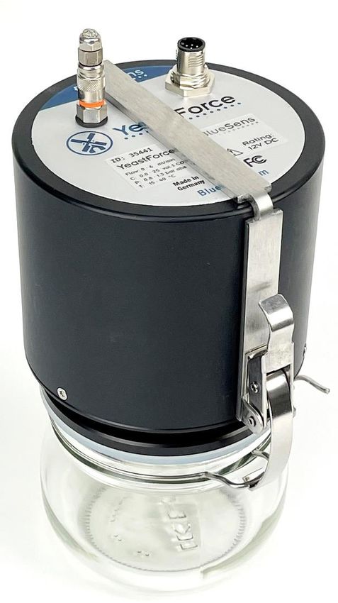
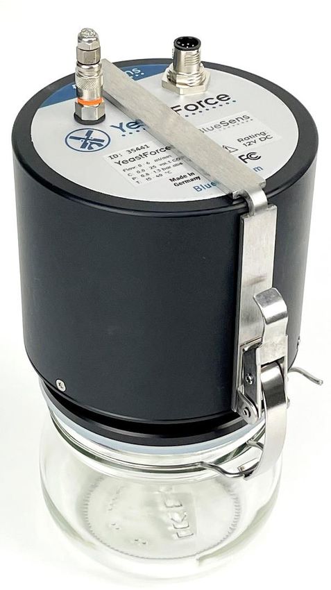
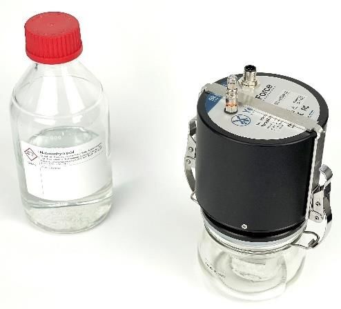
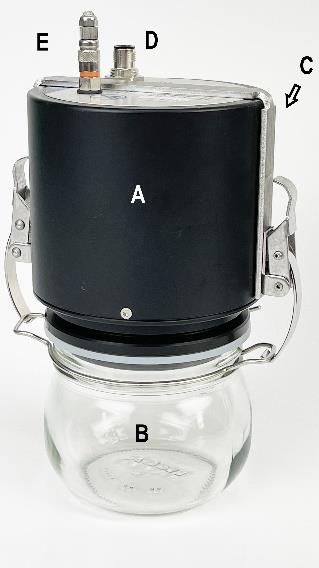
OPERATING MANUAL EN 3 Product description The sensor The YeastForce consists of a sensor top section [A] (with sensors for pressure, CO2 concentration and temperature) and a lower section consisting of a jar [B] with one bracket [C]. There are two connectors on the top of the YeastForce. One connection is used for the power supply and communications [D]. The other connec- tion is used for the gas discharge [E]. A filter is in- cluded for the gas discharge. Figure 1 During operations, the filter must be mounted at the gas discharge outlet. Otherwise, the pressure cannot be released from the sensor. This would prevent the sensor from functioning correctly; dangerous over- pressure could then occur. To achieve the best measurement result, the YeastForce should be operated in a bath of water at a constant temperature while measuring. The water level must not be higher than the glass jar. Converting to a standardized gas The YeastForce has sensors for pressure and tem- perature. With the help of these measured values, the internally calculated volume is normalized to the standard conditions of 1013.25 mbar and 273.15 K (0°C). The calculation can be converted back to any labor- atory conditions by using the general gas equation. Since the number of particles in a closed system is constant, the following formula applies: ∗ = where = [ ] = [ ] = [ ] In the template settings of the YeastForce Monitor, you can set the standard conditions for the tempera- ture to easily compare it with other measuring meth- ods according to user requirements. Rev 220301 003 6

OPERATING MANUAL EN Accessories The following accessories are required for the ini- tial commissioning of the YeastForce: 3.3.1 USB RS232 serial port adapter with power supply connection (Z-KA-00014) With wrap-around (refer to chapter 5.2) Figure 2. Connection from the PC (USB) to the YeastForce (M12 / 8-pin) 3.3.2 12 V DC power supply (Z-NT-00010) Figure 3. 12 V DC power supply 3.3.3 Glass jar for the YeastForce Standard empty volume of 562.5 ml (± 2 ml) (Z-GF-00019) Figure 4 Glass jar for the YeastForce 3.3.4 Bracket for the YeastForce (Z-XX-00166) Figure 5 Bracket 3.3.5 Filter adapter for the YeastForce gas discharge (Z-XX-00133) Figure 6 Filter adapter Rev 220301 003 7
OPERATING MANUAL EN

3.3.6 Piston pump for volume inspection (20
 ml)

 (Z-XX-00134)
 Figure 7 Piston pump

3.3.7 Active USB hub

 Optional
 (K-00006)
 Figure 8 Active USB hub

3.3.8 Seal ring

 (Z-XX-00200)

 Figure 9 Seal Ring

 Required laboratory materials

3.4.1 Sodium hydroxide NaOH
For removing residual CO2 during the single-point Available from chemical specialty stores
calibration of the CO2 sensor

3.4.2 Water bath
 Water height: 5 – 9 cm (maximum height of glass
The sensor is calibrated to a temperature range of
 jar)
15-40°C. Therefore the water bath may have a tem-
 The YeastForce must not be completely im-
perature range of 25-40°C.
 mersed because it has a protection class of IP64!

Rev 220301 003 8
OPERATING MANUAL EN

4 Installation
 General instructions
During delivery, the YeastForce has been shipped in
protective packaging. This packaging protects
against normal transport loads. Nevertheless, please
check before installation whether the device has
been damaged by improper transport or improper
storage. Safe operation is not possible if the device
is damaged. The device may not be installed or put
into operation if damage is detected.
Make sure that the specified operating conditions are
maintained at all times.
Installation should only be carried out under expert
guidance and in accordance with the relevant recog-
nized occupational safety regulations.

 Attaching the filter adapter

 Important!

 If the sensor is supplied without a filter adapter on
 the gas discharge, the filter adapter must be at-
 tached to the gas discharge after unpacking the
 YeastForce sensors.

 Figure 10 Attaching the filter adapter

 Rev 220301 003 9
OPERATING MANUAL EN 5 Electrical connection In general Caution! Read the installation instructions carefully to avoid damaging this device. Proceed step by step. Use only the original plugs, cables and power supplies. Never connect or disconnect the plug when the device is connected to the power supply. This device has no on/off switch. It starts op- erating immediately after it is connected to the power supply. Incorrect operations may damage the device. USB - RS232 cable wrap-around To minimize the risk that the YeastForce cable tangles with any other cables, the power supply cable should be wrapped around the data cable. A simple method is to wrap the power supply cable around the data cable. First, wrap the data cable around the M12 8-pin connector. Continue until the power supply cable is completely wrapped around the data cable. Figure 11 Wrapping the cables At the end, make a small loop and form the cable into a knot. This prevents the power cable from un- winding. Figure 12 Knot the cables at the end RS232 connection to the PC The USB-to-RS232 cable (with power supply) is first attached to the YeastForce using the M12 8- pin adapter. The plug of the power supply unit is then connected to the power connection of the data cable and se- cured so that it cannot slip out. Figure 13 Rev 220301 003 10
OPERATING MANUAL EN The power supply unit may now be plugged into a power outlet. Now, the sensor starts working. The cable's USB plug should now be connected to a computer (in an active hub if necessary). Figure 14 The sensor needs about one hour un- til it is ready for operations. No meas- urement may be made before this. The YeastForce Monitor program shows a flash- ing icon during this warm-up period: [Wait while sensor heats up] Figure 15 Rev 220301 003 11
OPERATING MANUAL EN 6 YeastForce Monitor You can download the latest software at the following link: https://www.bluesens.com/fileadmin/user_upload/downloads/YeastForceMonitorSetup_1_4_20.msi Installing the software Double-click on the .msi file to start the installa- tion. Since the program is installed in the Program Files folder, admin rights are required during in- stallation. The Welcome page appears. Click on [Next] Figure 16 Select the installation path and user settings. Click on [Next] Figure 17 Confirm and start the installation: Click on [Next] Figure 18 Rev 220301 003 12
OPERATING MANUAL EN The program is installed: Please wait: A progress bar shows the installation progress. Figure 19 The final dialogue box appears after a successful installation: Click on [Close] Figure 20 Rev 220301 003 13
OPERATING MANUAL EN Connecting the sensors If the drivers are not found automatically, you can download the latest FTDI-VCP driver from the follow- ing page: https://www.ftdichip.com/Drivers/VCP.htm Search for heads: Figure 21 YeastForce Monitor, after the program start When the program is started, all available COM ports in the computer are scanned for connected sensors. These are then loaded into the program. If not all sensors are found, the program can search for more sensors again via the [HeadsSearch Heads] option. Figure 22 If a found sensor is then disconnected and recon- nected to the computer, it can be reactivated with the [Reconnect] option. Figure 23 Rev 220301 003 14
OPERATING MANUAL EN

6.3.1 Configuring a sensor head

 To configure the YeastForce sensor, the
 Configuration window can be invoked from
 the [Heads] menu or the [HeadInfo] right-
 click context menu.

 Figure 24

 Use the [Custom Head Color] drop-down
 list to change the display colour of the sen-
 sor.

 The [Show Always] option causes the sen-
 sor to always be displayed on the user in-
 terface. If the sensor is not found, this is
 displayed immediately. You can reactivate
 the sensor in the program's context menu Figure 25
 via [Reconnect].
 If the [Show Export Options / Calibration]
 option is selected, additional information
 about the sensor is displayed.

 This calibration information relates to the
 data about the operating status saved in
 the sensor or the program. If the single-
 point calibration or volume inspection was
 performed more than one month ago, it
 must be carried out again. The previous
 dates (of last execution) are displayed in
 this window.

 Figure 26

 Rev 220301 003 15
OPERATING MANUAL EN CO2 sensor: single-point calibration CO2 absorber NaOH Danger! Serious injury to skin or eyes NaOH may only be used in accord- ance with the applicable safety pre- Wear protective gloves cautions! Wear safety goggles Gather the materials together: - YeastForce sensor - Glass jar for the YeastForce - NaOH solution (e.g. 3 M ~= 10 %) - Small vessel for at least 20 ml NaOH (e.g. 100 ml beaker), which will fit into the glass jar Figure 27 Pour 20 to 100 ml NaOH into a suitable vessel and place it in the glass jar. Figure 28 Attach the YeastForce to the jar using the bracket on the glass jar. Figure 29 Rev 220301 003 16
OPERATING MANUAL EN

Start the single-point calibration in the YeastForce
Monitor (via the right-click context menu for the
sensor and confirm the information about the ad-
dition of NaOH by clicking on OK).

 Figure 30

The concentration is then recorded for 5 minutes
and the slope of the graph is displayed. The upper
graph shows the progress over the entire time of
the measurement. The lower graph always shows
only the last five minutes. The slope of the graph
is also calculated during these five minutes.

 Figure 31

The CO2 concentration now decreases until there
are hardly any CO2 molecules left in the vessel. If
the slope drops below 2 ppm/min, the button for
the single-point is enabled.

 Figure 32

After the single-point calibration is finished, the
new concentration for the sensor is displayed. If
this is more than 0.01% by volume, the single-
point calibration should be performed again.

 Figure 33

Rev 220301 003 17
OPERATING MANUAL EN

Click on the Restart button: the instrument waits
again for 5 minutes until a new single-point cali-
bration is possible.
Also here, the slope must be less than 2 ppm/min.

 Figure 34

You can click on the [Return to YeastForce Moni-
tor] button to return to the main program.

 Figure 35

Rev 220301 003 18
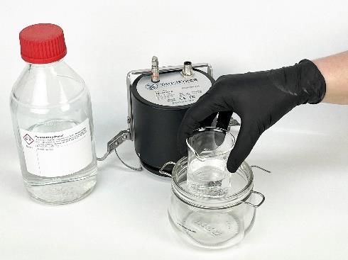
OPERATING MANUAL EN Volume inspection (Refer to chapter 5) Connect the sensor to the power supply. Connect the USB cable to the computer. Mount the YeastForce on a glass jar. Place them together in a water bath with a water height be- tween 5 and 9 cm. The temperature in the water bath should be be- tween 25 and 40 °C, and higher than room tem- perature. Keep the water bath and sensor at a constant temperature for at least 30 minutes. Figure 36 Start the YeastForce Monitor software program (Refer to chapter 6.3 Search for heads) and search for the connected YeastForce head. Start a volume inspection from the right-click con- text menu. Figure 37 Pull out the piston pump. Figure 38 Remove the YeastForce's protective filter by pushing the fluted ring down towards the orange band. Figure 39 Enter the temperature of the piston in the pro- gram. (here: 27.5°C) If it is too cold, heat the piston to 20°C with your hands. Figure 40 Rev 220301 003 19
OPERATING MANUAL EN

Place the piston pump on the YeastForce until
the piston clicks into place.

Then, confirm this in the program:
[OK – Piston connected]

 Figure 41

Wait about 10 seconds.

If the pressure is constant and the program
prompts you to do so, press the piston rod into the
piston slowly and consistently.

 Figure 42

After the valve closes (audible soft click and the
message [Remove Piston]), the piston can be re-
moved and the filter can be put on.

 Figure 43

The pressure rises in the YeastForce.
The program records the pressure and calculates
the tightness and volume of the system.

The lower graph shows a partial section of the up-
per graph.
This automatically displays the relevant part of the
measurement with more details.

 Figure 44

Rev 220301 003 20
OPERATING MANUAL EN

After about 5 minutes, the calculation is com-
pleted and the results are displayed in a window.

 Figure 45

Click on the button [Show/Hide Details] to display
the individual values of the calculation.

If the calculation was not successful, the inspec-
tion can be repeated by clicking the [Retry] button.

 Figure 46

If the filter connector is not plugged back into the
gas discharge, the sensor will report a message.
The measurement should then be repeated to
check the return for external pressure.

 Figure 47

Rev 220301 003 21
OPERATING MANUAL EN

 Preparing a measurement

6.6.1 Preparing a template

Figure 48

 A template for a measurement can be configured
 for each type of dough.
 The template configuration opens when you click
 on the context menu of a template field:

 Figure 49

 The volume of the glass jar and the volume of the
 dough are recorded with an accuracy of ± 2 ml
 when possible.

 The total volume (Total [ml]) of the system
 >>YeastForce Sensor + jar
OPERATING MANUAL EN

The selection options can be changed, created or
deleted by the user with the [ Or ]
menu option.

 Figure 51

The measurement duration, the logging interval
and the calculation temperature can be set in
Measurement Options. A start delay is currently
deactivated. The calculation temperature allows
the standard temperature to be set to a different
temperature so that a better comparison can be
made with other measuring methods.
The [Log Raw Data] option may be enabled so that
the data can be subsequently evaluated by Blue-
Sens. This means that all information received by Figure 52
the program every second is saved in a separate
file.

You can create separate settings for the report for
each template.
The [Summary Interval] indicates the time interval
for the measured values in the summary. The dis-
play of the graphs can be changed so that the
dough volume and the gas holding capacity are not
shown.
The [Create PDF] option causes the report to be
saved as a PDF file in the Reports folder.
 Figure 53
The key information for each measurement is nor-
mally stored in a report log in .csv format. If the cor-
responding option is not selected, no entry is cre-
ated.

The user may specify a default comment. There
are two options for this:
The [Use Default Comment] option ensures that
the specified comment is added to the sensor in-
formation when the template is selected.
If the upper option is selected, the measurement Figure 54
cannot be started until the user has changed the
comment (e.g. to enter additional information such
as a batch number).

Rev 220301 003 23
OPERATING MANUAL EN

6.6.2 German-English translations
 Lagerung/Herkunft Storage/Origin
 frisch fresh
 1T35°C 1T35°C
 Eigenes Rückstellmuster own samples
 Kundenmuster customer sample
 Gefroren frozen
 sonstige other

 Teigart Dough Type
 Standard standard
 Zucker sugar
 sonstige other

 Konfektionsform Packaging
 Nutsche strainer
 Trennsepariert/Flüssig ungewaschen separated/liquid unwashed
 Flüssig gewaschen liquid washed
 Pfund pound
 Block block
 Beutel bag
 Sonstige other

 Verdünnung Dilution
 Vor Verdünnung Pre dilution
 Nach Verdünnung Post dilution
 Keine Verdünnung No dilution
 Nicht zutreffend Not applicable

The user may edit each entry and add user-defined
entries.

 Rev 220301 003 24
OPERATING MANUAL EN 6.6.3 Creating a new template There are three different methods to create a tem- plate in the program: Via the right-click context menu for a template, an existing template can be copied to a new template [Copy Into New Template]. You only need to spec- ify a new name. Then, the template can be changed to fit your requirements. Figure 55 Click on the menu option [TemplatesNew] to create a new template with standard settings. A template can be loaded from a template*.xml file by selecting the menu option [TemplatesLoad]. Information on exchanging templates can be ob- tained from BlueSens. Figure 56 Rev 220301 003 25
OPERATING MANUAL EN

 Starting a measurement
Before starting a measurement, a template must
first be selected in the [Selection] tab. A selected
template is then framed in the colour of the sensor.

 Figure 57

As soon as a template field is selected, the cursor
jumps to the comment field. The comment may be
changed but must not be empty.

 Figure 58

If error messages are present, no new measure-
ment can be started. If an attempt is made to start
a measurement nevertheless, an error message is
displayed.

 Figure 59

When there is no error message, the measure-
ment can be started by clicking on the Start sym-
bol.

The Start symbol is then disabled and the Stop
symbol is enabled.
 Figure 60

After a measurement is started, the [Chart] tab is
enabled and the graph of the volume produced is
displayed.
The display for the [dough volume] and [gas reten-
tion] can be selected from tabs at the bottom.

Rev 220301 003 26
OPERATING MANUAL EN 6.7.1 Status icons Icon 2 (for [Error Text] Information Icon GIFs) [Wait while sensor heats up] Wait until the sensor has heated up. This is displayed for approx. 1 hour after connecting the sen- sor to the power supply. [Signal too low for measuring] The sensor signal is too low. If this error does not disappear within 20 minutes, the sensor lamp may be defective. Please contact the service department. [The Last Volume Inspection has not been successful] The previous volume inspection was not successful. Please repeat the volume inspection. (refer to 6.5) [The last Volume Inspection dates back more than one month] The last volume inspection was made more than a month ago. Please carry out a volume inspection: (refer to 6.5) [The last 1Point Calibration dates back more than one month] The last single-point calibration was made more than a month ago. Please carry out a single-point calibration: (refer to 6.4) [The Connection to the Sensor is Lost] The connection to the sensor is no longer established. Check the data cable and power supply. The concentration is too high to start the measurement. Please flush the sensor out with fresh air. (This appears as long as the concentration in the sensor at (rotating) the start of the measurement is > 0.5 vol.-% CO2 ) Rinse sensor with fresh air = Place sensor on its side. If that is inadequate: Single-point calibration? Open the report PDF file of the previous measurement Open the report log file in csv format Rev 220301 003 27
OPERATING MANUAL EN

7 Appendix
 Technical data

 Number of measuring channels 3: CO2, pressure, temperature
 Measuring method for CO2 Two infra-red wavelengths
 Pressure range 0.8 – 1.3 bar
 Accuracy < 0.2 % full scale ± 3 % reading
 Measuring range for CO2 25 % by volume
 Measurable gas volume flow 0 – 360 ml/h in 500 ml sample vessel
 Resolution for volume and CO2 V= 0.01 ml; C = 0.005 vol.%
 Dimensions ø 115 x 205 mm
 Temperature range 15 – 40 °C
 Ambient humidity < 90 %
 Housing IP64
 PC connection USB
 Measuring interval 1 s (internal),
 Logging interval (default) 10 s,
 Summary interval
 (default) 10 min
 Electrical supply 12 V DC via power supply unit (included)
 Requirements for the PC 8 GB of RAM,
 Operating system: Win7 64 bit or later,
 One USB2 port,
 Display resolution > 1280 x 800 px
 Software YeastForce Monitor
 Sample weight Depending on the size of the sample vessel,
 Volume ratio 1:10
 Size of the sample vessel 10 times larger than dough sample/volume

 Warranty

The warranty period for YeastForce is stated in our terms and conditions.

 A loss of the warranty is likely to be caused by non-observance of these operating instruc-
 tions, in case of improper handling (e.g. opening the YeastForce) and when using an other
 than the supplied original power supply.

 Service and Support

Our qualified customer service will be happy to assist you as a partner.
If necessary, please contact your distributor or directly to us:
Tel.: +49 2366 4995 567 or via e-mail service@bluesens.de
USA: 847 201 3124 or via e-mail service@bluesens.com

 Rev 220301 003 28
OPERATING MANUAL EN

 Proper disposal

We recommend sending back old or broken YeastForce to BlueSens gas sensor GmbH (address see
under "imprint"). We will then guarantee you a professional decomposition and environmentally compati-
ble recycling of all components!

 Imprint

YeastForce Operating Manual English
Edition Rev.220301 003
© BlueSens gas sensor GmbH
The pictures and drawings in this manual may differ from the original, they are only for illustration pur-
poses. All specifications – including technical specifications – can be changed without notice. All pictures
and graphics in this guide: © BlueSens gas sensor GmbH, Herten

BlueSens gas sensor GmbH
Snirgelskamp 25
D-45699 Herten, Germany
Phone +049 (0)2366/4995500
Fax +049 (0)2366/4995599
E-mail: service@bluesens.de
- State of information: March 2022 –

 Rev 220301 003 29
OPERATING MANUAL EN

8 CE-CONFORMITY

EU Declaration of Conformity according
EU Directive 2014/30/EU (EMC - Directive)
EU Directive 2011/65/EU (RoHS-Directive)

We, BlueSens gas sensor GmbH
Snirgelskamp 25, 45699 Herten (Germany)
herewith declare in sole responsibility that the product:

Sensor
YeastForce

In combination with our accessories:
Power supply,
Cables

observe the essential requirements determined in the Council Directive for
the adoption of the legal regulations of the Member States about electro-
magnetic compatibility (2014/30/EU).

The judgement of the product to electromagnetic compatibility was effected
on basis of the following EC harmonised standards:
 EMI EN 55011
 EMS EN 61326-1

This declaration applies to all specimen manufactured according to the
sample tested.

HERTEN, 20.10.2019
Place and Date Countersign of manufacturer/rep-
resentative

 Rev 220301 003 30
OPERATING MANUAL EN

9 FCC-CONFORMITY

Declaration of Conformity
We, BlueSens gas sensor GmbH
Snirgelskamp 25, 45699 Herten (Germany)
herewith declare in sole responsibility that the prod-
uct:

Sensor
YeastForce

In combination with our accessories:
Power supply,
Cables

To which this declaration relates is in conformity with the following specifications:
FCC 47 CFR, 15B, §15.107 & §15.109

This declaration applies to all specimen manufactured according to the sample tested.

This device complies with Part 15 of the FCC Rules. Operation is subject to the following two conditions:
(1) this device may not cause harmful interference, and (2) this device must accept any interference re-
ceived, including interference that may cause undesired operation.

HERTEN, 20.10.2019
Place and Date Countersign of manufacturer/representative

 Rev 220301 003 31
BETRIEBSANLEITUNG DE

Betriebsanleitung

Rev 220301 003
BETRIEBSANLEITUNG DE

Inhalt
1 ZU DIESEM DOKUMENT............................................................................................... 34
 Funktion .................................................................................................................................. 34
 Zielgruppe .............................................................................................................................. 34
 Benutzte Symbole .................................................................................................................. 34
2 ZU IHRER SICHERHEIT ................................................................................................ 35
 Allgemeines ............................................................................................................................ 35
 Autorisiertes Personal ............................................................................................................ 35
 Bestimmungsgemäße Verwendung ....................................................................................... 35
 Warnung vor Fehlgebrauch .................................................................................................... 36
 Allgemeine Sicherheitshinweise ............................................................................................. 36
 CE Konformität ....................................................................................................................... 36
3 PRODUKTBESCHREIBUNG ......................................................................................... 37
 Der Sensor ............................................................................................................................. 37
 Umrechnung auf Normgas ..................................................................................................... 37
 Zubehör .................................................................................................................................. 38
 Benötigte Labormaterialien .................................................................................................... 39
4 INSTALLATION .............................................................................................................. 40
 Allgemeine Instruktionen ........................................................................................................ 40
 Filteradapter aufsetzen........................................................................................................... 40
5 ELEKTRISCHER ANSCHLUSS ..................................................................................... 41
 Allgemeines ............................................................................................................................ 41
 Verwicklung USB-To-RS232 Kabel........................................................................................ 41
 Anschluss RS232 an PC ........................................................................................................ 41
6 YEASTFORCE MONITOR ............................................................................................. 43
 Installation Software ............................................................................................................... 43
 Anschließen der Sensoren ..................................................................................................... 45
 Köpfe suchen: ........................................................................................................................ 45
 CO2 Sensor – 1Punkt Kalibration ........................................................................................... 47
 Volumen Inspektion ................................................................................................................ 50
 Messung vorbereiten .............................................................................................................. 53
 Messung starten ..................................................................................................................... 57
7 ANHANG ........................................................................................................................ 59
 Technische Daten .................................................................................................................. 59
 Gewährleistung ...................................................................................................................... 59
 Service und Support ............................................................................................................... 59
 Ordnungsgemäße Entsorgung ............................................................................................... 60
 Impressum .............................................................................................................................. 60
8 CE-KONFORMITÄT ....................................................................................................... 61
9 FCC-KONFORMITÄT ..................................................................................................... 62

 Rev 220301 003 33
BETRIEBSANLEITUNG DE 1 Zu diesem Dokument Funktion Die vorliegende Betriebsanleitung liefert Ihnen alle erforderlichen Informati- onen für eine schnelle Inbetriebnahme und einen sicheren Betrieb des YeastForce. Lesen Sie diese Betriebsanleitung deshalb vor Inbetrieb- nahme. Bewahren Sie diese Betriebsanleitung für den späteren Gebrauch sicher auf. Zielgruppe Diese Betriebsanleitung richtet sich an ausgebildetes Fachpersonal. Der In- halt dieser Anleitung muss dem Fachpersonal zugänglich gemacht und um- gesetzt werden. Benutzte Symbole Gefahr! Dieses Symbol weist auf eine mögliche und gefährliche Situation hin. Nichtbeachten dieses Sicherheitshinweises kann Personen- schäden zur Folge haben. Vorsicht! Dieses Symbol weist auf eine mögliche Sachbeschädigung hin. Hinweis! Dieses Symbol kennzeichnet hilfreiche Zusatzinformationen. 1 Handlungsfolge Vorangestellte Zahlen kennzeichnen aufeinander folgende Handlungsschritte. Rev 220301 003 34
BETRIEBSANLEITUNG DE

2 Zu Ihrer Sicherheit
 Allgemeines
Der YeastForce hat unser Werk in geprüftem und betriebsbereitem Zustand
verlassen.
Bitte lesen Sie vor Montage und Inbetriebnahme des Gerätes diese Betriebs-
anleitung sorgfältig durch. Die Betriebsanleitung beinhaltet Sicherheitshin-
weise, die beachtet werden müssen, um einen gefahrlosen Betrieb zu ge-
währleisten.
Der Inhalt dieser Bedienungsanleitung entspricht dem Bearbeitungsstand
von November 2020 und kann ohne vorherige Ankündigung geändert wer-
den. Technische Änderungen im Zuge der Weiterentwicklung bleiben vorbe-
halten.
Die Richtigkeit der Informationen in dieser Bedienanleitung wurde sorgfältig
geprüft. Ungeachtet dessen übernimmt die BlueSens gas sensor GmbH
keine Haftung für Folgen, die aus Fehlern in der Beschreibung und den Ab-
bildungen entstehen. Es gelten die AGB der BlueSens gas sensor GmbH.
Das Gerät darf niemals unter Bedingungen betrieben werden, die nicht den
angegebenen Spezifikationen und den Angaben auf dem Typenschild ent-
sprechen.
Wartung und Instandsetzung darf nur von sach- und fachkundig geschulten
Personen vorgenommen werden, die mit den damit verbundenen Gefahren
und Garantiebestimmungen vertraut sind.
 Autorisiertes Personal
Sämtliche in dieser Betriebsanleitung beschriebenen Handhabungen dürfen
ausschließlich durch ausgebildetes und vom Anlagenbetreiber autorisiertes
Fachpersonal durchgeführt werden. Darüber hinaus gehende Eingriffe in das
Gerät dürfen aus Sicherheits- und Gewährleistungsgründen nur durch Per-
sonal der BlueSens gas sensor GmbH vorgenommen werden.
 Bestimmungsgemäße Verwendung
Der YeastForce ist, wie in den Technischen Daten beschrieben, ein Gerät
zur Messung von Volumenströmen im angegeben Durchflussbereich und un-
ter den Bedingungen. Es dient zur Überwachung von Stoffwechselvorgän-
gen biologischer Prozesse. Das Messgerät YeastForce darf nur in gut be-
lüfteten Räumen eingesetzt werden.

 Rev 220301 003 35
BETRIEBSANLEITUNG DE

 Gefahr!
Das Messgerät hat keine Zulassung nach ATEX und darf daher nur in
gut belüfteten Räumen eingesetzt werden.

 Warnung vor Fehlgebrauch
Der YeastForce darf nicht als Sicherheitsbauteil zur Überwachung in An-
lagen eingesetzt werden, er darf nicht in Explosionszonen eingesetzt wer-
den.
 Allgemeine Sicherheitshinweise
Bei nicht sachgerechter oder nicht bestimmungsgemäßer Verwendung
können von diesem Gerät anwendungsspezifische Gefahren ausgehen.

 Gefahr!
Durch falsche Montage oder Einstellung besteht Explosionsgefahr.
Überprüfen Sie alle Anschlüsse nach der Montage auf Dichtigkeit.

 CE Konformität
Der YeastForce ist konform mit der EMV-Richtlinie (2014/30/EU) unter An-
wendung der harmonisierten Normen EN 55011, EN 61326-1.
Die Niederspannungsrichtlinie (2014/35/EU) findet keine Anwendung, da
keine Spannung größer 24V genutzt wird.
Das CE- und FCC-Zertifikat finden Sie auf den letzten Seiten dieser Bedie-
nungsanleitung.

 Rev 220301 003 36
BETRIEBSANLEITUNG DE 3 Produktbeschreibung Der Sensor Der YeastForce besteht aus einem Sensoroberteil mit Sensorik [A] für Druck, CO2 Konzentration und Temperatur sowie einem Glas [B] mit einem Bügel [C] als Sensorunterteil. Auf der Oberseite des YeastForce sind zwei An- schlüsse vorhanden. Ein Anschluss dient zur Stromversorgung und Kommunikation [D], der an- dere Anschluss dient zum Gasablass [E]. Für den Gasablass ist ein Filter beigelegt. Abbildung 1 Im Betrieb muss der Filter auf dem Gasauslass angebracht sein, da an- sonsten der Druck nicht aus dem Sensor abgelassen werden kann. Die korrekte Funktion des Sensors ist ansonsten nicht gegeben und es kann zu gefährlichen Überdrücken kommen. Um ein optimales Messergebnis zu erzielen, sollte der YeastForce während der Messung in einem Wasserbad bei konstanter Temperatur betrieben werden. Der Wasserstand darf hierbei nicht über das Glas hinaus gehen Umrechnung auf Normgas Der YeastForce enthält Sensoren für Druck und Temperatur. Mithilfe dieser Messwerte wird das in- tern berechnete Volumen auf Normalbedingungen von 1013,25 mbar und 273,15 K (0°C) normiert. Die Berechnung kann über die allgemeine Gasglei- chung auf beliebige Laborbedingungen zurückge- führt werden. Da im geschlossenen System die Teil- chenanzahl konstant ist, gilt die Formel ∗ = mit = [ ] = [ ] = [ ] In den Template-Einstellungen von YeastForce Mo- nitor ist es möglich die Normbedingungen für die Temperatur zum einfacheren Vergleich mit anderen Messmethoden nach Benutzerwünschen einzustel- len. Rev 220301 003 37
BETRIEBSANLEITUNG DE Zubehör Zur Inbetriebnahme eines YeastForce wird folgen- des Zubehör benötigt: 3.3.1 USB RS232 Serial Port Adapter mit Anschluss für Spannungsversorgung (Z-KA-00014) Mit Verwicklung (siehe Kapitel 5.2) Abbildung 2. Verbindung vom PC (USB) zum YeastForce (M12- 8 pol.) 3.3.2 DC Spannungsversorgung 12V (Z-NT-00010) Abbildung 3. Spannungsversorgung 12V DC 3.3.3 Glas für YeastForce Standard-Leervolumen 562,5 ml ± 2ml (Z-GF-00019) Abbildung 4. Glas für YeastForce 3.3.4 Haltebügel für YeastForce (Z-XX-00166) Abbildung 5 3.3.5 Filteradapter für YeastForce Gasauslass (Z-XX-00133) Abbildung 6 Filteradapter Rev 220301 003 38
BETRIEBSANLEITUNG DE

3.3.6 Kolbenpumpe für Volumeninspektion
 20ml

 (Z-XX-00134
 Abbildung 7 Kolbenpumpe

3.3.7 Aktiver USB-Hub

 Optional
 (K-00006)
 Abbildung 8 Aktiver USB-Hub

3.3.8 Dichtungsring

 (Z-XX-00200)

 Abbildung 9 Dichtungsring

 Benötigte Labormaterialien

3.4.1 Natriumhydroxid NaOH
Zum Entfernen von CO2 Resten bei der 1Punkt Ka- Erhältlich im Chemiefachhandel
libration des CO2 Sensors

3.4.2 Wasserbad
Mit einem Temperaturbereich im Bereich 25-40°C Wasserhöhe 5 – 9 cm (maximal Glashöhe)
Der Sensor ist auf eine Temperatur von 15-40°C ka- da der YeastForce eine Schutzklasse IP64 hat
libriert. darf er nicht eintauchen!

Rev 220301 003 39
BETRIEBSANLEITUNG DE

4 Installation
 Allgemeine Instruktionen
Der YeastForce wurde auf dem Weg zum Einsatzort
durch eine Verpackung geschützt. Dabei sind die üb-
lichen Transportbeanspruchungen abgesichert. Prü-
fen Sie dennoch vor der Installation, ob das Gerät
durch unsachgemäßen Transport oder unsachge-
mäße Lagerung beschädigt worden ist. Bei eventuel-
len Beschädigungen ist ein gefahrloser Betrieb nicht
möglich, das Gerät darf nicht installiert und in Betrieb
genommen werden.
Beachten Sie, dass die Betriebsbedingungen zu je-
der Zeit eingehalten werden.
Der Einbau sollte ausschließlich unter fachmänni-
scher Anleitung und unter Berücksichtigung der ent-
sprechenden anerkannten Regeln für Arbeitssicher-
heit erfolgen.

 Filteradapter aufsetzen
 Wichtig!

 Wenn der Sensor ohne Filteradapter auf dem Gas-
 auslass geliefert wird, muss der Filteradapter nach
 dem Auspacken der YeastForce Sensoren auf
 den Gasauslass aufgesetzt werden.

 Abbildung 10 Filteradapter aufsetzen

 Rev 220301 003 40
BETRIEBSANLEITUNG DE

5 Elektrischer Anschluss
 Allgemeines

 Vorsicht!
Lesen Sie die Installationshinweise sorgfältig, um
Schäden am Gerät zu vermeiden.
Gehen Sie schrittweise vor.
Benutzen Sie nur die originalen Stecker, Kabel und
Netzgeräte.
Niemals Stecker anstecken oder abziehen, wenn
das Gerät an die Spannungsversorgung ange-
schlossen ist.
Das Gerät hat keinen Ein/Aus-Schalter, es ist direkt
nach Anschluss an die Spannungsversorgung in
Betrieb.
Fehlbedienung kann zu Schäden am Gerät führen.

 Verwicklung USB-To-RS232 Kabel
 Damit das Kabel am YeastForce sich weniger mit
 möglicherweise anderen vorhandenen Kabeln ver-
 knotet, sollte das Kabel der Spannungsversorgung
 mit dem Datenkabel verbunden werden. Eine ein-
 fache Methode dafür ist das Umwickeln des Da-
 tenkabels mit dem Kabel der Spannungsversor-
 gung.
 Zunächst am M12 8-Pol Anschluss anfangen das
 Datenkabel zu umwickeln. Fortführen bis das Ka-
 bel der Spannungsversorgung komplett um das Abbildung 11 Verdrillung des Kabels
 Datenkabel gewickelt ist.
 Am Schluss eine kleine Schlaufe bilden und das
 Kabel zu einem Knoten formen. Damit wird verhin-
 dert, dass sich das Stromkabel wieder entwindet.

 Abbildung 12 Zum Schluss einen kleinen Knoten bilden
 Anschluss RS232 an PC
 Das USB-To-RS232 Kabel mit Spannungsversor-
 gung wird erst mit dem M12-8pol Adapter am
 YeastForce befestigt.

 Der Stecker des Netzteils wird mit dem Stroman-
 schluss des Datenkabels verbunden und gegen
 Herausrutschen gesichert.

 Abbildung 13
 Das Netzteil darf nun in eine Steckdose gesteckt
 werden. Der Sensor ist nun angeschaltet.

 Rev 220301 003 41
BETRIEBSANLEITUNG DE Der USB-Stecker des Kabels kann nun mit einem Computer (ggf. in einem aktiven Hub) verbunden werden. Abbildung 14 Der Sensor benötigt ca. 1h bis er Be- triebsbereit ist. Vorher kann keine Mes- sung durchgeführt werden. Das Programm YeastForce Monitor zeigt in die- ser Aufwärmzeit ein blinkendes Icon: [Wait while Sensor heats up] Abbildung 15 Rev 220301 003 42
BETRIEBSANLEITUNG DE 6 YeastForce Monitor Die aktuelle Software erhalten Sie über folgenden Link: https://www.bluesens.com/fileadmin/user_upload/downloads/YeastForceMonitorSetup_1_4_20.msi Installation Software Durch einen Doppelklick auf die .msi Datei wird die Installation gestartet. Da das Programm im Ordner Program Files installiert wird, werden während der Installation Admin-Rechte benötigt. Es öffnet sich die Willkommens-Seite. Klick auf [Next] Abbildung 16 Auswahl des Installationspfades und Benutzer- Einstellung. Klick auf [Next] Abbildung 17 Bestätigung und Start der Installation durch: Klick auf [Next] Abbildung 18 Rev 220301 003 43
BETRIEBSANLEITUNG DE Das Programm wird installiert: Bitte warten: Ein Fortschrittsbalken zeigt den Installationsfortschritt an. Abbildung 19 Nach erfolgreicher Installation erscheint noch der Abschluss-Dialog: Klick auf [Close] Abbildung 20 Rev 220301 003 44
BETRIEBSANLEITUNG DE Anschließen der Sensoren Wenn die Treiber nicht automatisch gefunden wer- den, kann man den aktuellen FTDI-VCP Treiber auf der folgenden Seite herunterladen: https://www.ftdichip.com/Drivers/VCP.htm Köpfe suchen: Abbildung 21 YeastForce Monitor, nach dem Programm Start Bei Starten des Programmes werden alle verfüg- baren COM-Ports des Rechners nach angeschlos- senen Sensoren gescannt und diese anschlie- ßend in das Programm geladen. Wenn dabei nicht alle Sensoren gefunden werden, kann das Programm über [HeadsSearch Heads] erneut nach weiteren Sensoren suchen. Abbildung 22 Sollte ein bereits gefundener Sensor zwischen- zeitlich vom Rechner getrennt worden sein, kann dieser nach dem erneuten Verbinden über den Kontext [Reconnect] wieder aktiviert werden. Abbildung 23 Rev 220301 003 45
BETRIEBSANLEITUNG DE

6.3.1 Sensor-Kopf einrichten

 Zum Einstellen des YeastForce Sensors
 kann über das [Heads] Menu bzw. über
 das [HeadInfo Kontext-Menu via Rechts-
 klick] das Konfigurationsfenster aufgeru-
 fen werden.

 Abbildung 24

 Über die Dropdown-Liste [Custom Head
 Color] kann die Anzeige-Farbe des Sen-
 sors geändert werden.

 Die Option [Show Always] bewirkt, dass
 der Sensor immer auf der Benutzerober-
 fläche angezeigt wird. Wird der Sensor
 nicht gefunden, sieht man dies sofort und
 kann den Sensor über sein Kontext-Menu Abbildung 25
 über [Reconnect] wieder im Programm
 aktivieren.
 Wird die Option [Show Export Options /
 Calibration] ausgewählt, werden zusätzli-
 che Informationen über den Sensor ange-
 zeigt.

 Die Informationen geben die im Sensor,
 bzw. im Programm gespeicherten Daten
 zum Betriebszustand aus. Wenn die
 1Punkt Kalibration oder die Volumenin-
 spektion mehr als einen Monat her ist,
 muss dies jeweils erneut ausgeführt wer-
 den. Über dieses Fenster ist das Datum
 der letzten Ausführung auszulesen.

 Abbildung 26

 Rev 220301 003 46
BETRIEBSANLEITUNG DE CO2 Sensor – 1Punkt Kalibration CO2 Absorber NaOH Gefahr! Schwere Haut- oder Augenschäden Die Verwendung von NaOH darf nur unter Berücksichtigung der geltenden Schutzhandschuhe Sicherheitsvorkehrungen erfolgen! & Schutzbrille tragen Die Materialien zusammenstellen: - YeastForce Sensor - Glas für YeastForce - NaOH-Lösung (z.B. 3M ~= 10%) - Kleines Gefäß für mindestens 20ml NaOH (z.B. 100ml Becherglas), welches in das Glas passt Abbildung 27 20 – 100 ml NaOH in ein geeignetes Gefäß füllen und dieses in das Glas stellen. Abbildung 28 Den YeastForce mit dem Drahtbügel auf dem Glas befestigen. Abbildung 29 Rev 220301 003 47
BETRIEBSANLEITUNG DE

Die 1Punkt Kalibration im YeastForce Monitor
über das Rechtsklick-Kontextmenu vom Sensor
starten und die Information über die Zugabe von
NaOH über OK bestätigen.

 Abbildung 30

Zunächst wird die Konzentration für 5 Minuten auf-
genommen und die Steigung des Graphens aus-
gegeben. Im oberen Graphen ist der gesamte zeit-
liche Verlauf der Messung zu sehen. Der untere
Graph zeigt immer nur die letzten fünf Minuten an.
Über diese fünf Minuten wird auch die Steigung
des Graphens berechnet.

 Abbildung 31

Die CO2 Konzentration sinkt nun soweit, bis kaum
noch CO2 Moleküle im Gefäß vorhanden sind.
Wenn die Steigung unter 2 ppm/min sinkt, wird der
Button für die 1Punkt freigegeben.

 Abbildung 32

Nach einer erfolgreichen 1Punkt Kalibration wird
die neue Konzentration des Sensors weiterhin
ausgegeben. Wenn diese mehr als 0,01 Vol.-%
beträgt, sollte die 1Punkt Kalibration erneut durch-
geführt werden.

 Abbildung 33

Rev 220301 003 48
BETRIEBSANLEITUNG DE

Über den Button Restart wird erneut für 5 Minuten
gewartet, bis eine neue 1Punkt Kalibration mög-
lich wäre.
Auch hier muss die Steigung kleiner als 2ppm/min
sein.

 Abbildung 34

Über den Button [Return to YeastForce Monitor]
kann man wieder zurück zum Hauptprogramm ge-
langen.

 Abbildung 35

Rev 220301 003 49
BETRIEBSANLEITUNG DE Volumen Inspektion Sensor an die Spannungsversorgung anschließen (Siehe Kapitel 5) und mit USB-Anschluss mit einem Computer ver- binden. Den YeastForce auf einem Glas befestigen und zusammen in ein Wasserbad mit einer Wasser- höhe zwischen 5 und 9 cm stellen. Die Temperatur im Wasserbad sollte zwischen 25 und 40 °C betragen und höher als die Raumtem- peratur sein. Das System Wasserbad + Sensor für mindestens 30 Minuten auf konstanter Temperatur halten. Abbildung 36 Das Programm YeastForce Monitor starten und (siehe Kapitel 6.3 Search for heads) den angeschlossenen YeastForce Kopf suchen. Über das Rechtsklick-Kontext Menu eine Volu- men-Inspektion starten. Abbildung 37 Kolbenpumpe aufziehen. Abbildung 38 Schutzfilter von YeastForce abnehmen, indem man den geriffelten Ring nach unten in Richtung orangenes Band drückt. Abbildung 39 Temperatur des Kolbens in Programm eintragen. (hier 27.5°C) Wenn es zu kalt ist, den Kolben mit den Händen auf 20°C erwärmen. Abbildung 40 Rev 220301 003 50
BETRIEBSANLEITUNG DE

Die Kolbenpumpe auf den YeastForce aufsetzen
bis der Kolben einklickt,

und dies im Programm bestätigen:
[OK – Piston connected]

 Abbildung 41

Etwa 10 Sekunden warten.

Wenn der Druck konstant ist und das Programm
dazu auffordert die Kolbenstange in langsamer,
aber konstanter Geschwindigkeit in den Kolben
drücken.

 Abbildung 42

Wenn das Ventil schließt (leiser Klick + Meldung
[Remove Piston]) kann der Kolben wieder entfernt
und der Filter aufgesetzt werden.

 Abbildung 43

Der Druck steigt im YeastForce an.
Das Programm nimmt den Druck auf und berech-
net die Dichtigkeit sowie das Volumen des Sys-
tems.

In dem unteren Graphen ist ein Teilausschnitt des
oberen Graphen zu sehen.
Darin wird automatisch der relevante Teil der Mes-
sung mit mehr Details angezeigt.

 Abbildung 44

Rev 220301 003 51
BETRIEBSANLEITUNG DE

Nach ca. 5 Minuten ist die Berechnung abge-
schlossen und die Ergebnisse werden in einem
Fenster angezeigt.

 Abbildung 45

Über den Button [Show/Hide Details] können die
einzelnen Werte der Berechnung angezeigt wer-
den.

 Abbildung 46

Wenn die Berechnung nicht erfolgreich war, kann
die Inspektion über den Button [Retry] wiederholt
werden.
Wenn der Filter-Anschluss nicht wieder auf den
Gasauslass gesteckt wurde, gibt der Sensor eine
Meldung aus. Die Messung sollte dann wiederholt
werden, damit der Rücksprung auf Außendruck
überprüft werden kann.

 Abbildung 47

Rev 220301 003 52
You can also read


