MS/TP Communications Bus Technical Bulletin - LIT-12011034 - Product ...
←
→
Page content transcription
If your browser does not render page correctly, please read the page content below
MS/TP Communications Bus Technical
Bulletin

Building Technologies & Solutions   LIT-12011034
www.johnsoncontrols.com
2022-02-07                           Release 11.0
2 MS/TP Communications Bus Technical Bulletin
Contents
Document introduction................................................................................................................................... 5
Contents
Summary of changes....................................................................................................................................... 5
MS/TP Bus overview.........................................................................................................................................5
           FC Bus......................................................................................................................................................6
           SA Bus......................................................................................................................................................7
           Remote Field Bus................................................................................................................................... 7
                     BACnet router configuration.................................................................................................................... 10
                     Network engine configuration for adding Remote Field Bus...............................................................13
                     BACnet Router Wiring................................................................................................................................15
                     Remote Field Bus restrictions................................................................................................................... 15
                     Remote Field Bus status and statistics attributes.................................................................................. 16
                     Remote Field Bus status commands........................................................................................................17
           End-of-line termination on the MS/TP Bus.......................................................................................17
           Baud rates on the MS/TP Bus............................................................................................................ 18
Device addressing on the MS/TP Bus.......................................................................................................... 19
           Setting a device address..................................................................................................................... 20
                     Rotary switch dials..................................................................................................................................... 22
           Enabling equipment controllers for wireless operation................................................................. 23
Local FC Bus rules and specifications.......................................................................................................... 23
           End-of-line termination on local FC Bus........................................................................................... 27
           EOL terminator module...................................................................................................................... 29
           TEC26xx series thermostats and third-party MS/TP devices..........................................................30
SA Bus rules and specifications.................................................................................................................... 31
           SA Bus device limits............................................................................................................................. 32
           End-of-Line termination on SA Bus................................................................................................... 33
           SA Buses with multiple network sensors..........................................................................................34
Remote Field Bus rules and specifications..................................................................................................34
           EOL termination on the Remote Field Bus....................................................................................... 37
           EOL terminator module for Remote Field Bus................................................................................. 39
MS/TP Bus cable recommendations............................................................................................................ 39
           Screw terminal blocks for connecting FC and SA Bus cables......................................................... 41
           Grounding the MS/TP Bus cable shield............................................................................................ 41
           RJ-Style Modular Jack and Cables for SA Bus....................................................................................43
Commissioning devices on the MS/TP FC Bus............................................................................................43
Peer-to-peer communication........................................................................................................................44
Related documentation................................................................................................................................. 44
Appendix: FC Bus auxiliary devices.............................................................................................................. 46
           Repeaters..............................................................................................................................................46
                     Configuring repeaters............................................................................................................................... 47
           Fiber-optic modems............................................................................................................................ 48

MS/TP Communications Bus Technical Bulletin                                                                                                                                3
Routing and connecting the fiber cables................................................................................................ 48
                    Connecting modems to MS/TP Bus......................................................................................................... 49
                    Fiber modem between two segments.....................................................................................................49
                    Setting termination on fiber modems.....................................................................................................50
          Surge protectors.................................................................................................................................. 51
Appendix: Maximizing and Troubleshooting MS/TP Bus..........................................................................54
          Maximizing tips.................................................................................................................................... 54
          MS/TP Bus health factors of the diagnostics tab.............................................................................55
                    Bus health index.........................................................................................................................................56
                    Bus performance index............................................................................................................................. 56
                    Statistics attributes.................................................................................................................................... 57
          Analyze Field Bus command...............................................................................................................58
          Parameters that affect MS/TP communication................................................................................60
          Duplicate addresses............................................................................................................................ 61
          Common problems..............................................................................................................................61
          Correcting physical Bus problems.....................................................................................................63
          Correcting Bus overload problems....................................................................................................64
          Reading the baud rate of devices...................................................................................................... 64
          Counting the COVs.............................................................................................................................. 65
          Disabling a device on the Bus............................................................................................................ 65
          Automatic low resources monitoring................................................................................................66
                    The object engine input queue................................................................................................................ 66
                    Available free memory.............................................................................................................................. 66
                    Protocol engine input queue.................................................................................................................... 67
                    Protocol engine output pending queue..................................................................................................67
Appendix: optimizing SA Bus traffic.............................................................................................................67
          Excessive traffic....................................................................................................................................67
          Inputs and COVs.................................................................................................................................. 68
          Outputs and commands..................................................................................................................... 69
          SA Bus traffic reduction...................................................................................................................... 70
Product warranty............................................................................................................................................71
Patents.............................................................................................................................................................71
Software terms............................................................................................................................................... 71
Contact information.......................................................................................................................................72

  4                                                                                                      MS/TP Communications Bus Technical Bulletin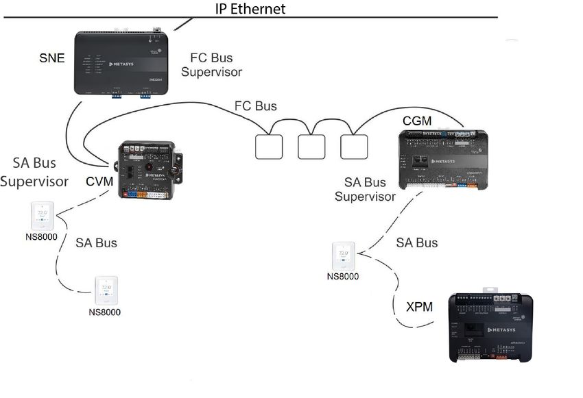
Document introduction
BACnet is a data communications protocol that supports communication and control of
applications and their associated equipment. BACnet protocol Multidrop Serial Bus/Token
Passing (MS/TP) is a peer-to-peer, multiple manager protocol based on token passing. A token is
information packets in the form of a pulse signal that is passed between devices on a network bus.
This document describes the specifications, device limits, and rules of the MS/TP communications
bus, as well as how to wire and terminate devices, and troubleshoot device communication on
the MS/TP bus. The remote MS/TP field bus is also described. With the addition of a BACnet IP to
BACnet MS/TP Router, the Remote Field Bus allows connection to remote equipment controllers
over IP.
This document is intended for the user who needs to know the rules, requirements, limits,
specifications, and configuration of the MS/TP bus to design, wire, or troubleshoot an MS/TP
application.

Summary of changes
The following information is new or revised:
  •   Updated Related documentation table to include the latest SNE and SNC engines, and the
      Open Application Server (OAS).
  •   Updated document to include the new XPM I/O expansion modules.
  •   Updated document to include the new WRG1830/ZFR183x Pro Wireless Field Bus System.
  •   Removed TEC30xx from previous references to TEC26xx and TEC30xx series thermostats.
  •   Removed the Number of NS series devices supported on the SA Bus section.
  •   Revised the SA Bus device limits section.
  •   Updated SA Buses with multiple network sensors section with NS8000 series images.
  •   Updated SA Bus rules and specifications with Table 8.
  •   Replaced the term supervisory engine with network engine throughout.
  •   Changed MS/TP to stand for Multidrop Serial Bus/Token Passing and replaced the term Master
      with Manager.

MS/TP Bus overview
The BACnet protocol MS/TP communications bus is a local network that connects supervisory
controllers and equipment controllers to field point interfaces. The bus is based on BACnet
standard protocol ANSI/ASHRAE Standard 135.
The BACnet MS/TP protocol is a peer-to-peer, multiple manager protocol based on token passing.
Only manager devices can receive the token, and only the device holding the token is allowed to
originate a message on the bus. The token is passed from manager device to manager device
using a small message. The token is passed in consecutive order starting with the lowest address.
Subordinate devices on the bus only communicate on the bus when responding to a data request
from a manager device.
      Important: Do not connect MS/TP devices and N2 devices to the same bus. MS/TP
      communications buses follow different protocol and wiring rules from N2 communications
      buses, and MS/TP devices and N2 devices are not compatible on the same bus.

MS/TP Communications Bus Technical Bulletin                                                     5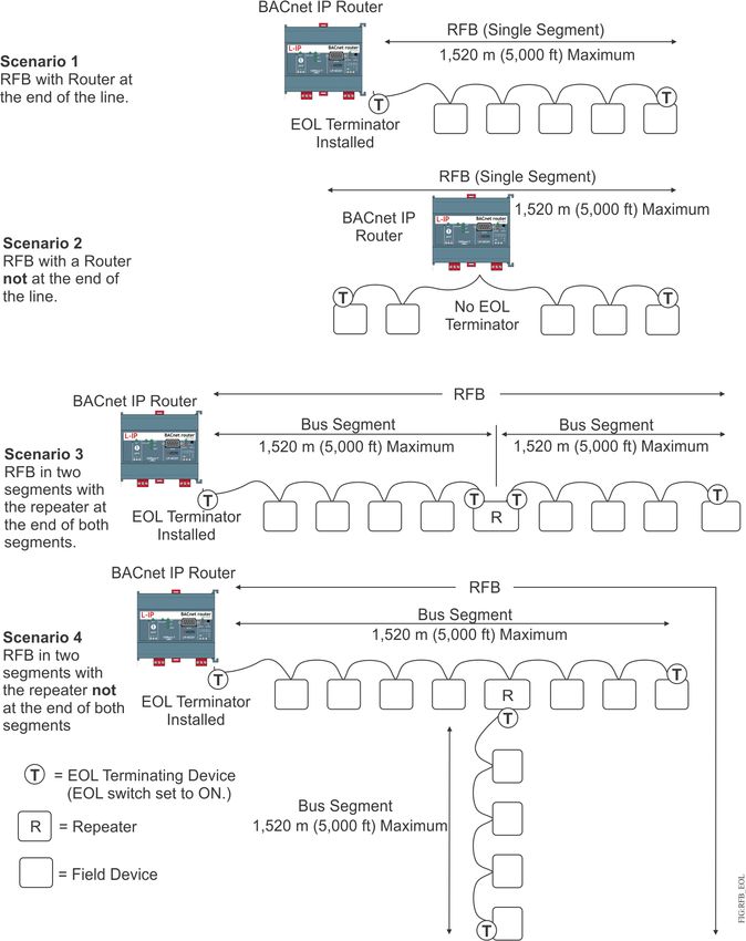
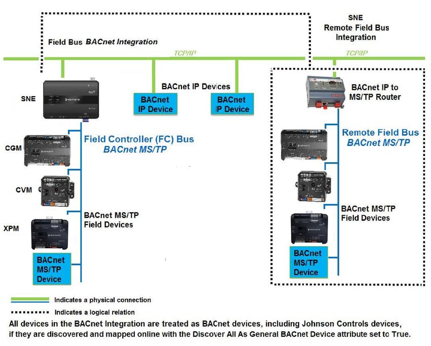
An MS/TP bus is used for two types of buses: a Field Controller bus (FC) and a Sensor Actuator (SA)
bus (Figure 1). The MS/TP bus can also be extended remotely over the IP network with the addition
of a BACnet IP to MS/TP router.
The FC bus, SA bus, and Remote Field Bus are networks of daisy-chained devices. Each bus has
only one bus supervisor, depending on which controllers are connected. On a local FC bus, the bus
supervisor is the network engine. On the local SA bus, the bus supervisor is a field controller. On
the Remote Field Bus, the bus supervisor is the BACnet IP to BACnet MS/TP Router (hereafter called
the BACnet Router), which works with the network engine when a Remote Field Bus is installed.
     Note: When you install a BACnet Router for adding a Remote Field Bus to the job site, you
     need a site-level, unique MS/TP network number and device object ID (if it contains a device
     object) for the BACnet Router. In addition, it is critical that you determine if a BACnet Broadcast
     Management Device (BBMD) is required for the BACnet Router. If you configure the BACnet
     Router as a BBMD, assign a static IP address to both the router and the NxE or ODS where you
     are configuring the MS/TP bus. For an existing installation, contact the BAS Manager, Building
     Manager, or IT department for information on available network numbers, device object IDs,
     and existing BBMDs for crossing IP subnets. Information on configuring a BBMD in a BACnet
     Router (if it supports them internally) is available from the router vendor.
The bus supervisor communicates with devices on the supervised bus and with devices on the next
(higher level) bus on the network. The bus supervisor typically starts the communication on the
FC bus, remote FC bus, or SA bus. If an SA bus, FC bus, or Remote Field Bus does not have a bus
supervisor, the manager device with the lowest device address value on the bus and a specific baud
rate selected starts the communication.
The WRG1830/ZFR183x Series Wireless Field Bus System enables wireless communication on
an MS/TP bus, allowing you to create wireless connections between Metasys General Purpose
Application Controllers (CGMs), VAV Box Controllers (CVMs), Advanced Application Field Equipment
Controllers (FACs), Field Equipment Controllers (FECs), or VAV Modular Assemblies (VMAs), Input/
Output Modules (IOMs) Expansion Modules (XPMs), and Network Automation Engines (NAEs),
Network Control Engines (NCEs), SNCs, and SNEs.
See Enabling equipment controllers for wireless operation and Related documentation for detailed
information about the WRG1830/ZFR183x Series Wireless Field Bus System.
     Note: The ZFR1800 Series Wireless Field Bus System is not supported on the Remote Field Bus.

FC Bus
An FC bus connects a Metasys system NAE, NCE, SNC, or SNE to CGMs, CVMs, FACs, FECs, VMAs
or TEC36xxs, IOMs and XPMs. Third-party BACnet MS/TP devices such as the TEC26xx series
thermostats can also be connected to the FC bus.

 6                                                            MS/TP Communications Bus Technical Bulletin
Figure 1: Example of an MS/TP communications Bus

On an FC bus, the NAE, NCE, SNE, and SNC is the bus supervisor. An FC bus supports up to three
bus segments that are connected with network repeaters (Figure 10). See Local FC Bus rules and
specifications for more information.

SA Bus
The SA bus connects NCEs, SNCs, CGMs, CVMs, CGEs, CVEs, FACs, FECs, and VMAs (equipment
controllers) to endpoint devices, such as IOMs, XPMs, network thermostats, network sensors, and
Johnson Controls Variable Speed Drives (VSDs).
On an SA bus, an NCE, SNC, CGM, CVM, CGE, CVE, FAC, FEC, or VMA is the bus supervisor. The SA
bus is a private MS/TP bus that only supports those devices that can be defined using the Controller
Configuration Tool (CCT) programming tool. The bus does not support bus segments (Figure 14).
See SA Bus rules and specifications for more information.

Remote Field Bus
The Remote Field Bus uses a BACnet Router to connect remote BACnet MS/TP devices to the
Metasys network. These devices include CGMs, CVMs, CGEs, CVEs, FACs, FECs, VMAs, IOMs, and
XPM expansion modules, ZFR Pro Wireless Gateways (WNC and WRG), the VRF Smart Gateway
and Lutron Gateway, TEC36xx Series thermostats, and other BACnet MS/TP field devices. Although
several routers from different manufacturers are available, the recommended device is the LIP-
ME201 BACnet Router from Loytec™ Electronics GmbH. Do not use any USB-powered MS/TP to IP
converter, including the Johnson Controls® BACnet to MS/TP Router (TL-BRTRP-0).
Use a Remote Field Bus for applications where connecting an RS-485 network directly to a network
engine is not practical because of distance, cost, or poor accessibility. In many cases, an IP network
connection is available at both the network engine and at some point near the BACnet MS/TP

MS/TP Communications Bus Technical Bulletin                                                         7
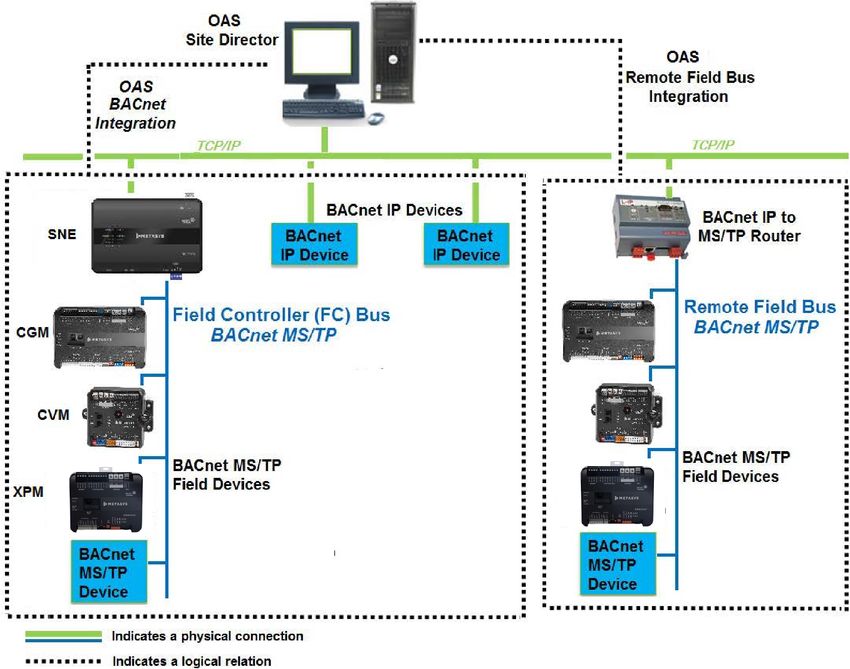
devices. By leveraging the Metasys Remote Field Bus capability with installing the BACnet Router
near the BACnet MS/TP devices, you can reduce system cost. Also, when you choose MS/TP device
integration with a router rather than BACnet Integration, access to proprietary attributes, message
types, and objects from Metasys equipment controllers is available. This functionality provides
you with more information and more capability than the standard BACnet attributes, services,
and object types. For example, at the Site Management Portal you can view proprietary attributes
such as communication statistics from mapped Metasys equipment controllers. Also, remote
MS/TP device integration supports the CCT Passthrough option for downloading devices directly
connected to the Remote Field Bus (but not to devices connected to the sensor bus).
Figure 2 shows an example of a Metasys network with a Remote Field Bus.

Figure 2: Example of a Remote Field Bus

The Remote Field Bus is defined at a Metasys network engine or OAS Workstation (Figure 3)
through field bus integration, similar to how a local MS/TP field bus is added. The Remote Field Bus
appears on the All Items Navigation tree in the Site Management Portal UI. You can also provide a
custom name to clearly identify the type of integration.

 8                                                          MS/TP Communications Bus Technical Bulletin

Note: To ensure acceptable system performance, make sure that you map all devices and
      objects that originate from a Remote Field Bus to a single network engine, for example, if you
      have two SNEs (SNE-1 and SNE-2), each with a separate Remote Field Bus. Device 1 is defined
      under SNE-1, and Device 2 is defined under SNE-2. In this arrangement, make sure you do
      not map Device 1 to SNE-2 or map Device 2 to SNE-1. If you mix remote field device mapping
      between supervisory engines, the Metasys system may start very slowly, and devices may have
      difficulty staying online.

Figure 3: Example of a Remote Field Bus with OAS

Applications for the Remote Field Bus include:
  •   Any intra-building, inter-building, or remote location that has IP network connections readily
      available
  •   Locations where it is cost prohibitive or difficult to run MS/TP wiring between devices and the
      supervisory engine, due to distance, cost, accessibility, or customer factors
  •   Locations where equipment controllers are segregated from the network engine
  •   Intra-building applications that connect segregated locations within a building (for example,
      connecting penthouses to mechanical rooms)
  •   Remote buildings where an MS/TP bus is not already available, but an Ethernet BACnet/IP
      network is (for example, university or hospital campuses)

MS/TP Communications Bus Technical Bulletin                                                           9
• Sites with a reliable network between buildings that do not need to have a separate SNE or
NAE for the building (for example, school districts)
Note: The ZFR1800 Series Wireless Field Bus System is not supported on the Remote Field Bus.
For details on how to add a Remote Field bus, refer to the MS/TP Field Bus Integration Object section
in Metasys SMP Help (LIT-1201793). For details about how to add a Remote Field Bus to a Metasys
network engine with an ODS, refer to the ODS Commissioning Guide (LIT-12011944). For details on
the VRF Gateway, refer to the VRF Smart Gateway User's Guide (LIT-12012385).
Additional background on the Remote Field Bus is covered in the following sections:
• BACnet router configuration
• Network engine configuration for adding Remote Field Bus
• BACnet Router Wiring
• Remote Field Bus restrictions
• Remote Field Bus status and statistics attributes
• Remote Field Bus status commands
BACnet router configuration
Configuration of the BACnet Router varies by vendor and model of the device, but several
important configuration settings are required for all routers. Table 1 lists those settings and Figure
4 provides an example. For more details on BACnet Router parameters, refer to the documentation
provided with your router.
Note: When you install a BACnet Router for adding a Remote Field Bus to the job site, you
need a site-level, unique MS/TP network number and device object ID (if it contains a device
object) for the BACnet Router. In addition, it is critical that you determine if a BACnet Broadcast
Management Device (BBMD) is required for the BACnet Router. If you configure the BACnet
Router as a BBMD, assign a static IP address to both the router and the SNE or NxE or ODS
where you are configuring the MS/TP bus. For an existing installation, contact the BAS
Manager, Building Manager, or IT department for information on available network numbers,
device object IDs, and existing BBMDs for crossing IP subnets. Information on configuring a
BBMD in a BACnet Router (if it supports them internally) is available from the router vendor.
10 MS/TP Communications Bus Technical BulletinTable 1: BACnet router attributes
BACnet router attribute Description User action or Recommended Setting
name
Network number (for A unique identifier defined for the BACnet Specify the network number assigned for BACnet/
ethernet BACnet/IP) IP network connection on the BACnet IP connections to the BACnet network. Do not
Router. The network engine uses this use 2000 or 65000 as the network number; these
number to locate the device. numbers are used for existing embedded networks.
Note: In most cases, the IP side of the BACnet
Router shares the same Network Number as
all of the BACnet IP connections in one BACnet
network (example: 1001). Figure 4 shows an
example.
Network number (for A unique identifier defined for the BACnet Specify the network number for the BACnet Router
BACnet MS/TP, Port 1) MS/TP network connection on the BACnet on the MS/TP side with the network address
Router. specified in the Metasys network engine under
which the Remote Field Bus is defined. The MS/TP
side of each BACnet Router must have a unique
Network Number for the site because each remote
bus is a separate network (example: 2801, 2802,
2803). Do not use the same network number as any
of the SNE or NAE MS/TP trunks. Figure 4 shows an
example.
Device ID The Device ID is the instance number for Specify a unique number.
the BACnet Router. This number must be Note: As you add routers, be sure to replace
unique across the building networks for all the router's default device ID with a unique
device instances. value for your site. The router's device ID
must be different from the device ID of all
other BACnet devices at the site.
Device name A name to identify the BACnet Router. This Specify a unique name.
name must be unique across the building
network.
BACnet/IP Broadcast The IP network subnets used by both the Enable and configure the router BBMDs with an
Management Device BACnet Router and the network engine appropriate broadcast distribution table.
(BBMD) normally require that you define BBMDs
on each subnet if those IP subnets are
different. Each IP subnet generally requires
exactly one defined BBMD. Many routers
include BBMD capability in order to
simplify this requirement.
MS/TP MAC address The MS/TP MAC address of the BACnet default=0
Router you select must not conflict
with any other MS/TP device on the
same wire. Address zero (0) is generally
recommended. For other field devices
connected to the same RS-485 MS/TP
bus, use sequential addressing following
the Metasys MS/TP bus addressing
recommendations and reserved addresses.
No single MS/TP MAC address can be used
by more than one device on the same MS/
TP bus regardless of the type of device.
Baud rate The RS-485 connection on the BACnet 38400
Router requires a specified baud rate
in order to initiate communication with
field devices that may use auto-baud rate
configuration.
MS/TP Max Manager The highest manager MS/TP node number 127
used on the bus.
MS/TP Communications Bus Technical Bulletin 11Table 1: BACnet router attributes
BACnet router attribute Description User action or Recommended Setting
name
MS/TP Max Info Frames The Max Info Frames setting on the BACnet 80 to 100 (all devices are Johnson Controls field
Router you specify should be high enough devices)
to allow the transmission of at least as or
many MS/TP frame packets as there are 20 (some or all devices are third-party field devices)
available MS/TP frame buffers in the
router.
Max APDU Length The maximum size of a BACnet APDU 480
(Application Layer Protocol Data Unit) (or use default)
accepted by the device. For most BACnet
Routers, this is a read-only attribute that
is fixed to the maximum value defined for
BACnet MS/TP.
Router configuration A password that you must enter to access To protect from intruders, change the default
password (if available) the BACnet Router configuration settings. password.
IP settings The BACnet Router requires common IP Set these appropriately for the site and the router.
communication configuration settings for
the UDP port (default 47808), IP network,
and IP subnet mask.
12 MS/TP Communications Bus Technical BulletinFigure 4: Setting network address or network number For BACnet/IP configuration you need to match the network number specified on the IP side of the BACnet Router with the network address specified in the device object of the engine of the OAS. See Figure 4. For BACnet MS/TP configuration match the network number specified on the MS/TP side of the BACnet Router with the network address specified under the Hardware tab of the Remote Field Bus Integration. The network address must be unique for each remote field bus at the site. See Figure 4. Network engine configuration for adding Remote Field Bus You define the Remote Field Bus at a Metasys network engine much like you define a local field bus. Important settings include Trunk Number and Network Address. Trunk number On a network engine, trunk numbers 1 and 2 are reserved for the local field bus integration. Trunk numbers 3 to 20 are reserved for Remote Field Bus integrations. The quantity of field buses supported on any particular device varies according to the specific device in use. Generally, the MS/TP Communications Bus Technical Bulletin 13
number of supported trunks is less than the maximum trunk number allowed (Table 2). For
example, an OAS supports 16 field buses maximum, not 20 field buses as the trunk number range
would suggest. If the specific device does not support a local field bus, start with trunk 3, as trunk
numbers 1 and 2 are not supported.

Network address
The network address you specify for a Remote Field Bus integration must match the BACnet Router
MS/TP-side network number you specify. The network address must be unique at the site. Keep in
mind that each MS/TP trunk on each SNE has a network number that needs to be considered when
determining a unique ID. This address is used to locate and establish communication between the
Remote Field Bus and the router. A defined Remote Field Bus can only work with one router. If you
need to change the network address of a Remote Field Bus after it has been configured, you must
restart the Metasys network engine to complete the re-configuration.

Number of Field Buses allowed
The total number of local and remote field buses allowed depends on the type of controller as
outlined in Table 2. For example, an NIE55 can have up to eight field buses, but an NCE25 or NIE29
can only support one local field bus and no remote field bus.

Table 2: Maximum number of Field Buses per controller
Controller                                           Maximum number of Field Buses (local and remote)
OAS                                                  18 remote field bus only
SNE2200x-0                                           8
SNE110Lx-0                                           1
SNE1050x-0 / SNE1100x-0                              4
SNC2515x-0x                                          3 remote field bus and 1 local field bus
SNC1612x-0x                                          3 remote field bus and 1 local field bus
NAE85 / NIE89                                        16
NAE55 / NIE59                                        8
NAE35 / NAE45 / NIE39 / NIE49                        4
NCE25 / NIE29                                        1 (local field bus only; remote field bus not supported)
ODS                                                  16

     Note: The SNC requires Release 11.0 or higher to support the Remote Field Bus integration.
     Note: The Remote Field Bus supports up to 32 field devices per BACnet Router on a bus
     with all Johnson Controls devices, or up to 16 field devices on a bus with a mix of Johnson
     Controls and third-party devices. Limitations are listed in the Metasys System Configuration
     Guide (LIT-12011832). Also, to take advantage of bus diagnostics, at least one Johnson Controls
     field device is required on the Remote Field Bus.
Configuration attributes only for Local Field Bus
If the same field bus configuration attribute is specified at both the BACnet Router and the Remote
Field Bus, the attribute setting on the BACnet Router prevails. For example, if a Baud Rate of 38400
is specified at the BACnet Router but a Baud Rate of 76800 is specified on the Remote Field Bus,
38400 is used as the Baud Rate on the bus. To be consistent, we recommend that you match the
Remote Field Bus attribute values with that of the router, or you can keep the default values at the
Metasys network engine. See BACnet router configuration for a partial attribute list.

14                                                              MS/TP Communications Bus Technical Bulletin
BACnet Router Wiring
Figure 5 shows how to wire the BACnet Router to the Metasys system. This example features the
Loytec Router, Model LIP-ME201C, the recommended device from Loytec Electronics GmbH.
Figure 5: Wiring BACnet Router
Note: Configure the BACnet Router before you connect it to the building network. If the
BACnet Router is commissioned using the IP, use an Ethernet patch cable. Terminal 1 on the
router is for the reference wire. Not all devices use the same markings.
Remote Field Bus restrictions
Compared to the local MS/TP field bus, the Remote Field Bus has several operational restrictions.
Number of equipment controllers on a Remote Field Bus
The number of controllers that can successfully operate on a Remote Field Bus is generally less
than that of a local field bus, and is heavily dependent on the capabilities of the router used.
Generally, a good quality router can support at least 10 BACnet MS/TP devices, and some can
support more (see Table 10). If you notice that devices go offline randomly, or you notice a large
MS/TP Communications Bus Technical Bulletin 15number of BACnet message retries, you may have exceeded the maximum number of supported
devices for the router. You may be able to use a larger number of devices if you mitigate the
message traffic that originates from field devices located on the Remote Field Bus.
Note: While the router may support at least 10 BACnet MS/TP devices, broadcast messages
are put on the MS/TP bus through the router site so the controllers may not be able to handle
the broadcast receive rate.
Maximum Change of Values (COVs)
The total number of COVs per network engine must remain at less than 500 per minute. To
determine and tune the number of COVs per minute on a Remote Field Bus, use the FDD tool, but
only if you have at least one Johnson Controls equipment controller on the bus. The FDD tool helps
you find chatty devices and helps decrease the COV rate by updating the COV increments.
Equipment controller Main Code release
For Remote Field Bus compatibility, the Main Code for the equipment controllers you connect to
remotely must be at Metasys system Release 5.3 or later. Remote field bus communication is not as
robust with controllers that are running older releases of the Metasys system.
CCT Passthrough loading
Generally, you can upload and download code and applications with CCT Passthrough for devices
directly connected to a Remote Field Bus (subject to router message load levels). However, you
cannot use CCT Passthrough to download code to an IOM connected to the SA bus of an equipment
controller. In these situations, use a Wireless Commissioning Controller at the remote location.
Device and point mapping
When you define a Remote Field Bus, be sure to map all devices and points at the remote
controllers through the same Remote Field Bus. For most networks, a detrimental increase in
router traffic occurs if multiple integrations use the same router and network number. This is true
regardless of where the multiple integrations are defined or if a BACnet Integration is used.
Remote Field Bus status and statistics attributes
With the local field bus, the status and statistics values are obtained directly from the MS/TP
communication software, which has direct access to the MS/TP communication frames. However,
with the Remote Field Bus, the status and statistics values must be obtained from one of the
remote Metasys Family BACnet controllers communicating through the BACnet Router. When at
least one Metasys MS/TP equipment controller is mapped to the Remote Field Bus as a Metasys
Family BACnet device, the system can retrieve and display the status and statistics values from the
Remote Field Bus. Be aware that if this equipment controller goes offline and a different Metasys
equipment controller is selected to provide remote bus statistics, the values obtained may abruptly
change because the values are from a different controller. This is normal operation.
The following Metasys attributes are located under the Diagnostics tab of a Remote Field Bus.
Logging object reference
This attribute indicates the remote Metasys MS/TP equipment controller configured for obtaining
MS/TP trunk status and statistics values. The device name appears if available; otherwise, the
MAC address on the MS/TP trunk appears. The value is empty for a local field bus, or if no Metasys
equipment controller is available or known. The remote Metasys device is chosen by first looking
for an online, mapped Metasys BACnet device. If none is found, then the Analyze Field Bus
command results (if any) are scanned for a possible Metasys family device.
Bus health index and Bus performance index
Trunk health and performance moving average calculations are generally delayed one update
time (usually one minute) on a Remote Field Bus due to the delays in reading raw statistics values
16 MS/TP Communications Bus Technical Bulletinremotely. As mentioned previously, the numbers reported experience a transient glitch if you
change the Metasys BACnet device used to gather statistics.
Port status
The value of this attribute is Remote Trunk for a Remote Field Bus. For an online local field bus, the
value of this attribute is Active.
Remote Field Bus status commands
The Site Management Portal UI offers a few commands that relate to Remote Field Bus operation.
Latch Statistics
The Latch Statistics command is redirected to the Metasys BACnet Device used for collecting MS/TP
trunk statistics.
Clear Statistics
The Clear Statistics command is redirected to the Metasys BACnet Device used for collecting MS/TP
trunk statistics. If the device used for collecting statistics changes after this command is issued, the
new device is not cleared unless the command is issued again.
Sync Field Device Time(s)
The Sync Field Device Time(s) command sends a high-priority time synchronization command to
all child BACnet Integration devices, based on each device mapper object's Manual Time Sync Type
attribute.
If the Manual Time Sync Type is set to:
• UTC: UTC time synchronization message is sent.
• Local: A local time synchronization message is sent.
• None: No message is sent.
• Auto: The mapper object's Protocol Services Supported attribute is used to determine which
type of time sync is supported, and if:
- utcTimeSynchronization is set, the code functions as if Time Sync Type is set to UTC.
- utcTimeSynchronization is not set and timeSynchronization is set, local time is set.
- neither utcTimeSynchronization nor timeSynchronization is set, an error is returned.
Analyze Field Bus
The Analyze Field Bus option has been modified on a Remote Field Bus to use BACnet services that
can pass through routers. (The local field bus operation can use MS/TP test messages, which do
not pass through routers.) In addition, the bus can only detect remote devices that answer the wild
card device instance value of 4194303. Some commonly used MS/TP devices do not respond to the
wild card device instance value and are not detected by this operation. Devices already mapped are
always displayed.
Note: Running a bus analysis remotely requires significantly more time to complete than what
a local field bus requires, and adds significant message loading to the router while running.
End-of-line termination on the MS/TP Bus
Daisy-chained RS485-protocol networks typically require some type of end-of-line (EOL) termination
to reduce interference caused by signal reflection that occurs when data transmissions reach
the end of a bus segment and bounce back on the segment. The high baud rates on MS/TP bus
applications require robust EOL termination and strict adherence to the EOL termination rules.
Figure 6 shows an example of the EOL termination settings on an MS/TP bus application.
MS/TP Communications Bus Technical Bulletin 17The EOL termination requirements for the FC bus are different from the SA bus requirements.
See End-of-line termination on local FC Bus and End-of-Line termination on SA Bus for more
information.
Also, third-party MS/TP devices, such as TEC26xx Series thermostats, have different EOL termination
requirements from Metasys devices on the FC bus. See TEC26xx series thermostats and third-party
MS/TP devices for more information.
Figure 6: EOL terminations on an MS/TP Bus
Baud rates on the MS/TP Bus
An MS/TP bus can be configured to communicate at one of four different baud rates. All of the
devices on an MS/TP bus must communicate at the same baud rate.
The baud rate setting determines the rate at which devices communicate data over the bus. The
baud rate settings available on Metasys MS/TP devices are 9600 bps, 19.2 kbps, 38.4 kbps, 76.8
kbps, and Auto. The baud rate setting for Metasys devices is set in the Metasys software.
Note: The BACnet Standard only requires support for 9600 and 38400 baud. Some third-
party vendor devices might not support all the baud rates supported by the Metasys system.
Reducing the baud rate to accommodate these devices affects overall performance.
18 MS/TP Communications Bus Technical BulletinWe recommend setting all MS/TP bus supervisors to 38,400.
We recommend setting all equipment controllers on the FC bus or Remote Field Bus (CGMs, CVMs,
FACs, FECs, VMAs, XPMs, and IOMs) to Auto. In the Auto setting, the Metasys devices listen for the
bus supervisor to communicate first; the devices then automatically set their baud rate to the bus
supervisor’s baud rate. CGMs, CVMs, FACs, FECs, VMAs, XPMs, and IOMs ship with a default baud
rate setting of Auto.
If you anticipate critical peer-to-peer communication and therefore do not want equipment
controllers to wait for the bus supervisor to establish the baud rate, you can specify the baud rate
for each device immediately at startup. Choose the baud rate carefully if you use this method, since
changing it requires changing each device separately.
Typically, the baud rate setting on bus repeaters and third-party MS/TP devices is configured
manually at the device, and the baud rate setting must match the bus supervisor’s baud rate.
A third-party device that does not support auto-baud establishes the baud rate for the MS/TP
network if the NxE or SNE is not connected. Refer to the manufacturer’s product documentation for
information on setting the device’s baud rate.
The Metasys software contains the following two device attributes that relate to the baud rate:
• Baud rate selection allows you to set the baud rate for the device using the System
Configuration Tool (SCT) for SNE or NAEs, or the CCT for CGMs, CVMs, FACs, FECs, VMAs, XPMs,
and IOMs.
• Active baud rate allows you to view the baud rate at which the device is communicating on
the active bus when Auto baud is selected for the device.
For more information on Metasys system attributes, refer to the Metasys system Help (LIT-1201793).
The high baud rates capable on MS/TP buses limit the range of wire gauges used on the bus. The
baud rate, wire gauge, wire length, and the number of devices are related. Higher baud rates
support more devices but require small gauge wire that provides lower capacitance. A lower baud
rate may be required to use existing, larger gauge wire that has higher capacitance, but may
support fewer devices. We recommend 38,400 baud using 22 AWG stranded wire. This combination
provides the best balance between performance and installation sensitivity.
For information on determining wire gauges, wire lengths, and the number of devices supported,
see MS/TP Bus cable recommendations.
Device addressing on the MS/TP Bus
Each device connection on an MS/TP bus requires a device address to coordinate communication.
Each bus has a set of device addresses that is separate and independent from the device addresses
on all other buses. Devices connected to both an MS/TP bus and SA bus have two device addresses,
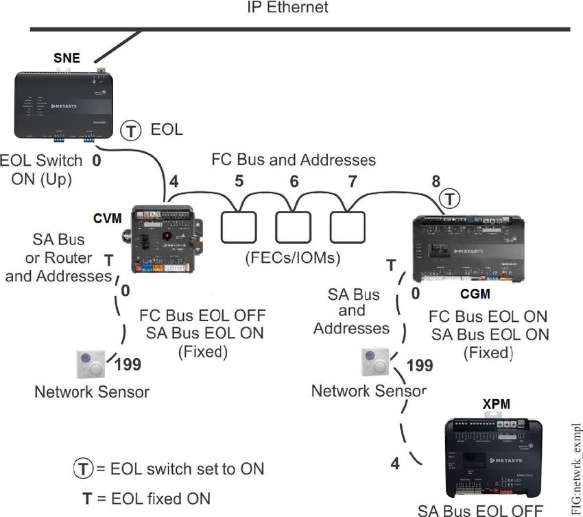
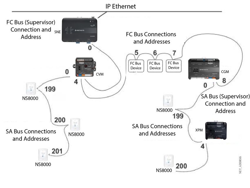
one for each bus connection (Figure 7).
In the MS/TP bus hierarchy, device connections on separate buses can have the same device
address. For example, every bus supervisor connection on an MS/TP bus has a device address of
0 (zero), and the device address for the first network sensor on any SA bus is 199. This is possible
because separate buses are identified with different network numbers. Figure 7 shows a simple
example of an MS/TP bus and the device addresses for connections on the FC bus and SA bus.
An NAE, NCE, SNE, SNC or BACnet Router is the bus supervisor on an FC bus (or Remote Field
Bus). The CGM, CVM, FAC, FEC, VMA, or the integral field controller on an NCE or SNC is the bus
supervisor on an SA bus. The supervisory devices have a default address of 0. Bus supervisors have
a fixed device address of 0 (zero) that cannot be changed (Figure 7). The current range of network
sensors are all addressable with the DIP switch set from 199 to 206 and the factory set at 199. Table
3 provides a list of the valid MS/TP device address values and address value ranges for MS/TP
devices.
MS/TP Communications Bus Technical Bulletin 19Each MS/TP manager controller passes the token to the controller with the next known address.
After 50 token passes, each controller searches for other controllers that might have joined the
network by attempting to send the token to the controller with the next consecutive address,
starting with one higher than its own, until one is found. While you do not need to address devices
on the trunk consecutively, you can improve performance by minimizing address skipping. To help
with address value selection, see Table 3.
Note: The devices on the bus do not need to be physically wired in sequential order.
Setting a device address
For most devices on an MS/TP bus, the (non-supervisory) device address is set by positioning the
Rotary or DIP switches on the device’s address DIP switch block. The DIP switch blocks are binary
switch blocks, with each switch representing a binary numerical value when the switch is in the ON
position. The CGM and CVM controllers have three rotary switches for setting the device address.
The device address set on the address DIP switch block or rotary switches applies to the device
connection on the bus where the device is not the bus supervisor. For example, the rotary switches
on CGMs or CVMs and the DIP switches on FACs, FECs, or VMAs (manager devices) set the device
address for the device connection to the FC bus (or Remote Field Bus). If the CGM, CVM, FAC, FEC or
VMA also supervise an SA bus, the controller's address on an SA bus is 0 by default (Figure 7).
An IOM or XPM has only one device connection, which can connect to either an FC bus or an SA bus
(but not both); therefore, the device address set on an IOM or XPM applies to the bus to which the
IOM is connected. (An IOM or XPM is never a bus supervisor.)
Figure 7: MS/TP Bus showing FC Bus and SA Bus addresses
20 MS/TP Communications Bus Technical BulletinTable 3: Valid MS/TP Bus address values and address ranges for MS/TP Bus devices
Address value/ Address Class Devices
range
0 Bus Supervisor FC Bus: NAE, NCE, SNE, or SNC
SA Bus: NCE, SNC, CGM, CVM, CGE, CVE, FAC, FEC, or VMA
Remote Field Bus: BACnet Router
C4-CGMs, C4-CVMs, CH-PCA, CH-PCG, or CH-PCV
1 Reserved for JCI use Reserved for the Field Inspection Tool (FIT)
2 Reserved for JCI use Reserved for Mobile Access Portal (MAP) and ZFR/ZFRPro
Wireless Field Bus Converter
3 Reserved for JCI use DIS1710 Local Controller Display
4–127 Manager Range FC Bus:
C4-CGMs, C4-CVMs, CH- CGMs, CVMs, FACs, FECs, VMAs, IOMs, XPMs, and TECs.
PCA, Remote Field Bus: CGMs, CVMs, FACs, FECs, VMAs, IOMs,
XPMs and TECs.
SA Bus: IOMs and XPMs
Note: On applications using an NCE, the address
value 4 is reserved for the NCE’s integral field
controller. On applications using ZFR1810 coordinators,
address values 120 to 127 are reserved for multiple
coordinators.
128–254 Subordinate Range Subordinate devices, VSDs, and NS network sensors on the SA
Bus. Not Supported on the FC bus.
198 Reserved VAV Balancing Sensor (handheld)
199 Reserved Most NS Series Network Sensor models or VAV Balancing
Sensor (wall-mounted)
200–219 Reserved NS Series Network Sensors
255 Broadcast Do not apply address 255 to any device.
Important: On FACs, FECs, VMAs, and IOMs only, the 128 DIP switch on the controller’s
device address DIP switch block is a mode switch used to enable the controller to operate in a
wireless mode using the ZFR Series Wireless Field Bus System. On any FAC, FEC, VMA, or IOM
that is hardwired to an MS/TP Bus, set the 128 DIP switch to the OFF position. Operating
any FAC, FEC, VMA, or IOM that is hardwired to an MS/TP Bus with the controller’s 128 DIP
switch set to the ON position results in communication failure on the bus.
As you set the device address on controllers with dip switch blocks, the best practice is to set the
highest switch value first, then the next highest switch value, and so on, until the total of the switch
values equal the intended device address. For example, positioning switches 16, 4, and 1 to ON sets
the device address to 21 for a device on the FC bus.
Figure 8: Setting the device address and wireless operation mode on the address DIP switch
block
MS/TP Communications Bus Technical Bulletin 21Notes:
• You must set switch 128 to OFF on all Metasys field controllers that are hardwired to an FC bus.
Set switch 128 to ON only on FACs, FECs, VMAs, and IOMs that operate on a Metasys ZFR Series
Wireless Field Bus.
• Devices may go offline momentarily when a device address is changed on an active bus. A
device reset is not required on equipment controllers or supervisory engines after changing
the MS/TP address.
Some devices, such as the TEC36xx Series thermostats and third-party MS/TP devices, use their
own configuration settings to establish the device address for their connection to the bus. Drilling
down through menus in software configures the addresses of the NS8000 graphical display model
and the TEC3000 series. Refer to the device manufacturer’s product documentation for instructions
on setting the device address. The device address values for TEC thermostats and all third-party
devices must comply with the rules and ranges described previously.
Rotary switch dials
The SNC has 3 rotary switch dials labeled Controller Number for setting the controller number,
which can be numbered from 000 to 999. The switches are shipped from the factory set to 000.
You can use them to set a decimal number from 000 to 999 as a unique identifier for each SNC.
The numbers are ordered from left to right, most significant bit (MSB) to least significant bit (LSB)
when the controller is oriented as shown in the following figure where the switches are set to 1 2 3
(controller address 123).
Figure 9: Rotary switch device addressing
22 MS/TP Communications Bus Technical BulletinEnabling equipment controllers for wireless operation The ZFR/ZFRPro Series Wireless Field Bus System enables wireless communication, allowing you to create wireless connections between NAEs, NCEs, SNEs, SNCs and CGMs, CVMs, FACs, FECs, or VMAs. On FAC, FEC, and VMA controllers, you can enable the controller to operate with a ZFR1800 Series wireless system and connect an MS/TP Bus in a wireless mode by setting the 128 DIP switch on the device address DIP switch block to ON. See Figure 8. CGMs, CVMs, the FAC3613 and the FAC2513 controllers auto-detect if the communication protocol is wired MS/TP, Zigbee Wireless, or N2 on the FC Bus. To operate with a ZFR Pro Series wireless field bus, a CGM, CVM, FAC, FEC, or VMA must be connected to a ZFR Pro Wireless Field Bus Router, and the associated NAE, NCE, SNC, or SNE must be connected to a ZFR Pro Wireless Field Bus Coordinator through a Remote Field Bus integration. Local FC Bus rules and specifications Table 4, Table 5, and Figure 10 provide rules and specifications for the local FC bus. (For the Remote Field Bus, see Table 10.) Metasys MS/TP devices generate less data traffic than third-party MS/TP devices and TEC26xx thermostats. Connecting third-party devices or TEC26xx Series thermostats to the FC bus increases data traffic, reduces bus performance, and reduces the number of devices that can be connected to the FC bus. MS/TP Communications Bus Technical Bulletin 23
Table 4: Local FC Bus rules and limitations
Category                  Rules/limits
General                   NAE55 Series models can support up to two local FC buses.
                               Note: When a second FC bus is added to the NAE, be sure the trunk number has
                               not been used on the NAE and enter a Network Address that is unique for the entire
                               site. This applies for any model of NAE.

                          NAE45 Series models can support one local FC bus.
                          NAE35 Series models can support one local FC bus (but an NAE35 FC bus supports only
                          half the number of devices that are supported on an FC bus on an NAE45 or NAE55).
                          NCE25 Series models can support one local FC bus. NCEs must be ordered specifically as
                          N2 or MS/TP models.
                          NAE85 / OAS / ODS do not support local FC bus. See Table 10 for the Remote Field Bus
                          specifications.
                          SNE22xxx Series models can support two local FC bus.
                          SNE11xxx Series models can support one local FC bus.
                          SNE105xx Series models can support one local FC bus.
                          SNC2515x-0x Series models can support one local FC bus.
                          SNC1612x-0x Series models can support one local FC bus.
                               Note: BACnet MS/TP only supports the daisy chain configuration.

                               Refer to the Network Engines Product Bulletin (LIT-12012138) and the
                               Network Controller Engine Product Bulletin for complete information
                               on MS/TP bus support on NAE/NCE/SNC/SNE models.

24                                                                MS/TP Communications Bus Technical Bulletin
Table 4: Local FC Bus rules and limitations
Category Rules/limits
Number of devices and Bus NCE25 models support 32 MS/TP devices (maximum) on an FC bus trunk and up to 3 bus
segments segments.
NAE35 models support the following device limits on an FC bus trunk:
When all of the devices connected on the FC bus are Metasys devices or non-Metasys
devices such as the PK-OEM, ATC, VAC, VEC, and ZEC, the device and bus segment limits
are as follows:
• 50 devices total per FC bus (maximum)
• 3 bus segments per FC bus (maximum)
When one or more non-FEC family device is connected on the FC bus, the device and bus
segment limits are as follows:
• 32 devices total per FC bus (maximum)
• 3 bus segments per FC bus (maximum)
NAE45 and NAE55 models support the following device limits on an FC bus trunk:
When all of the devices connected on the FC bus are Metasys devices or non-Metasys
devices such as PK-OEM, ATC, VAC, VEC, and ZEC, the device and bus segment limits are as
follows:
• 100 devices total per FC bus (maximum)
• 3 bus segments per FC bus (maximum)
• 50 devices per bus segment (maximum, not to exceed 100 devices per FC bus)
When one or more non-FEC family device is connected on the FC bus, the device and bus
segment limits are as follows:
• 64 devices total per FC bus (maximum)
• 3 bus segments per FC bus (maximum)
• 32 devices per bus segment (maximum, not to exceed 64 devices per FC bus)
When one or more non-FEC family device is connected on the FC bus, the device and bus
segment limits are as follows:
SNE22xxx models support the following device limits on an FC bus trunk: 64
SNE11xxx models support the following device limits on an FC bus trunk: 64
SNE105xx models support the following device limits on an FC bus trunk: 32
SNC2515x-0x models support the following device limits on an FC bus trunk: 32
SNC1612x-0x models support the following device limits on an FC bus trunk: 32
Bus segments on an FC bus are connected with repeaters (only). Up to two cascaded
repeaters may be applied to an FC bus (to connect three bus segments).
Cable length for FC Bus and When all of the devices connected on the FC bus are Metasys devices the cable length
Bus segments limits (using 22 AWG 3-wire twisted, shielded cable) are as follows:
• Each bus segment can be up to 1,520 m (5,000 ft) in length.
• Each FC bus can be up to 4,570 m (15,000 ft) in length.
When one or more non-FEC family or third-party MS/TP device is connected on the FC bus,
the device and bus segment limits are as follows:
• Each bus segment can be up to 1,220 m (4,000 ft) in length.
• Each FC bus can be up to 3,660 m (12,000 ft) in length.
Note: Do not place subordinate devices on the FC bus. Subordinate devices on the
FC bus are not supported.
When using fiber-optic connections: 2,010 m (6,600 ft) between two fiber modems.
Recommended cable 22 AWG Stranded, 3-Wire Twisted, Shielded Cable
EOL termination The EOL switch must be set to On (or an EOL terminator installed) on the two devices
located at either end of each bus segment on an FC bus. The EOL switches must be set to
Off (or EOL termination disabled) for all other devices on the bus segment on an FC bus.
See End-of-line termination on local FC Bus for more information.
MS/TP Communications Bus Technical Bulletin 25Notes:
• The recommended cable type provides the best bus performance. See MS/TP Bus cable
recommendations for information on alternative cable types and lengths that may be used in
MS/TP applications.
• If third-party devices are connected to the bus, the cable lengths should be reduced (if
necessary) to match the third-party vendor recommendations.
Figure 10: FC Bus with three Bus segments connected with repeaters
Note: When third party MS/TP devices are connected to an FC Bus, a bus segment supports
only up to 32 devices and the FC Bus supports only up to 64 devices.
Note: For optimum noise protection the location with G are the ideal shield grounding
locations. This provides one shield ground per bus segment, grounding at the source of
the bus for that segment. It is also acceptable to ground the shield only at the SNE if the
shields are made continuous across repeaters side A and B; however; the noise protection is
somewhat less with the wiring configuration.
Note: While each bus segment can support up to 50 Metasys Device connections, the total on
the FC Bus cannot exceed 100, including the SNE.
The bus segments on an FC bus are connected using repeaters (only). A repeater has two device
connections, which are independent of each other. Each device connection on the repeater is
connected to a bus segment just like any other device connection on the segment, and a repeater
device connection can be connected at the end of a bus segment or anywhere along the segment.
When a repeater device connection is at the end of a bus segment, EOL termination must be
enabled on that repeater device connection. See Figure 11 for more examples of repeaters on FC
buses.
Table 5: FC Bus specifications
Category Specification
Error checking Message Headers checked using 8-bit Cyclic Redundancy Check (CRC) test.
Message data check using 16-bit CRC test.
Device addressing 0–255 (See Device addressing on the MS/TP Bus for more information.)
Data transmission standard RS485
Signaling method BACnet® MS/TP
Signaling rate 9600; 19,200; 38,400; or 76,800 baud as selected by bus supervisor. (See Baud rates
on the MS/TP Bus.)
Transient immunity Meets EN61000-4-4 and EN6100-4-5 requirements for heavy industrial applications.
Protected against misapplication of 24 VAC.
26 MS/TP Communications Bus Technical BulletinYou can also read