Mars Science Helicopter Conceptual Design - CORE
←
→
Page content transcription
If your browser does not render page correctly, please read the page content below

https://ntrs.nasa.gov/search.jsp?R=20200002139 2020-05-24T04:36:31+00:00Z

 NASA/TM—2020–220485

Mars Science Helicopter Conceptual Design
Wayne Johnson, Shannah Withrow-Maser, Larry Young, Carlos Malpica, Witold J.F. Koning, Winnie
Kuang, Mireille Fehler, Allysa Tuano, Athena Chan
Ames Research Center, Moffett Field, California

Anubhav Datta, Cheng Chi, Ravi Lumba, Daniel Escobar
University of Maryland

J. Balaram, Theodore Tzanetos, Håvard Fjær Grip
Jet Propulsion Laboratory, California Institute of Technology

March 2020
NASA STI Program ... in Profile

Since its founding, NASA has been dedicated to the • CONFERENCE PUBLICATION. Collected
advancement of aeronautics and space science. The papers from scientific and technical
NASA scientific and technical information (STI) conferences, symposia, seminars, or other
program plays a key part in helping NASA maintain this meetings sponsored or co-sponsored by NASA.
important role.
The NASA STI program operates under the auspices of • SPECIAL PUBLICATION. Scientific,
the Agency Chief Information Officer. It collects, technical, or historical information from NASA
organizes, provides for archiving, and disseminates programs, projects, and missions, often
NASA’s STI. The NASA STI program provides access concerned with subjects having substantial
to the NTRS Registered and its public interface, the public interest.
NASA Technical Reports Server, thus providing one of
the largest collections of aeronautical and space science
 • TECHNICAL TRANSLATION. English-
STI in the world. Results are published in both non-
 language translations of foreign scientific and
NASA channels and by NASA in the NASA STI Report
 technical material pertinent to NASA’s mission.
Series, which includes the following report types:

 Specialized services also include organizing and
• TECHNICAL PUBLICATION. Reports of publishing research results, distributing specialized
 completed research or a major significant phase of research announcements and feeds, providing
 research that present the results of NASA information desk and personal search support, and
 Programs and include extensive data or theoretical enabling data exchange services.
 analysis. Includes compilations of significant
 scientific and technical data and information
 deemed to be of continuing reference value. For more information about the NASA STI program,
 NASA counter-part of peer-reviewed formal see the following:
 professional papers but has less stringent
 • Access the NASA STI program home page at
 limitations on manuscript length and extent of
 http://www.sti.nasa.gov
 graphic presentations.
 • E-mail your question to help@sti.nasa.gov
• TECHNICAL MEMORANDUM.
 Scientific and technical findings that are • Phone the NASA STI Information Desk at
 preliminary or of specialized interest, e.g., quick 757-864-9658
 release reports, working papers, and
 bibliographies that contain minimal annotation. • Write to:
 Does not contain extensive analysis. NASA STI Information Desk
 Mail Stop 148
 NASA Langley Research Center
• CONTRACTOR REPORT. Scientific and
 Hampton, VA 23681-2199
 technical findings by NASA-sponsored
 contractors and grantees.

NASA/TM—2020–220485

Mars Science Helicopter Conceptual Design
Wayne Johnson, Shannah Withrow-Maser, Larry Young, Carlos Malpica, Witold J.F. Koning, Winnie
Kuang, Mireille Fehler, Allysa Tuano, Athena Chan
Ames Research Center, Moffett Field, California

Anubhav Datta, Cheng Chi, Ravi Lumba, Daniel Escobar
University of Maryland

J. Balaram, Theodore Tzanetos, Håvard Fjær Grip
Jet Propulsion Laboratory, California Institute of Technology

National Aeronautics and
Space Administration

Ames Research Center
Moffett Field, CA 94035-1000

March 2020
This report is available in electronic form at
 http://ntrs.nasa.gov

Abstract
 Robotic planetary aerial vehicles increase the range of terrain that can be examined, compared to
traditional landers and rovers, and have more near-surface capability than orbiters. Aerial mobility is a
promising possibility for planetary exploration as it reduces the challenges that difficult obstacles pose to
ground vehicles. The first use of a rotorcraft for a planetary mission will be in 2021, when the Mars
Helicopter technology demonstrator will be deployed from the Mars 2020 rover. The Jet Propulsion
Laboratory and NASA Ames Research Center are exploring possibilities for a Mars Science Helicopter, a
second-generation Mars rotorcraft with the capability of conducting science investigations independently
of a lander or rover (although this type of vehicle could also be used assist rovers or landers in future
missions). This report describes the conceptual design of Mars Science Helicopters. The design process
began with coaxial-helicopter and hexacopter configurations, with a payload in the range of two to three kg
and an overall vehicle mass of approximately twenty kg. Initial estimates of weight and performance were
based on the capabilities of the Mars Helicopter. Rotorcraft designs for Mars are constrained by the
dimensions of the aeroshell and lander for the trip to the planet, requiring attention to the aircraft packaging
in order to maximize the rotor dimensions and hence overall performance potential. Aerodynamic
performance optimization was conducted, particularly through airfoils designed specifically for the low
Reynolds number and high Mach number inherent to operation on Mars. Rotor structural designs were
developed that met blade frequency and weight targets, subject to material stress limits. The final designs
show a substantial capability for science operations on Mars: a 31 kg hexacopter that fits within a 2.5 m
diameter aeroshell could carry a 5 kg payload for 10 min of hover time or over a range of 5 km.

 Introduction
 The Mars Helicopter, launching as a part of the Mars 2020 mission, will begin a new era of planetary
exploration. Mars research has historically been conducted through landers, rovers, and satellites. As both
government and private industries prepare for human exploration of the Martian surface within two decades,
more in-depth knowledge of what awaits on the surface is critical. Planetary aerial vehicles increase the
range of terrain that can be examined, compared to traditional landers and rovers, and have more near-
surface capability than orbiters. The Jet Propulsion Laboratory (JPL) and NASA Ames Research Center
are exploring possibilities for a Mars Science Helicopter (Ref. 1), a second-generation Mars rotorcraft with
the capability of conducting science investigations independently of a lander or rover (although this type of
vehicle could also be used assist rovers or landers in future missions). JPL is leading this exploration, with
NASA Ames responsible for the aircraft sizing and packaging, rotor design, and mission performance
analysis. The University of Maryland contributed the rotor structural design and analysis. The results will
also provide baseline designs for future helicopters on Mars.
 The first use of a rotorcraft for a planetary mission will be in 2021, when the Mars Helicopter (MH)
technology demonstrator will be carried by and deployed from the Mars 2020 rover (Ref. 2). The goal of
the MH (Figure 1) is to demonstrate the viability and potential of heavier-than-air flying vehicles in the
Martian atmosphere. MH is a coaxial helicopter with a mass of 1.8 kg and rotor diameter of 1.21 m. The
helicopter relies on solar cells and a battery system for power, allowing up to 90 second flight endurance
that is conducted fully autonomously due to the communication delay between Earth and Mars. The MH
will perform five ninety-second flights as a technology demonstration of the first powered flight on another
planet.
 The Mars Science Helicopter (MSH) investigation has the goal of establishing the feasibility of flying
a larger, more capable rotorcraft on Mars. The MH does not have a dedicated science payload apart from
the instruments required for flight, and MH flights will take place over relatively flat, rock-free terrain using
a visual-inertial navigation system. The larger MSH will be capable of more payload, longer sorties, all
terrain overflight, and communication through an orbiter to enable operation at unrestricted distances from
 1

other landed assets. Initial design requirements for the MSH mission include a two to three kilogram
payload (such as could be used for onboard science instruments intended for mapping, stratigraphy, remote
sensing, etc.), an extended range (2–4 km) and increased hover time (2–4 minutes) sufficient to enable
significant science investigations both inflight as well as when on the surface. The aircraft design target
mass to accomplish such science missions is around 20 kg. The MSH vehicle will require improved
handling qualities for control, more efficient rotor blade performance, and optimized lightweight structural
design in order to be successful. This report describes the conceptual design of Mars Science Helicopters.
The goal of the vehicle design work is to establish the general capability of helicopters for science
operations on Mars.

 Figure 1. Mars Helicopter technology demonstrator, part of the Mars 2020 mission.

 Background
 Early work on aerial exploration of planetary bodies was performed by Young and Aiken, et al. (Refs.
3-6). In response to a 2002 American Helicopter Society student design competition (sponsored by NASA
and Sikorsky Aircraft), Martian rotorcraft designs were developed by University of Maryland (Ref. 7) and
Georgia Institute of Technology (Ref. 8). The University of Maryland aircraft, MARV, was designed for a
weight of 50 kg with a rotor diameter of 4.26 m, range of 25 km, and endurance of 39 min. GTMARS, the
Georgia Institute of Technology design, weighed 10 kg with a rotor diameter of 1.84 m and endurance of
30 min. More recent designs for Martian rotorcraft were developed by Georgia Institute of Technology
(MEUAV, Ref. 9), Delft University of Technology (VITAS, Ref. 10), and Tohoku University (JMH, Ref.
11). Figure 2 illustrates these designs.

 Figure 2. Martian rotorcraft designs (left to right): MARV, GTMARS, MEUAV, VITAS, JMH.

 The development of the Mars Helicopter technology demonstrator was led by the Jet Propulsion
Laboratory. Balaram, et al. (Ref. 1) described the MH project; Grip, et al. (Refs. 12-14) described the MH
flight dynamics, control, and guidance; Pipenberg, et al. (Refs 15-16) described the rotor and aircraft design
and fabrication. Koning, et al. (Ref. 17) presented performance calculations for the MH. The Mars
Helicopter is the only aircraft constructed and tested for flight on Mars (though actual flights on Mars will
not occur until 2021), so the MH weights and performance were the foundation of conceptual design of
Mars Science Helicopters.

2

Balaram (Ref. 1) described potential Mars Science Helicopter missions. The MSH will be able to
explore extreme terrains that a rover or lander could not access. For example, it can overcome and hover
next to steep slopes, fly over rocky ground, and otherwise observe hazardous terrains that would be
inaccessible to a rover. Visible imaging from a helicopter would bridge the resolution gap between orbital
images and landed investigations. One mission concept involves landing on the flat, smooth floor of a crater
with recurring slope lineae and/or gullies on its interior walls. A remote sensing platform on the lander
could perform long-duration, multi-instrument remote observations of the surrounding walls from the crater
floor. This would be augmented by contact interrogations performed by the helicopter. Another concept
involves one or more stand-alone helicopters communicating directly with orbiters to relay data to Earth.
This larger helicopter could scout out complex terrains with many different geologic features of astro-
biologic importance. Possible scientific areas of study that would be enabled by these technical capabilities
include the following.
 Mapping/Stratigraphy: A helicopter would be able to access regional geology in three
 dimensions, making it very capable for a mapping and stratigraphy investigation. Layered
 deposits, for example, could be imaged and sampled through their depths across tens to
 hundreds of kilometers.
 Polar Science: An aerial vehicle could conduct detailed mapping of ice-rich layers exposed
 at the poles (e.g., polar troughs). These layers are thought to reflect changes in climate over
 the past few million years. Steep, cliff-like terrain along the periphery of the polar layered
 deposits is another candidate site that would benefit from exploration of a Mars helicopter.
 Recurring Slope Lineae: RSL are special regions that are difficult to explore without danger
 of contamination. However, a helicopter could fly or hover over RSL without touching
 them. Spectral properties, daily changes and the timing of appearance and fading behaviors,
 and nearby moisture and wind content could all reveal the true nature of these enigmatic
 features.
 Low-Latitude Volatiles (icy scarps): An aerial platform could conduct along-scarp
 mapping of ice-rich layers comprising an ancient ice sheet, now exposed at the surface. In
 addition to characterizing icy layers, the vehicle could also study ice sheet overburden and
 the erosional products at the base of the scarp.
 Atmospheric Science: Vertical profiles could be acquired for atmospheric species of
 interest (e.g., H2O, CO2, CH4) in the lowest region of the boundary layer, which are difficult
 to obtain from orbit. Vertical changes in wind speed could also be measured. These
 measurements are crucial for understanding interaction between the surface and the
 atmosphere.
 Subsurface Geophysics: Geophysical studies of Mars are especially timely given the new
 information the InSight mission is revealing about the interior of Mars. The subsurface
 could be explored in detail over a wide area using the capabilities of a helicopter.
By providing a new platform for regional high-resolution sensing and extreme terrain access, Mars
helicopters will enable new mission concepts responsive to the strategic themes of life (access to RSL),
geology (access to diverse sites and extreme terrains), climate (direct observation of low-altitude wind
fields), and preparing for human exploration (demonstrating helicopter scouting concepts).

 Rotor Aerodynamics and Performance
The fundamentals of rotor and rotorcraft performance are presented in Reference 18. Evaluating
aerodynamic performance of a rotary wing starts with the lift and drag behavior of the airfoil sections. From
lift and drag of the sections, the thrust and power of the rotor can be calculated. The lift and drag coefficients

 3

" "
are the scaled characteristics of the section: ! = /(# # ) and $ = /(# # ); where is the section
lift, the section drag, the gas density, the speed, and the section chord. The coefficients vary with
the airfoil section angle-of-attack (Figure 3). The effects of viscosity are characterized by the Reynolds
number, = / (where is the gas viscosity). The effects of compressibility are characterized by the
Mach number, = / (where is the speed of sound in the gas). Figure 3 shows the lift and drag
coefficients as a function of angle-of-attack for several Mach numbers, for an NACA 23012 airfoil at
Reynolds numbers typical of a helicopter on Earth. For low angle-of-attack, the lift is linear with and the
drag is small. At some angle of attack (here about 12 deg for = 0.4) the flow separates from the airfoil
upper surface (the airfoil stalls), which causes the lift to decrease and the drag to increase. As Mach number
increases, the lift-curve-slope increases below stall, but the maximum lift decreases. At high Mach numbers,
shocks occur on the airfoil, and the drag rises substantially. At the very small Reynolds numbers
characteristic of flight on Mars, the maximum lift is smaller than shown in Figure 3, and the drag is greatly
increased, by a factor of 4 or 5, even at low angle-of-attack. The best (highest lift-to-drag ratio) airfoils at
low Reynolds number are thin, and compressibility effects are delayed for thin sections.

 1.6 0.30
 1.4 M=0.4 M=0.4
 0.25
 1.2 M=0.7 M=0.7
 M=0.85
 drag coefficient
 0.20 M=0.85
 lift coefficient

 1.0
 0.8 0.15
 0.6
 0.10
 0.4
 0.05
 0.2
 0.0 0.00
 -2 0 2 4 6 8 10 12 14 16 -2 0 2 4 6 8 10 12 14 16
 angle of attack (deg) angle of attack (deg)

 Figure 3. Airfoil lift and drag characteristics (NACA 23012).
 Rotor hover power consists of induced power (energy lost in the wake, because the rotor generates
thrust) and profile power (energy lost to section drag forces):

 ) 1
 = 6 + % &'(
 2 8 $ +,-.

where is the rotor power, the rotor thrust, the disk area, % the total blade area, &'( the blade tip
speed, and = % / the rotor solidity. The induced power factor is the ratio of the actual induced power
to the ideal (momentum theory) power, typically about = 1.2 in hover and = 2.0 or more in edgewise
forward flight of a rotor. The mean drag coefficient, $ +,-. , characterizes the profile power, and so the
value reflects the extent of stall on the rotor blade. The mean lift coefficient of the rotor blade is proportional
to the blade loading:
 ! +,-. /
 ≅ = #
 6 % &'(
The blade loading / / of a rotor is thus limited by stall, and the maximum or design value then determines
the blade area and tip speed required. The ratio of power and thrust can be written:

 $ +,-.
 = 6 + &'(
 2 8 / /

4

from which it follows that low disk loading / (large diameter) and high airfoil ! / $ reduces the power.
The impact of low density is to increase the induced power, and to increase the profile power through the
influence of Reynolds number on the drag coefficient. The tip speed must be high to minimize the blade
area.
 The induced power depends on the structure of the rotor wake. Figure 4 illustrates the geometry of the
wake of a hovering rotor. The photographs show the rolled-up tip vortices (visualized by natural
condensation) of a single main rotor helicopter and a coaxial rotor helicopter. The mutual interference
between the upper and lower rotor wakes in the coaxial configuration reduces the hover power, but greatly
complicates the aerodynamic analysis and design of the system. The sketch shows the basic structure of the
hovering rotor wake (of a single-bladed rotor, for simplicity). A rolled-up tip vortex with strong swirl
velocities forms just behind the blade, and convects downward and inward due to the mutual interference
with tip vortices below it. When this tip vortex encounters the following blade, it is inboard of and very
close below the tip. The airloads produced by this encounter are crucial to the performance of the rotor.
After encountering this blade, the vortex is convected downward at a higher rate, proportional to the mean
induced velocity at the rotor disk. There is also a sheet of vorticity emanating from the inboard portion of
the blade, which is rapidly convected downward.

 Figure 4. Rotor wake geometry structure in hover.
 A measure of the efficiency of a hovering rotor is the figure of merit ( ), which is the ratio of the
ideal and actual hover power required:

 '$,-! B2
 = =
 ) 1
 B2 + % &'( 8 $ +,-.
The figure of merit roughly represents the ratio of profile power and induced power, so is best used in
comparisons at fixed disk loading. Figure 5 illustrates the variation of figure of merit with rotor thrust
coefficient, showing measurements and calculations for the Mars Helicopter. The figure of merit increases
with thrust, as the induced power increases, until stall causes the profile power to increase and drops.
At low Reynolds number, the airfoil drag coefficient increases, perhaps to 4 or 5 times that shown in Figure
3, thereby increasing the profile power. Consequenty, a small helicopter on Earth has a low figure of merit.
For a rotor operating on Mars, the low density means that the induced power is also high: the rotor hovering
efficiency is good (good figure of merit, Figure 5), but the power required is large.
 The maximum Mach number of the blade occurs on the advancing tip: -& = ( + &'( )/ . The
advancing tip Mach number -& is constrained by the airfoil drag divergence, hence it is a key parameter
determining forward flight efficiency of the rotor.

 5

Figure 5. Hover figure of merit of the Mars Helicopter.

 Mars Atmosphere
 The possibilities for flight on Mars are dominated by the very low density of the Martian atmosphere.
Table 1 compares the characteristics of the atmospheres on Earth and Mars. The density on Mars is
approximately 1% of that on Earth with a variation between 0.010 and 0.020 kg/m3 depending on ground
elevation, as well as yearly and daily variations. Because of the low density, the Reynolds numbers of
airfoils on rotors designed for Martian operations are in the range 10000 to 25000, which has a significant
impact on airfoil behavior. The Martian atmosphere consists primarily of carbon dioxide, the gas properties
of which lead to lower speed of sound than in the nitrogen-oxygen atmosphere of Earth, which is
exacerbated by the low temperatures.
 The low density of the atmosphere on Mars reduces the lift per blade-area that can be produced by a
rotor. The low Reynolds number reduces the maximum lift coefficient and increases the drag coefficient of
airfoils, and the optimum airfoil shape is much different than that for high Reynolds numbers. For a given
design Mach number, the lower speed of sound on Mars reduces the maximum possible tip speed of the
rotor.

 Table 1. Comparison of atmospheres on Earth and on Mars.
 Earth (N2+O2) Mars (CO2)
 3
 Density, kg/m 1.225 0.017
 Temperature, C 15 –50
 2
 Viscosity, Ns/m 0.0000175 0.0000113
 Sound speed, m/s 340.3 233.1
 Tip speed, &'( m/s 238 163
 (Mach number = 0.7)
 Reynolds number, 1,297,000 19,100
 (Mach number = 0.5, chord = 0.1 m)

6
Computational Methods
 A spreadsheet was developed to size a helicopter for Mars missions. Calibrated to the MH, the
spreadsheet provided a simple and quick first estimate of the aircraft size. The principal software tools used
in this investigation were NDARC and CAMRAD II. The rotorcraft design and analysis code NDARC uses
detailed performance models of the rotor, battery, motor, and other components to perform more complete
analysis of missions. The rotorcraft comprehensive analysis CAMRAD II was used to calculate the
performance of the rotor and aircraft.
 NDARC (NASA Design and Analysis of Rotorcraft) is a conceptual/preliminary design and analysis
computer program for rapidly sizing and conducting performance analysis of new vehicle concepts with
particular emphasis on vertical lift configurations (Ref. 19). The design task sizes the vehicle to satisfy a
set of design conditions and missions. The analysis tasks include off-design mission analysis and flight
performance calculation for point operating conditions. The aircraft size is characterized by parameters
such as aircraft total weight, weight empty, component dimensions, battery capacity, and motor power. To
achieve flexibility in configuration modeling, NDARC constructs a vehicle from a set of components,
including fuselage, wings, tails, rotors, transmissions, and engines. For efficient program execution, each
component uses a surrogate model for performance and weight estimation. Higher fidelity component
design and analysis programs as well as databases of existing components provide the information needed
to calibrate these surrogate models, including the influence of size and technology level. The reliability of
the synthesis and evaluation results depends on the accuracy of the calibrated component models. The
NDARC rotor performance model represents the rotor power as the sum of induced, profile, and parasite
terms: = ' + 0 + ( . The parasite power (including climb/descent power for the aircraft) is obtained
from the rotor wind-axis drag force and rotor velocity. Induced power is the energy lost in the wake,
calculated from the ideal momentum theory power times an induced power factor . The profile power is
the energy required to turn the rotor in the viscous air, expressed in terms of a mean drag coefficient $ 1234 .
Performance calculations from the comprehensive analysis are correlated with test data; then rotor
performance is calculated for the full range of expected flight and operating conditions; finally, the
parameters of the NDARC rotor performance model are developed based on the calculated and $1234 .
 Performance analyses were conducted with the comprehensive rotorcraft analysis CAMRAD II (Refs.
20-22). CAMRAD II is an aeromechanics analysis of rotorcraft that incorporates multibody dynamics,
nonlinear finite elements, and rotorcraft aerodynamics. The trim task finds the equilibrium solution for a
steady state operating condition and produces the solution for performance, loads, and vibration. The
CAMRAD II aerodynamic model for the rotor blade is based on lifting-line theory, using steady two-
dimensional airfoil characteristics and a vortex wake model. The wake analysis calculates rotor nonuniform
induced velocities, using free wake geometry. Airfoil characteristics were obtained from tables for the
appropriate airfoils. Performance calculations for calibration of the NDARC rotor models considered first
an isolated rotor, in particular to define profile power including the influence of stall and compressibility.
Then calculations for the multiple rotors (coaxial or hexacopter) were used to calibrate the rotor-rotor
interference effects on induced power.
 Aircraft structural design and analysis were conducted using SolidWorks, a 3D CAD (computer aided
design) system from Dassault Systèmes. SolidWorks was also used for the packaging investigations.
 The rotor blade structural design and analysis were conducted using the three-dimensional multi-body
structural dynamics code X3D (Ref. 23), from US Army Aviation Development Directorate and the
University of Maryland. The multi-body analysis formulation of X3D models elastic components using 3D
nonlinear solid finite elements. Kinematic couplings are simulated by the multi-body analysis and 3D
stresses and strains are recovered from the finite element analysis. The FEA solver supports second order
27-node hexahedron elements. The geometry for the X3D models was constructed using CATIA, a 3D
CAD and project life cyclic management system from Dassault Systèmes. Structural analysis meshes were
defined using CUBIT, from Sandia National Laboratories.

 7
Airfoil design, analysis, and optimization were conducted using the Reynolds-averaged Navier-Stokes
computational fluid dynamics code OVERFLOW from NASA (Ref. 24). The analysis used two-
dimensional structured grids, with the implicit, compressible solver of OVERFLOW, to evaluate airfoil
section lift and drag.
 In future tasks for the Mars Science Helicopter design, flight dynamics modeling and assessment will
be performed for the rotorcraft using FlightCODE (Ref. 25).

 Helicopter Design Process
 The helicopter design process begins with the definition of the mission, particularly payload, range,
and hover time. The fundamental requirement for a reliable conceptual design of an aircraft is a complete
identification of all the components and subsystems that make up the vehicle. Then for each component,
weight and performance models are needed. The weight models reflect scaling with size of the component.
The performance models in particular are needed for rotor hover and forward flight operation. These weight
and performance models are calibrated to existing aircraft, which in the case of flight on Mars is only the
Mars Helicopter. The power system needs models for motor and battery performance. Power requirements
of the payload must also be specified.
 To start the sizing of the Mars Science Helicopter, a spreadsheet was developed, and it was calibrated
to the weight and power of the Mars Helicopter. With a preliminary examination of packaging and folding
options for a rotorcraft in an aeroshell, the spreadsheet sizing tool produced initial estimates of the designs.
Next, NDARC models were developed, with detailed performance models for the rotor, battery, and motor,
and detailed mission analysis. The weight models began in a form similar to the spreadsheet. CAMRAD II
was used to determine blade planform and twist to optimize the rotor performance, and then used to generate
rotor performance models for NDARC. The battery model was calibrated to the specification data for a Li-
ion cell. A simple motor efficiency model was used. The conceptual design process iterates between the
sizing task and the rotor performance and structural analysis.

 Mars Science Helicopter Mission
 A mission was defined by JPL for the Mars Science Helicopter. For mapping, stratigraphy, and remote
sensing operations (Ref. 1), a payload of 2.02 kg was identified. The mission consisted of the following
segments (Figure 6):
 a) 30 sec takeoff at hover power
 b) climb to altitude of 200 m
 c) 1 km cruise flight to science site
 d) 2 min hover at science site
 e) land
 f) sleep for 1 sol, and recharge
The energy source for flight is batteries, with electric motors supplying the rotor power. The aircraft does
not return to a lander (indeed, there may not be a separate lander for the mission), so the batteries are
recharged from onboard solar cells. The aircraft must have enough energy to complete the mission (with
reserves) and survive one night on the surface before recharging starts. At 30 m/sec flight speed, the mission
duration is about 3 minutes; at 4 m/sec, it is about 7 minutes. Since with electric propulsion the aircraft
weight does not change during the mission, the order of the cruise flight (1 km) and hover (2 min) operations
can be changed without affecting the design.
 The operation site chosen for design and analysis of the MSH was the Jezero Crater in the spring, for
which the typical atmospheric conditions are a density of 0.015 kg/m3 and temperature of –50 deg C.

8
Cruise
 (1 km) Hover
 Climb to (2 min)
 200m
 Land
 Takeoff
 (30 s)
 Sleep and Recharge
 Landing Site Science Site

 Figure 6. Mars Science Helicopter design mission.
 This mission was intended to be representative of a useful scientific endeavor on Mars, without being
so challenging that it was beyond projected technology. After designing a helicopter for this mission, the
possibilities for expanded capabilities were explored.

 Initial Sizing
 Two aircraft configurations were considered for the Mars Science Helicopter, illustrated in Figure 7.
The coaxial helicopter has the advantage of directly inheriting experience from the Mars Helicopter
development, testing, and operation, but has potential problems with flight dynamics (discussed below).
The hexacopter has better performance (due to lower disk loading) and flight dynamics characteristics, and
it could operate with power out to one or two rotors, but it is expected to have larger airframe weight.

 Figure 7. Mars Science Helicopter configurations, with Mars Helicopter (center) for scale.
 To start the sizing of the Mars Science Helicopter, a spreadsheet was developed, and calibrated to the
weight and power of the Mars Helicopter. The spreadsheet implemented simple models for rotor
performance, motor and battery efficiency, and component weights. The spreadsheet sizing gave an aircraft
gross weight of about 20 kg, and a rotor diameter of 2.5–2.7 m for the coaxial helicopter or 1.0–1.4 m for
the hexacopter (compared to 1.8 kg and 1.21 m for the Mars Helicopter).
 Planetary aircraft size will always be constrained by packaging for the trip to the destination. For this
initial sizing effort, the legacy Pathfinder aeroshell was considered, notably imposing a maximum diameter
of 2.5 m for the aircraft when folded/packaged in the aeroshell prior to deployment on the Martian surface.
It was assumed that the problems of landing and extraction are solvable and most of the volume within the
aeroshell is potentially usable. More detailed studies (described below) considered the volumetric
implications of not only fitting MSH vehicles inside the aeroshell but also fitting within the original
Pathfinder airbag tetrahedral petal lander.
 Numerous folding methods for both the coaxial and hexacopter designs were examined to determine
which yielded the most efficient use of the aeroshell volume. Figure 8 shows the best options for the coaxial
helicopter. The in-plane fold option permitted the largest blade radius (1.34 m), but had lower aspect-ratio
blades, since this option requires 3 blades. The droop fold option had an adequate blade radius (1.25 m),
and with 4 blades per rotor could better accommodate increased solidity. Figure 9 shows the best options
for the hexacopter. The hinged fold option had a blade radius of only 0.5 m, resulting in substantially more
weight and power for the aircraft, while the rotating arm fold option had a blade radius of 0.64 m.

 9
Figure 8. Folding options for coaxial helicopter in aeroshell.

 rotating arms hinged arms

 Figure 9. Folding options for hexacopter in aeroshell.
 The conclusion of the initial sizing and packaging effort was that there are feasible rotorcraft that can
perform the MSH design mission, although with relatively high disk loading and solidity because of the
aeroshell constraint on folded size. The aircraft considered for more detailed and accurate analysis were the
coaxial helicopter with droop fold and rotor radius of 1.25 m, and the hexacopter with rotating fold and
rotor radius of 0.64 m. The initial estimates of weight and power for these two aircraft were similar, but the
hexacopter had 57% more disk area than the coaxial helicopter, which was expected to result in a more
efficient aircraft.
 In general, using a larger aeroshell would enable a larger and more capable rotorcraft. In particular,
when the complete EDL (entry, descent, and landing) solution is considered, especially the lander, either a
less capable aircraft or a larger aeroshell may well be required.

 Rotor Performance
 The rotor performance was calculated using the lifting-line analysis of CAMRAD II, which obtains the
blade airloading and induced velocity (hence rotor power) from a distorted free wake geometry (including
interaction between the rotors, especially for the coaxial configuration) and two-dimensional airfoil tables,
which account for the effects of viscosity (drag and stall), compressibility, and Reynolds number. The
Martian operating environment is characterized by low Reynolds number, about = 11000 for MH and
 = 15000 − 25000 for MSH, and high Mach number, = 0.7 to 0.9. There is no experimental data
for airfoils at such low Reynolds number and high Mach number, so the airfoil characteristics were
calculated using OVERFLOW. These characteristics are the lift, drag, and moment coefficients as a
function of angle-of-attack and Mach numbers, for a particular atmosphere (density, speed of sound,
viscosity), chord length (so Reynolds number is proportional to Mach number), and airfoil shape.

Mars Helicopter Blade Design and Performance Correlation
 The Mars Helicopter rotor blade was designed by AeroVironment, as described in Refs. 15-16. The
airfoil section for the outboard half of the blade is the CLF5605 (Figure 10), which was based on a series
of AeroVironment airfoils designed for high altitude propellers with the camber line and thickness modified
to operate at higher lift coefficients and to increase the spar depth. Designed for Reynolds numbers around
100000, the CLF5605 section is a compromise between the thickness needed for low drag and that needed
for structural requirements, with a camber intended to delay the onset of laminar separation (Ref. 16).

10
Inboard sections of the MH blade have increasing thickness ratios for structural rigidity, and blend into a
circular section at the hub. The initial blade planform and twist distribution were generated using
XROTOR’s minimum-induced-loss method for propellers, through the CROTOR program that automates
the process of calculating the interference velocities between the upper and lower rotors (Ref. 16). The
geometry was refined using the AeroVironment analysis PROP, which is based on blade-
element/momentum theory, and has been validated for low Reynolds number propellers and hovering
rotors. The impact of the twist and the vortex wake of the coaxial rotor were further assessed using
CAMRAD II. Figure 10 shows the final planform of the MH. The MH rotor was tested at Martian
atmospheric conditions in the JPL 25-ft Space Simulator (Ref. 2). Given the assumptions and limitations of
the design tools for the MH, it was expected that improved performance would be possible. However, the
Space Simulator tests demonstrated that the hover performance and thrust capability of the Mars Helicopter
rotor would be sufficient to perform the demonstration mission.
 The data from the test of the Mars Helicopter rotor was used to demonstrate the capability to predict
the hover performance. The characteristics of the CLF5605 airfoil (as well as the inboard sections of the
MH rotor) were calculated using computational fluid dynamics (Ref. 17). Figure 11 shows the lift and drag
coefficients for the CLF5605 airfoil at density of 0.017 kg/m3 and temperature of –50 deg C. The MH rotor
performance was calculated with CAMRAD II, using free wake for the coaxial rotors and these airfoil
tables. Good agreement was obtained with the measured performance, as shown in Figure 12 for the figure
of merit.

 Figure 10. Mars Helicopter airfoil (CLF5605) and planform.

 1.4 0.25
 1.2 M=0.2
 0.20
 1.0 M=0.5
 drag coefficient

 M=0.7
 lift coefficient

 0.8 0.15

 0.6
 M=0.2 0.10
 0.4 M=0.5
 0.05
 0.2 M=0.7

 0.0 0.00
 -2 0 2 4 6 8 10 12 -2 0 2 4 6 8 10 12
 angle of attack (deg) angle of attack (deg)

 Figure 11. CLF5605 airfoil lift and drag characteristics (Re/M=24000).

 11
Figure 12. Comparison of measured and calculated performance of the Mars Helicopter.

Airfoils for Low Reynolds Number
 Koning (Refs. 26, 27, 17) summarized the information available to support selection of airfoils for a
future Mars helicopter. The low chord-based Reynolds number of the MH rotor results in relatively poor
lift-to-drag ratios. Below approximately Re = 100000, the boundary-layer state can be subcritical. The flow
is called subcritical if the boundary-layer of a streamlined shape is laminar for the range of angles-of-attack.
The corresponding Reynolds number at which the boundary layer just begins to exhibit turbulent features
is the critical Reynolds number, which is a function of the section shape, lift coefficient, free stream
turbulence, external disturbances, and surface roughness. McMasters and Henderson (Ref. 28) provide an
overview of experimental airfoil performance over a wide range of Reynolds number. Figure 13 shows the
maximum section lift-to-drag ratio versus Reynolds number. The performance drop is observed around Re
= 100000. Rough airfoils exhibit higher performance down to slightly lower Reynolds numbers, because
of the roughness contribution to boundary-layer transition. The performance drop at low Reynolds numbers
is primarily attributed to the rise in drag coefficient in the critical Reynolds number range (Figure 13). In
the low-Reynolds-number regime, the boundary layer can still be laminar after the point of pressure
recovery. The laminar boundary layer at lower Reynolds numbers does not encounter sufficient
amplification of disturbances in time to experience on-body transition or turbulent flow reattachment after
laminar separation. The laminar boundary layer carries much less momentum near the surface due to the
absence of the momentum exchanges found in a typical turbulent boundary layer, and therefore cannot
withstand a strong adverse pressure gradient without separating. Separation of the laminar boundary layer
then gives rise to a large pressure drag component. Furthermore, the relatively thick boundary layer at low
Reynolds numbers reduces the effective camber of the airfoil, reducing the attainable lift coefficient,
especially if a separated shear layer fails to reattach. The turbulent boundary layer exhibits higher resultant
losses and friction drag compared with laminar boundary layer. However, the turbulent layer has higher
near-wall velocity and momentum that allows for larger positive pressures (due to an adverse pressure
gradient) before separation, resulting in higher airfoil performance of airfoils in supercritical states.

12
Figure 13. Variation of airfoil section maximum lift-to-drag ratio and minimum drag coefficient with
 chord Reynolds number (Ref. 28).

 Figure 14. Variation of airfoil section lift and drag coefficients at constant angle-of-attack with chord
 Reynolds number (Ref. 29).

 Flat plates, especially with sharp leading edges, behave differently at low Reynolds numbers than
conventional airfoils (Refs. 26, 27, 17). Below the critical Reynolds number, flat and cambered plates can
outperform smooth airfoils with rounded leading edges. Hoerner (Ref. 29) compares the performance of a
flat plate and an airfoil crossing the critical Reynolds number transition region (Figure 13). The flat plates
in the comparison have a thickness ratio of 3.0%. A low thickness ratio has a beneficial effect on the drag
coefficient. The sharper the leading edge, the earlier transition starts. For all positive angles of attack, the
stagnation point moves downstream on the lower surface, creating a turbulent edge, essentially forcing
supercritical behavior up to low Reynolds numbers. A sharp-leading-edge flat plate will therefore not
exhibit a critical Reynolds number because the point of breakaway is fixed.
 At lower Reynolds numbers the sharp leading edge creates an immediate separation location resulting
in a separated shear layer that is susceptible to inviscid instabilities (such as the Kelvin-Helmholtz
instability) and ultimately causes breakdown to vortex shedding over the upper surface of the airfoil. At
low enough Reynolds numbers, in absence of laminar-turbulent transition in the separated shear layer (or
further downstream), these instabilities and resulting vortex shedding can provide the required mixing to
avoid laminar flow separation or complete stall. Neither the trailing edge shape nor free-stream turbulence
levels seem to impact cambered flat plate performance to any significant extent. No hysteresis occurs for
thin flat plates, compared to that observed for thicker airfoils, because the nose turbulence and/or laminar
instabilities increase faster than the pressure increase. Camber usually has a positive effect on plate
performance because of the low incidence angle between the free-stream and the camber line at the leading
edge. The instabilities generated by the sharp leading edge and the concave underside both aid in lift
generation, while sufficiently small upper surface camber allows largely attached flow.
 Table 2 summarizes the factors influencing the choice of airfoils for a helicopter operating at the
Reynolds numbers encountered near the Martian surface.

 13
Table 2. Overview of airfoil behavior at low Reynolds number (Ref. 26).
 Airfoil geometry Sensitivity to Re Hysteresis with Demonstrated Comments
 and FST condition concept
 Conventional Large sensitivity Hysteresis If outside Can work reliably if
 airfoil possible possible (LSB critical Re Reynolds number is too
 induced) region; used for low for boundary layer
 small unmanned transition throughout
 aerial vehicles operational regime (as for
 (UAVs) MH)
 Tripped airfoil, If transition is Hysteresis Difficult to Transition needs to be
 rough airfoil fixed, sensitivity possible if ensure trip guaranteed for all
 is minimized bubble occurs works below conditions, otherwise
 before trip Re=30,000; unpredictable flight
 uncertain at dynamics can ensue
 higher Re
 Cambered plate, Leading-edge Hysteresis less Used for many Possible stiffness issues
 curved plate separation of likely because small UAVs or due to low thickness-to-
 large angle-of- most operating micro aerial chord ratio
 attack range conditions have vehicles
 reduces leading-edge (MAVs)
 sensitivity separation
 Corrugated Separation at Hysteresis less No known Performance only
 airfoil corrugation likely because of rotary-wing competitive at lower
 features likely to separation at experiments Re
1.4 0.25

 1.2 M=0.2
 0.20
 M=0.5
 1.0

 drag coefficient
 M=0.7
 lift coefficient

 0.8 0.15

 0.6 0.10
 M=0.2
 0.4 M=0.5
 0.05
 0.2 M=0.7

 0.0 0.00
 -2 0 2 4 6 8 10 12 -2 0 2 4 6 8 10 12
 angle of attack (deg) angle of attack (deg)

 Figure 15. Cambered plate airfoil lift and drag characteristics (Re/M=26000).

 The MH rotor performance was calculated with CAMRAD II, using the airfoil characteristics of the
cambered plate or circular arc. The calculated hover figure of merit is shown in figure 16, compared with
the performance of the rotor with the CLF5605 airfoil. The rotor with the circular arc airfoil had improved
performance. The better airfoil lift-to-drag ratio of the circular arc produced a higher peak figure of merit,
and hence lower power. The better stall characteristics led to a higher maximum lift, which will allow a
larger design blade loading / / , hence more lift capability for the same blade area and weight.
 For initial designs using NDARC, the rotor performance model was calibrated to CAMRAD II
calculations for a rotor using the circular arc airfoil section. The airfoil characteristics for the conditions at
92%R of the MH blade were used, with a Reynolds correction (reduction for higher Re) of drag.

Figure 16. Performance of the Mars Helicopter rotor, comparing hover figure of merit with CLF5605 and
 circular arc airfoil sections.

 15
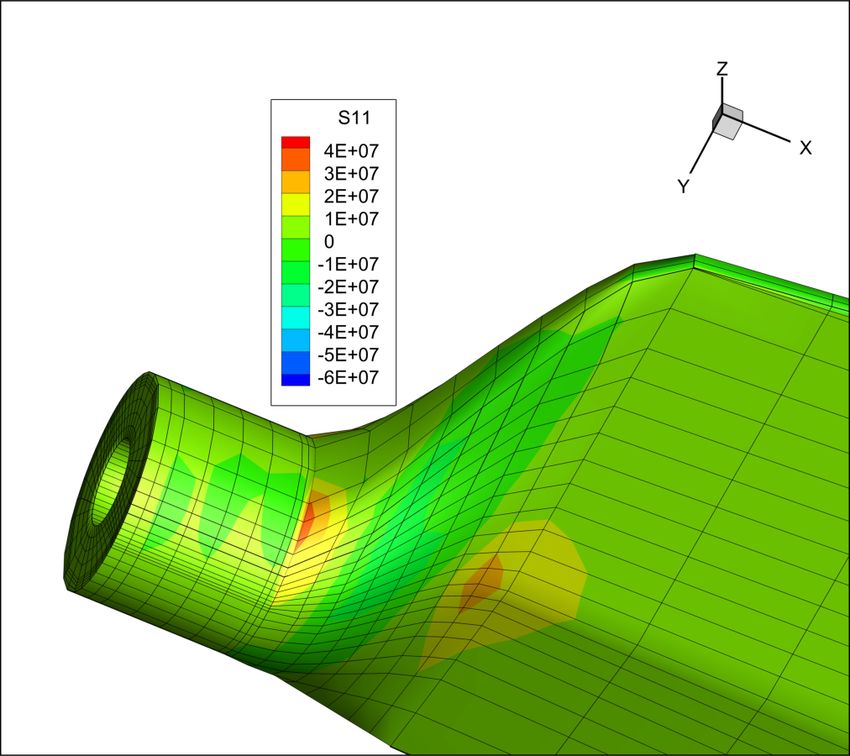
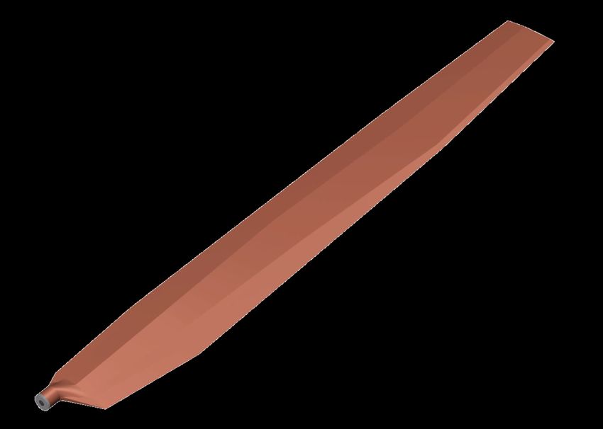
Blade Geometry Optimization
 The rotor performance in hover and forward flight were calculated using CAMRAD II, using the airfoil
table for the circular arc section (5% camber, 1% thickness). Planform taper and blade twist were varied to
minimize the rotor power required at the design conditions, keeping the blade thrust-weight solidity
constant. A square tip is needed so the tip vortex forms at the blade tip (not inboard), which gives the best
hover performance. The root cutout was 9%R. For a low Reynolds number, high-solidity rotor the
performance was not very sensitive to blade taper. Overall taper ratios from 0.5 to 1.0 were considered.
Reduced chord was considered for the root (negative taper, to 0.25R) to reduce weight, since inboard chord
is not very important for performance. Additional taper was considered at the tip (outboard of 0.75R). The
optimum linear taper was &'( / 500& = 0.85, with more taper at the tip (0.43) and reduced chord at the root.
Figure 17 shows the planforms for the coaxial helicopter blade and the hexacopter blade. As solidity
changed during the design process, the chord was scaled keeping the taper ratios constant.
 Large negative twist is good for hover and low speed rotor performance. Twist values from –12 to –24
deg (linear, root to tip) were considered, including different inboard and outboard twists. The optimum was
found to be –18 deg linear twist.
 The rotor performance was calculated for this optimum blade (airfoil, twist, and planform) with
CAMRAD II, and the results were used to calibrate the NDARC rotor performance model. Figure 18 shows
the NDARC results for the rotor power required of the Mars Science Helicopter. The larger total rotor disk
area of the hexacopter led to lower power required compared to the coaxial helicopter. The minimum power
speed was about 30 m/sec (best endurance speed). Best range speed was 50–60 m/sec. The corresponding
aircraft hover figure of merit was = 0.675 for the coaxial helicopter, and = 0.615 for the
hexacopter.

-0.05

 0.00
 coaxial helicopter blade
 0.05

 0.10

 0.15
 0.0 0.1 0.2 0.3 0.4 0.5 r/R 0.6 0.7 0.8 0.9 1.0

 -0.10

 0.00
 hexacopter blade
 0.10

 0.20
 0.0 0.2 0.4 r/R 0.6 0.8 1.0

 Figure 17. Mars Science Helicopter blade planform for four-bladed coaxial helicopter (radius = 1.25 m,
 solidity = 0.155) and four-bladed hexacopter (radius = 0.64 m, solidity = 0.193). The root cutout (not
 shown) is typically 9%R.

16
2500
 2500

 2000
 2000

 1500 1500

 power (W)
power (W)

 1000 1000
 coaxial hexacopter
 500
 500

 0
 0 0 10 20 30 40 50
 0 10 20 30 40 50 speed (m/sec)
 speed (m/sec) total induced profile ind+pro parasite

 Figure 18. Mars Science Helicopter forward flight performance.

 NDARC Models for Mars Helicopters
 The helicopters for the Mars science mission were sized using the rotorcraft design and analysis code
 NDARC. NDARC has detailed performance models of the rotor, battery, motor, and other components,
 with a detailed description of the mission. The rotor performance model was calibrated from CAMRAD II
 calculations of hover and forward flight performance for the optimized rotors (described above). Weight
 models were calibrated to the actual weights of the Mars Helicopter (Refs. 2, 15, 16), informed by the
 calculated weight of the MARV design (Ref. 7). Energy and power margins were based on the Mars
 Helicopter.

 Mission
 The payload of the Mars Science Helicopter was 2.02 kg, with a corresponding equipment power of 35
 W. In addition, there was 1.2 kg of avionics weight, including 0.1 kg for telecom and 0.1 kg for other
 equipment. The design included a contingency weight equal to 20% of the aircraft empty weight.
 The MSH design mission is shown in Figure 6: (a) 30 sec takeoff at hover power, (b) climb to altitude
 of 200 m, (c) 1 km flight to science site, (d) 2 min hover at science site, (e) land, (f) sleep for 1 sol, and
 recharge. The battery capacity was sized to the energy required for this mission, plus a reserve of 20% of
 the mission energy.
 The sleep energy was assumed to scale with aircraft length, hence with the 1/3 power of the gross
 weight: 6!,,( = 15 "/) Wh/sol (calibrated to MH), hence the sleep power was 6!,,( = 0.518 "/) W
 (for 1 sol = 1477 min, including battery efficiency of 85%). This power was modelled as equipment power,
 taking energy directly from the battery.

 Design Variables
 The design blade loading was / / = 0.11, which given the tip speed, air density, and rotor thrust
 determined the blade area. The design blade loading of the MH was / / = 0.10, allowing a 40% increase
 in thrust (beyond hover level flight) for control of the helicopter. Based on the measured and calculated

 17
thrust capability of the MH rotor (Figure 12) and the increased capability expected with the circular arc
airfoil (Figure 16), the design blade loading was increased by 10%.
 The hover tip Mach number was 0.7, based on the MH experience and the calculated airfoil behavior
at high Mach number. The speed of sound on Mars is 233.1 m/sec at –50 deg C, hence the tip speed at this
Mach number was 163.2 m/sec.
 The cruise flight speed was 30 m/sec, which was the minimum power speed (Figure 18). The flight
speed of the MH was much smaller, due to limitations of the visual navigation system. It was assumed that
the navigation system of the MSH supports flight speeds up to 50 m/sec. At 30 m/sec flight speed and tip
Mach number of 0.7, the advance ratio was / &'( = 0.18, and the advancing tip Mach number was -& =
0.83. That was a modest advance ratio, and the calculated airfoil characteristics show that the
compressibility limits were above that Mach number. If higher -& were possible (as below), the design
tip speed could be increased, and the blade area decreased, resulting in benefits for weight and performance.
Not much energy was used in cruise, so while flying faster (best range speed was above 50 m/sec) would
reduce the cruise power, the impact on the aircraft size would be small.

Motor
 For control authority and margin, the motors were sized to 150% hover power. The motors were
connected directly to the rotors, so the design motor speeds were about 1200 rpm (coaxial) and 3000 rpm
(hexacopter). The coaxial helicopter propulsion system would probably be lighter using a transmission. The
motor weight scaled with torque: +0&05 = 0.076 8.:; kg (current technology scaling, calibrated to MH).
The efficiency was constant at 68%, due to motor and electronic control system efficiency of 80% and rotor
control servo power equal to 15% of rotor power.

Solar Cell
 The solar cell power density was 540 Wh/m2/sol, or 21.9 W/m2 (based on MH). Charging 1.2 MJ in
one sol required a power of 13.54 W, hence a solar cell area of 0.62 m2 is required. The solar cell weight
density was 2.0 kg/ m2, hence the solar cell weight was 1.23 kg.

Battery
 The battery model was based on a JPL technology forecast. The weight was 278 Wh/kg cell, 230 Wh/kg
pack (including battery management system), 218.5 Wh/kg at end of life. The volume density was 420
Wh/L. The usable energy was 70% of the nominal capacity (10% to 80% depth-of-discharge). The MSH
required 1.2–1.4 MJ, hence had a battery weight of 1.5–1.7 kg. The efficiency of the battery was obtained
from the curve of voltage vs. state-of-discharge during various rates of discharge. This curve was obtained
from documented performance of current Li-ion batteries (specifically the MH battery). The resulting
discharge efficiencies were 88-92%. A mission time of 6 minutes implied an average discharge C-rate (1/hr)
of 10. That is a high discharge rate, within the capability of current batteries, but expected to reduce battery
life.

Drag
 The rotor propulsive power depends on the aircraft drag, which was calculated as the sum of
contributions from the fuselage, landing gear, rotor hub and pylon, and rotor support arms:
Fuselage: scale with wetted area, / = < =,& m2, < = 1.2, =,& = 27.5( /1000)#/) m2 (weight
in kg)
Landing gear: fixed, / = 0.05 m2

18
Rotors: scale with rotor disk area, / = L ?% + -A& = 0.15 kg each rotor (MH)
 Rotor support arms (hexacopter): scale with blade radius, 6?((05& = 0.2 kg each rotor
 (finite element model, MH rotor shaft)
 Fuselage Group: scale with gross weight, A?6,!-B, = 28( /1000)#/) (MH, in kg)
 Alighting Gear: scale with gross weight, B,-5 = 0.067 (MH)
 Propulsion
 Motor: scale with torque, +0&05 = 0.076 8.:; (MH)
 Solar Cell: scale with area, 2.0 kg/m2 (MH)
 Battery: JPL technology forecast, 218.5 Wh/kg (pack, including battery management system, end-
 of-life)
 Systems and Equipment
 Flight Controls: scale with blade weight, C0.&50! = 0.84 %!-$, (80% MH)
 Avionics: 1.2 kg (including 0.1 kg telecom, 0.1 kg other)
 Contingency: 20% Weight Empty
Payload: 2.02 kg

 Mars Science Helicopter Designs
 A coaxial helicopter and a hexacopter (Figure 19) were sized using NDARC to perform the Mars
Science Helicopter mission. Table 3 summarizes the aircraft characteristics, with the Mars Helicopter for
comparison. The rotor radius was maximized for the folded configuration. The hexacopter has more total
disk area than the coaxial helicopter, hence less energy required and less weight. The disk loading is high
(for the low density), which is reflected in the high solidity values. Table 4 shows the design mission
performance for the hexacopter. Most of the energy was expended in the hover segments. The high
discharge current (about 10C) probably reduces battery life.

 19
Figure 19. Mars Science Helicopter configurations, with Mars Helicopter (center) for scale.
 Table 3. Mars Science Helicopter designs.
 MSH MH Weights (kg)
 coaxial hex coaxial hex
 radius m 1.25 0.64 0.605 GROSS WEIGHT 18.032 17.662
 gross weight kg 18.03 17.66 1.80 WEIGHT EMPTY 16.012 15.646
 number rotors 2 6 2 STRUCTURE 5.858 6.405
 number blades 4 4 2 rotor group 2.724 3.322
 disk area m2 4.91 7.72 2.30 blade 1.755 1.719
 disk loading kg/m2 3.67 2.29 0.78 hub 0.902 0.883
 Re (75%R) 24752 15784 11412 shaft 0.068 0.086
 solidity 0.155 0.193 0.148 rotor support 0.634
 tip speed m/sec 163.17 163.17 163.17 fuselage group 1.925 1.899
 rotor speed rpm 1247 2435 2575 alighting gear 1.208 1.183
 motor power kW 3.17 3.32 0.36 PROPULSION 4.269 3.460
 solar cell m2 0.62 0.62 0.04 motor 1.345 0.741
 battery Ah 128 113 12 solar cell 1.197 1.197
 battery 1.727 1.522
 SYS & EQUIP 2.674 2.644
 drag m2 0.481 0.492 flight controls 1.474 1.444
 avionics 1.200 1.200
 CONTINGENCY 3.200 3.127
 PAYLOAD 2.020 2.020

 Table 4. Design mission performance (hexacopter).
 Design Mission time distance speed energy energy (%) current
 min m m/sec MJ 1/hr
 takeoff 0.5 0 0 0.0863 12% 9.4
 climb to 200m 0.33 0 0 0.0693 10% 11.8
 fly to site 0.56 1000 30 0.0784 11% 7.9
 hover at site 2 0 0 0.3486 50% 9.9
 sleep 1 sol 1477 0 0 0.1161 17% 0.005

20
Blade Structural Analysis
 The blade structure was analyzed using the three-dimensional finite element analysis code X3D. X3D
can calculate the stress and strain of the rotating structure under loading, and it can obtain the natural
frequencies of vibration. The blades of the coaxial helicopter and the hexacopter were analyzed at the design
rotational speed and for a rotor speed sweep. The blades had the cambered plate airfoil (5% camber, 1%
thickness ratio), and the optimized twist and taper (Figure 17). The root cutout was 9%R. The material was
carbon fiber 60 gsm HR40 spread tow Bi-D carbon fiber with a reduction of material stiffness consistent
with the MH design.
 The target blade flap frequency was 1.5/rev at the design rotational speed. This requirement was based
on the stability margin for control, as discussed below. The root thickness was increased as required to
achieve this stiffness. The following blade designs were analyzed:
 a) Coaxial helicopter: thickness ratio t/c = 12% at 20%R (root cutout) to 1% at 45%R to tip.
 b) Hexacopter: thickness ratio t/c = 6% at 22%R (root cutout) to 1% at 50%R to tip.
 c) Hexacopter: thickness ratio t/c = 1% over entire blade (blade flap frequency fallout).
For comparison, the MH blade is similar to a conventional propeller design: thickness ratio t/c = 96% at
9%R, t/c = 22% at 20%R, t/c = 5% at 48%R to tip (CLF5605 airfoil).
 Figure 20 shows the calculated strain in blade during flap motion and the blade frequencies as a function
of rotor speed. The lowest blade frequency is for the flap mode. The light lines are constant per-rev values,
and the flap frequency was 1.5/rev at the design rotational speed (1247 rpm for coaxial, 2435 rpm for
hexacopter). The strain plots show that this flap frequency was achieved by making the inboard part of the
blade stiff, so there was an effective flap hinge at about 45%R. The structural analysis gave an estimate of
the blade weight: 492 g for the coaxial blade, and 70 g for the hexacopter blade. These estimates were not
used to update the NDARC designs, but eventually the results of the rotor structural design and analysis
must be used to revise the NDARC blade weight models.

 Flight Dynamics and Control

Helicopter Control
 Helicopter rotors are controlled by collective (mean) and cyclic (once-per-revolution) changes in the
blade pitch (Ref. 18). Collective pitch changes the rotor thrust, and cyclic pitch (cosine and sine harmonics)
produces hub moments and tilt of the thrust vector (about two axes). Usually the pitch motion is rotation
about a bearing at the blade root. A swashplate mechanism transforms three controls (collective, lateral
cyclic, and longitudinal cyclic) from the pilot or actuators into rotating frame mean and 1/rev pitch bearing
motion.
 Controlling the rotorcraft requires the ability to produce roll, pitch, and yaw moments on the aircraft,
and a vertical force. A coaxial helicopter has collective and cyclic controls on both rotors. Changing the
collective of both rotors produces the vertical force, and differential collective change produces a yaw
moment. Cyclic control to both rotors produces pitch and roll moments. It is possible to control the
helicopter using cyclic on only one of the coaxial rotors, but that results in half the control power and
undesirable coupling between the control modes.
 A hexacopter has collective control on each rotor, without rotor cyclic. Changing the collective of all
rotors produces the vertical force, and differential collective (based on rotor rotation direction) produces a
yaw moment. With four rotors, there is a unique combination of thrust changes on the rotors that produces
pitch or roll moment with no net vertical force or yaw moment. With six rotors, there is an optimum way
to produce the moments on the aircraft (which would change if one or two of the rotors became inoperative).

 21
You can also read