M9601A PXIe Precision Source/Measure Unit - Keysight
←
→
Page content transcription
If your browser does not render page correctly, please read the page content below

M9601A
PXIe Precision Source/Measure Unit
1.25 MSa/s, 10 fA, 210 V, 315 mA

The industry high-performance PXIe SMU enabling faster
precise dynamic measurement from DC to 20 µs pulse,
output up to 210 V/315 mA, and with the best-in-class 10 fA
resolution and lowest source noise

Find us at www.keysight.com                                   Page 1

Table of Contents
Introduction.................................................................................................................................................... 3
Overview ....................................................................................................................................................... 4
   Integrated source and measurement capabilities simplify challenging IV measurement tasks ................ 4
   Low current measurement noise performance reduces the measurement time ...................................... 5
   Narrow pulse suppresses self-heating effect ............................................................................................ 6
   Fast transient captures the actual transient response from the devices and circuits ............................... 7
   Drivers and soft front panel ....................................................................................................................... 8
   PX0109A Quick I/V Measurement Software, essential and powerful software tool to control the PXIe
   Precision SMU .......................................................................................................................................... 9
Specifications .............................................................................................................................................. 11
   Specification conditions ........................................................................................................................... 11
   Maximum voltage and current ................................................................................................................. 11
   Source/measurement specifications and characteristics ........................................................................ 12
Other Supplemental Characteristics ........................................................................................................... 17
Environmental Specifications ...................................................................................................................... 18
Source/Measurement Capabilities .............................................................................................................. 18
System and Installation Requirements for PX0109A .................................................................................. 19
Furnished Accessories ................................................................................................................................ 19
Ordering Information ................................................................................................................................... 20

Find us at www.keysight.com                                                                                                                                          Page 2

Introduction
The Keysight M9601A PXIe precision source/measure unit is a precision source/measure unit (SMU)
with the capability to source and measure both voltage and current. It covers currents from 10 fA to
315 mA and voltages from 500 nV to 210 V. It can make precise measurements broadly from DC to
pulsed down to 20 μs pulse width with the sampling rate up to 1.25 MSa/s. The M9601A is ideal for a
wide variety of current versus voltage (IV) measurement tasks that require both high resolution and
accuracy such as the characterization, parametric/reliability tests of semiconductors, active/passive
components, and general electronic devices.

                     Feature                                               Benefit
                                                  Easily and accurately measures current and voltage
  Integrated symmetry 4-quadrant sourcing
                                                  using a single module without the need to change any
  and measuring capabilities
                                                  connections manually
                                                  Single SMU module covers both voltage and current
  Wide voltage and current coverage:
                                                  measurement requirements, allowing for standardization
  ± 210 V, ± 315 mA
                                                  and simplifying inventory and support concerns
  Source and measurement resolution down          Makes low-level measurements using a PXIe SMU
  to 10 fA and 500 nV                             module
                                                  Reveals more of the true characteristics of the devices
  Low current measurement noise: 30 fArms
                                                  with less aperture time, which improves measurement
  at 1PLC
                                                  throughput
                                                  Suppresses self-heating effect and has the true
  Narrow pulse capability: 20 μs                  characteristics of the devices to improve measurement
                                                  throughput
                                                  Captures the actual transient response from the devices
  Fast transient capability: 1.4 V/μs slew rate
                                                  and circuits without the influence of the measurement
  at maximum
                                                  equipment’s performance
  High-speed sampling measurement:                Captures dynamic behavior and response to the pulsed
  1.25 MSa/s sampling rate, 1 Mpts memory         signal of the devices and circuits in a single
  depth                                           measurement

Find us at www.keysight.com                                                                                 Page 3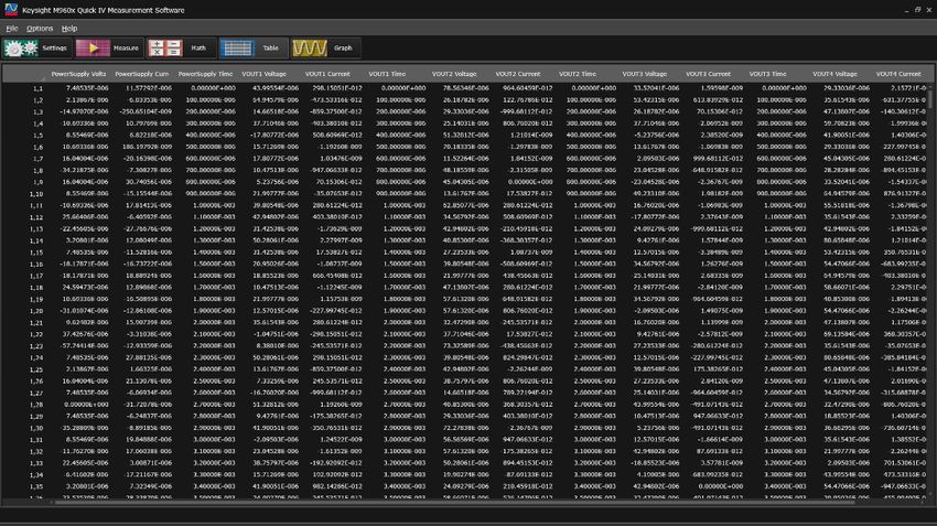
Overview
Integrated source and measurement capabilities simplify challenging IV measurement tasks
The M9601A PXIe SMU integrates different source and measurement capabilities into one PXIe module
(please see Figure 1). It can operate as a seamless symmetry 4-quadrant precision voltage/current
source, an electrical load, an accurate voltage/current meter, and a pulse generator. Its versatile all-in-
one integrated source and measurement capabilities allow it to perform a wide variety of measurements
from DC to pulsed without the need to change connections or use additional equipment.

Since SMUs can very accurately measure their current and voltage output, they have many advantages
over conventional power supplies. All SMUs have internal feedback loops that provide instantaneous
feedback to the sourcing circuitry, which allows the SMU output to remain accurate and stable even if
the load conditions change unexpectedly.

SMUs also possess a voltage and current limit (compliance) feature that allows you to set limits to
protect devices from damage caused by excessive voltage or current.

Figure 1. Simplified block diagram of the M9601A

Find us at www.keysight.com                                                                                   Page 4

Low current measurement noise performance reduces the measurement time
The low measurement noise performance is important for the low-level measurement as well as the high
measurement resolution capability. The long aperture time is commonly used to eliminate the
measurement noise, especially for small current measurement, but the measurement time becomes
longer accordingly. The Keysight M9601A can achieve 30 fArms noise level with 1 power line cycle
(PLC) aperture time (at 50 Hz power line frequency), which is three times lower than the conventional
PXIe SMU under the same condition (aperture time) and 10 times faster than the conventional PXIe
SMU module to achieve the same level noise (please see Figure 2 and 3). This capability enables you to
reveal more of the true characteristics of your devices and shorten the measurement time significantly.

      Keysight
      M9601A
  Conventional
    PXIe SMU

           0 fArms     40 fArms     80 fArms     120 fArms
                     Current measurement noise

Figure 2. Current measurement noise with 1 PLC (20 ms) aperture time

      Keysight
      M9601A
  Conventional
    PXIe SMU

           0 PLC        4 PLC         8 PLC        12 PLC
                            Aperture time

Figure 3. Aperture time required to achieve 30 fArms current measurement noise

Find us at www.keysight.com                                                                               Page 5
Narrow pulse suppresses self-heating effect
The M9601A can make precise measurement broadly from DC to pulsed down to 20 μs pulse width with
the sampling rate up to 1.25 MSa/s, which makes the M9601A ideal for a wide variety of current versus
voltage (IV) measurement tasks that require both high resolution and accuracy (please see Figure 4).
The narrow pulse capability down to 20 μs width enables you to suppress the self-heating effect to
reveal the true characteristics of the devices.

Figure 4. Narrow pulse down to 20 μs enables you to suppress self -heat effect to reveal the true
characteristics of the devices

Find us at www.keysight.com                                                                             Page 6

Fast transient captures the actual transient response from the devices and circuits
Commonly, the slew rate of the conventional SMUs varies with the measurement conditions, which
affects the measurement results. The M9601A has two operation modes such as standard mode (works
the same as a conventional SMU) and the PS mode which enables fast transient with 1.4 V/μs slew rate
at maximum (please see Figure 5). The unmatched fast transient capability enables you to capture the
actual transient response from the devices and circuits without the influence of the measurement
equipment’s performance.

Figure 5. A voltage of 200 V ramped up to within 150 μs

Find us at www.keysight.com                                                                            Page 7
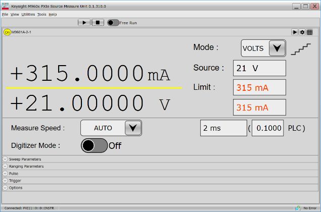
Drivers and soft front panel
The M9601A comes complete with software drivers for Microsoft Windows 7 Professional SP1 or later
(32-bit/64-bit), Microsoft Windows 8.1 Professional or later (32-bit/64-bit), Microsoft Windows 10
(32-bit/64-bit). These software drivers work in the most popular test and measurement development
environments, including Visual Studio (VB.NET, C#, C/C++), LabVIEW, MATLAB, VEE.

Standard Commands for Programmable Instruments (SCPI) are a popular and easy-to-understand
instrument control protocol. The M9601A supports it as well, which will minimize code conversion work
from the existing benchtop-based test system.

The soft front panel provides easy to use instrument control (please see Figure 6). Its user-friendly
graphical user interface guides developers through module setup so users can quickly configure the SMU.

Figure 6. M9601A soft front panel

Find us at www.keysight.com                                                                             Page 8
PX0109A Quick I/V Measurement Software, essential and powerful software tool to control the
PXIe Precision SMU
The Keysight PX0109A Quick I/V Measurement Software for PXIe Precision SMU has powerful
measurement capabilities to control the M9601A, M9602A, M9603A, M9614A and M9615A. It supports
a variety of functions such as a sweep measurement, a sampling measurement, graphical display
functions and the ability to save test results into CSV files, which makes it easy to quickly setup and
perform current-voltage (IV) measurements and to display the measurement data in tables and graphs
without the need to program. It is licensed based and the licenses are sold as node-locked, floating,
transportable and USB portable.

The PX0109A Quick I/V also allows you to control up to ten SMU channels so that you can measure
devices or circuits requiring more than two SMU channels for characterization, verification, or test. In
addition, the PX0109A Quick I/V has the capability to make not only primary sweep measurements but
also measurements where a second terminal is swept, making it easy to generate a variety of IV curves.

The setup menu allows you to specify and preview the settings on up to ten SMU channels before you
perform a measurement, giving you the flexibility and ease of setting up the SMU channels.

Find us at www.keysight.com                                                                                Page 9
The built-in graph function supports both basic and advanced features (such as the family of curves
shown here).

Numerical measurement results can be viewed in a table format, and this data can easily be copied into
Excel for further analysis.

For free 30-day trials, visit: www.keysight.com/find/px0109a

Find us at www.keysight.com                                                                              Page 10
Specifications
Specification conditions
The measurement and programming accuracy are specified at the front panel connector terminals.
Accuracy is specified under the following conditions.

  Temperature             23 °C ± 5 °C (double for 5 °C to 18 °C, and 28 °C to 40 °C unless noted otherwise)
  Humidity                20% to 60% RH (double for 60% to 70% unless noted otherwise)
  Warm-up time            40 minutes
                          Performed within the last 24 hours
  Self-calibration
                          Ambient temperature changes less than ± 5 °C after self-calibration execution
  Calibration period      One year
                          1 PLC1 (100 nA to 300 mA ranges, voltage ranges)
  Aperture time
                          10 PLC (1 nA and 10 nA ranges)
  Terminal
                          Kelvin connection
  connection
 1.   Power line cycle.

Maximum voltage and current
              Maximum voltage                     Maximum current                   Maximum power
  ± 21 V                                ± 315 mA                           6.6 W
  ± 105 V                               ± 105 mA                           11 W
  ± 210 V                               ± 50 mA                            10.5 W

Find us at www.keysight.com                                                                                    Page 11
Source/measurement specifications and characteristics
Voltage source/measurement specifications
Programming and measurement Source noise
Range (peak to peak) Max current
Resolution Accuracy (% of reading + offset) 0.1 Hz to 10 Hz 1
± 0.5 V 0.5 μV ± (0.015% + 120 μV) ≤ 4 μV ± 315 mA
±2V 2 μV ± (0.015% + 140 μV) ≤ 5 μV ± 315 mA
±6V 6 μV ± (0.015% + 250 μV) ≤ 5 μV ± 315 mA
± 20 V 20 μV ± (0.015% + 900 μV) ≤ 15 μV ± 315 mA
± 40 V 40 μV ± (0.015% + 1 mV) ≤ 30 μV 2
± 100 V 100 μV ± (0.015% + 2.5 mV) ≤ 60 μV 2
± 50 mA (100 mA
± 200 V 200 μV ± (0.015% + 2.8 mV) ≤ 100 μV
or less ranges)
1. Supplemental characteristics, 0 V sourced, 10 mA or less ranges .
2. ± 315 mA (-21 V ≤ V o ≤ 21V), ± 105 mA (V o < -21 V, V o > 21 V).
Current source/measurement specifications
Programming and measurement Source noise
Range (peak to peak) Max voltage
Resolution Accuracy (% of reading + offset) 0.1 Hz to 10 Hz 1
± 1 nA 10 fA ± (0.1% + 1.5 pA + 1 fA x Vo) 2 ≤ 200 fA ± 210 V
± 10 nA 10 fA ± (0.1% + 3 pA + 10 fA x Vo) 2 ≤ 200 fA ± 210 V
± 100 nA 100 fA ± (0.05% + 20 pA) ≤ 2 pA ± 210 V
± 1 μA 1 pA ± (0.05% + 100 pA) ≤ 2 pA ± 210 V
± 10 μA 10 pA ± (0.04% + 2 nA) ≤ 80 pA ± 210 V
± 100 μA 100 pA ± (0.03% + 3 nA) ≤ 90 pA ± 210 V
± 1 mA 1 nA ± (0.03% + 60 nA) ≤ 8 nA ± 210 V
± 10 mA 10 nA ± (0.03% + 200 nA) ≤ 10 nA ± 210 V
± 100 mA 100 nA ± (0.04% + 6 μA) ≤ 200 nA 3
± 21 V (100 V or
± 300 mA 300 nA ± (0.04% + 20 μA) ≤ 1 μA
less ranges)
1. Supplemental characteristics, 0 A sourced.
2. Aperture time: 10 PLC.
3. ± 210 V (-50 mA ≤ I o ≤ 50 mA), ± 105 V (I o < -50 mA, I o > 50 mA).
Find us at www.keysight.com Page 12Source supplemental characteristics
11 W
Max output power and
± 21 V at ± 315 mA, ± 105 V at ± 105 mA, ± 210 V at ± 50 mA, four quadrant
source/sink limits
source or sink operation
Accuracy is same as current source; minimum value is
Current compliance
1% of range (100 nA to 300 mA ranges)
setting accuracy
1 nA (1 nA, 10 nA ranges)
Accuracy is same as voltage source; minimum value is
Voltage compliance
1% of range (6 V to 200 V ranges)
setting accuracy
50 mV (500 mV, 2 V ranges)
105% of voltage source range for all voltage ranges
Over range 105% of current source range for 300 mA range
115% of current source range for ranges other than 300 mA range
Over-temperature
Output turns off then resets at over temperature sensed internally.
protection
< 45 μs (500 mV to 40 V ranges, open load)
< 100 μs (100 V range, 100 kΩ load)
Voltage output settling
< 200 μs (200 V range, 100 kΩ load)
time
Time required to reach within 0.1% of final value at described load condition;
step is 10% to 90% range with 10 mA compliance, filter auto settings
1.5 V/μs (PS mode with 50 mA compliance)
Slew rate 2 1 V/μs (Standard mode with 10 mA compliance)
Step is 0 V to 200 V at open load condition
< 18 ms (1 nA, 10 nA ranges, 50 MΩ load)
< 1.2 ms (100 nA, 1 μA ranges, 500 kΩ load)
< 400 μs (10 μA, 100 μA ranges, 5 kΩ load)
< 70 μs (1 mA range, 50 Ω load)
Current output settling
< 40 μs (10 mA range, 50 Ω load)
time
< 40 μs (100 mA range, 500 mΩ load)
< 40 μs (300 mA range, 100 mΩ load)
Time required to reach within 0.1% 1 of final value at described load
condition; step is 10% to 90% range with 6 V compliance, filter auto settings
V source noise < 3 mVrms, < 25 mVp-p, 20 V range (10 mA or less ranges)
(BW = 20 MHz) < 6 mVrms, < 40 mVp-p, 20 V range (100 mA, 300 mA ranges)
V source noise
< 5 mVrms, < 50 mVp-p, 20 V range
(BW = 200 MHz)
Voltage range switching
< 250 mV, 100 kΩ load, 20 MHz bandwidth
transient noise
Current range switching
< 70 mV, 100 kΩ load, 20 MHz bandwidth, V source mode, 20 V range
transient noise
1. 0.3% for 100 mA, 300 mA ranges.
2. Observed data.
Find us at www.keysight.com Page 13Pulse source supplemental characteristics
Programmable pulse width 20 μs to 1 s
Minimum pulse width programming resolution 0.2 μs
Pulse width programming accuracy 0.5 % ± 2 μs
Pulse period programming accuracy 0.5 % ± 4 μs
The time from 10% leading to 90% trailing edge
Pulse width definition
(Figure 7)
Peak level Pulse width Transition time
Base level
Figure 7. Definition of the pulse parameters and the transition time
Transition time at the given voltage, current and settling conditions (observed data)
Source settling band
Source value Limit value Operation mode Load Transition time
(% of range)
200 V 50 mA Standard 100 kΩ 0.1% 2.5 ms
200 V 50 mA PS 100 kΩ 0.1% 140 μs
300 mA 6V Standard 100 mΩ 0.3% 40 μs
Transition time definition: The time from “Source settling band” to “100% - Source settling band” leading
edges (Figure 7).
Measurement supplemental characteristics
105% of voltage measurement range for 200 V range
110% of voltage measurement range for ranges other than 200 V range
Over range
105% of current measurement range for 300 mA range
115% of current measurement range for ranges other than 300 mA range
Find us at www.keysight.com Page 14Voltage measurement noise (observed data) Figure 8. Voltage measurement noise vs. measurement aperture time Current measurement noise (observed data) Figure 9. Current measurement noise vs. measurement aperture time Find us at www.keysight.com Page 15
Measurement noise – no load (observed data)

Figure 10. Measurement noise, 10 nA range, no load, 0 V, triax cable (3 m)

Measurement noise – 1 GΩ load (observed data)

Figure 11. Measurement noise, 10 nA range, 1 GΩ load, 9 V, triax cable (3 m)

Find us at www.keysight.com                                                    Page 16
Measurement and timing characteristics
  Available sampling rates                                     (1.25 MSa/s)/N where N=1, 2, 3, …, 224
                                                               Frequency accuracy is inherited from
  Sample rate accuracy
                                                               PXIe_CLK100
  Maximum source update rate                                   250 kSa/s
                      Source/sense trigger delay               ≤ 5 μs
  Input trigger to
                      Source/sense trigger jitter              ≤ 4 μs

Other Supplemental Characteristics
                                                      Timer
                                       Timer value automatically saved when each measurement is
  Timestamp
                                       triggered
  Trigger timing resolution            4 μs to 100 ms
  Clock source                         PXIe_CLK100
  Arm/trigger delay                    0 μs to 100,000 s
  Arm/trigger interval                 4 μs to 100,000 s
  Arm/trigger event                    1 to 1,000,000 (count)
                                                  Input triggers
  Sources (PXI trigger lines 0 to 7,   Polarity                           Configurable
  external trigger 0 and 1)            Minimum pulse width                200 ns, nominal
                                                Output triggers
                                       Polarity                           Configurable
  Destinations (PXI trigger lines
                                                                          Configurable between 200 ns and
  0 to 7, external trigger 0 and 1)    Pulse width
                                                                          12.8 μs, nominal
                                              Output characteristics
  Sensing modes                        2-wire or 4-wire (remote-sensing) connections
  Low terminal connection              Chassis grounded or floating
                                       Triaxial jack for high force and high sense
  Output connectors
                                       SMB jack for low sense
  Maximum guard offset voltage         < 2 mV
                                       Max voltage between high force and high sense = 1 V
  Remote sense operation range
                                       Max voltage between low force and low sense = 1 V
  Voltage source output resistance     < 0.3 Ω (non-kelvin)
  Current source output resistance     ≥ 10 TΩ (1 nA range)
  Maximum allowable cable              Sense: 10 Ω
  resistance                           Force: 10 Ω (Io ≤ 100 mA), 3 Ω (Io > 100 mA)
  Maximum load capacitance             100 μF (100 mA to 300 mA ranges, ESR ≥ 25 mΩ)
  Guard output impedance               610 Ω (nominal)
  Maximum DC floating voltage          ± 40 V between low force and chassis

Find us at www.keysight.com                                                                             Page 17
Environmental Specifications
Environment For use in indoor facilities
Operating 5 °C to 40 °C, 15% to 70% RH, non-condensing
Storage -20 °C to 60 °C, 5% to 90% RH, non-condensing
Altitude Operating: 0 m to 2000 m; storage: 0 to 4600 m
+ 3.3 V ± 5%, 1.5 A
Power consumption
+ 12 V ± 5%, 3.5 A
IEC61326-1/EN61326-1, IEC61326-2-1/EN61326-2-1, CISPR
EMC 11/EN55011 Group 1 Class A, ICES-001, AS/NZS CISPR11,
KN61000-6-1, KN11
IEC61010-1/EN61010-1, IEC61010-2-030/EN61010-2-030,
Safety
CAN/CSA-C22.2 No. 61010-1, CAN/CSA-C22.2 No. 61010-2-030
Compliance and Certifications CE, cCSAus, C-Tick, KC
Warm-up 40 minutes
3U, 2-slot PXIe module
Dimensions
Height 40.1 mm x depth 131 mm x width 210 mm
Weight 0.55 kg
Source/Measurement Capabilities
Sweep measurement
Number of steps 1 to 1,000,000
Sweep mode Linear or list
Sweep direction Single or double
Type DC or pulse
Min programmable value to create
4 µs
list sweep waveform
Digitizing/sampling measurement
Max sampling rate 1.25 MSa/s
Data buffers
Max buffer size 1,000,000 points
Program, software, and drivers
Programming SCPI (Rev 4.0 or later)
Microsoft Windows 7 Professional SP1 or later (32-bit/64-bit)
Supported operating systems Microsoft Windows 8.1 Professional or later (32-bit/64-bit)
Microsoft Windows 10 (32-bit/64-bit)
Standard compliant drivers IVI-C, IVI.Net, LabVIEW
Supported application development
Visual Studio (VB.NET, C#, C/C++), LabVIEW, MATLAB, VEE
environment (ADE)
.NET Framework Microsoft .NET Framework 4.5.2 or later
Keysight IO libraries Keysight IO Libraries Suite 2019 or later
Find us at www.keysight.com Page 18System and Installation Requirements for PX0109A
Computer operating system
Operating system Windows 10 (64-bit) Pro, Windows 10 (64-bit) Enterprise
Supporting language English (US)
.NET Framework Microsoft .NET, Framework 4.7.1
IO Libraries Keysight IO Libraries Suite 2019 or later
PathWave License Manager 2.4.1 or later
Interfaces PXIe
Furnished Accessories
Furnished accessories
Short bar, connector-terminal block 2.5 mm 6-terminal, certificate of calibration (without test data), quick
startup poster
Find us at www.keysight.com Page 19Ordering Information
Model number
M9601A PXIe precision source/measure unit, 1.25 MSa/s, 10 fA, 210 V, 315 mA
Options
1A7 Calibration + uncertainties + guardbanding (not accredited)
A6J ANSI Z540-1-1994 calibration
UK6 Commercial calibration certificate with test data
Accessories
PX0101A-001 BNC to ferrule terminal cable, 1.5 m
PX0101A-002 BNC to ferrule terminal cable, 3 m
PX0102A-001 Low noise triaxial cable, 1.5 m
PX0102A-002 Low noise triaxial cable, 3 m
PX0103A-001 Triaxial to SMB cable, 1.5 m
PX0103A-002 Triaxial to SMB cable, 3 m
Software
Product License type License term (36 months subscription)
License & support
Node-locked (fixed) R-X45-001-Y
Transportable R-X45-004-Y
PX0109A USB Portable1 R-X45-005-Y
Floating (single site) R-X45-002-Y
Floating (single region) R-X45-006-Y
1. USB portable license requires a certified USB dongle (available for additional purchase. Keysight part number PX0100 -D10)
Learn more at: www.keysight.com
For more information on Keysight Technologies’ products, applications, or services,
please contact your local Keysight office. The complete list is available at:
www.keysight.com/find/contactus
Find us at www.keysight.com Page 20
This information is subject to change without notice. © Keysight Technologies, 2020 - 2021, Published in USA, September 10, 2021, 5992-4192ENYou can also read