Loudspeaker Active Spectral Divider Design Project - Purdue Engineering
←
→
Page content transcription
If your browser does not render page correctly, please read the page content below

ECE 40020                    Sound Reinforcement System Design                     Spring 2018

        Loudspeaker Active Spectral Divider
                 Design Project

From left to right: AJ “Andrew Jackson, 7th President of the United States” Trent, Frank “The
Tank” Kim, Oscar “Orthogonal Olive Oil” Otero, Joe “Trying to Entertain Himself” Coleman
ECE 40020                      Sound Reinforcement System Design                         Spring 2018

            Project Report Evaluation – Team ID: 02

       Team Member               1.0     2.0      3.0     4.0    App     Tech     TOTAL
                                                                          *
Tae Hyun Kim (Frank)
Joe Coleman
AJ Trent
Oscar Otero

 Maximum Points Possible         10       30      10      10      20         20    100
* technical content, writing style, professionalism, clarity, completeness

Instructor comments:

______________________________________________________________________________

______________________________________________________________________________

______________________________________________________________________________

______________________________________________________________________________

______________________________________________________________________________

______________________________________________________________________________

______________________________________________________________________________

                                                 2
ECE 40020               Sound Reinforcement System Design            Spring 2018

                         TABLE OF CONTENTS

Abstract                                                                     i
 1.0 Introduction                                                           1

 2.0 Design Narrative                                                       ?
 3.0 Results                                                                ?
 4.0 References                                                             ?
Appendix A: Activity Logs                                                   ?
Appendix B: Schematic (Analog) or Tuning Parameters (DSP)                   ?
Appendix C: Frequency Response Measurement                                  ?

Appendix D: Subwoofer Design Documentation                                  ?

Abstract
Your job is to design an active 3-way spectral divider (crossover network) for a
“stock” 3-way (tri-amplified) labyrinth loudspeaker system. Both the loudspeaker
system and class D amplifier modules (4 x 100W) with power supply will be
provided. Your spectral divider can either be analog (op amp based) or digital
(DSP based, implemented using a “stock” microcontroller development board).
Level controls should be provided for each loudspeaker output drive. Primary
goals including optimizing frequency response (target ±3 dB over the range of 40
Hz to 16,000 Hz) and minimizing THD (total harmonic distortion). For bonus
credit an (add-on) subwoofer can be designed and constructed, which will require
a 4-way spectral divider.

                                       3
ECE 40020                      Sound Reinforcement System Design                         Spring 2018

1.0 Introduction

Tae Hyun Kim (Frank):
I’m a senior in electrical engineering and I am focusing my study in power electronics. However,
I worked with audio engineering for hobby since I was young age. Before coming to Purdue, I
made my own stereo system amplifier and speaker during my free time and I wanted to take
ECE40020 for fun before graduation. However, I may not have same experience or knowledge
with other people in this class but I am willing to learn more materials so I can “expand” my
knowledge into wide area of sound engineering.

Joe Coleman:
I’m currently a senior in Electric Engineering. Basically, I took this class as result of my interest
in this subject, and wanted to explore more into sound and speaker design. With my education
that I have received so far, I was very interested in seeing how I could apply my electrical
engineering knowledge to this project. When we decided to make an analog crossover filter,
versus a digital one, for this project, I was excited to be able to apply my circuitry knowledge to
this course. Through this class, I hope to expand my knowledge on sound design, and use this to
further my enjoyment of my hobby. Potentially, one day, I hope to end up in some sort of audio
consumer-product related field.

AJ Trent:
I’m a current junior majoring in Acoustical Engineering and minoring in ECE and Sound for the
Performing Arts, and outside of my academic connection to audio, I’m a musician and long time
audiophile. ECE 40020 is likely the single most applicable class at Purdue to those interests, and
so it was an obvious choice as one of my upper level ECE credits. This project has already
served as a connecting link between some of my earlier coursework and has given me the
opportunity to dive into the basics of the industry I plan to get into after graduation, audio
electronics design.

Oscar Otero:
I am currently a Junior in Acoustical Engineering. Through my internships and personal studies,
most of my breadth of knowledge pertains to architectural acoustics. However, I am interested in
sound in all its applications, so I took this course so I could learn more about the electrical side
of sound and audio. Through this project, I have learned much about the physics behind speaker
enclosures, as well as much more about the circuitry behind filters for an analog system. While I
am excited to increase my knowledge in the audio side of sound, I still hope to make a career in
architectural acoustics. However, the knowledge obtained from this class will help me
communicate with the audio engineers I will likely work with in the future.

                                                  4
ECE 40020                     Sound Reinforcement System Design                       Spring 2018

2.0 Design Narrative

Analog Crossover Design

         When the group first started our design process, we were given a stock 3-way labyrinth
loudspeaker system. Our design process, however, differed greatly from the other three groups.
Our system would be an analog system, which meant that we would have to design our crossover
filters ourselves. This meant that the tuning process would be much more labor intensive and
less opportunities for trial and error adjustment would be available. This obstacle was kept in
mind throughout the planning and design process.

        Before we began our actual design process, it was important to assess the stock
loudspeaker system we were given. In our initial subjective listening tests of the stock
loudspeaker system, we found that the system sounded too harsh in the higher frequencies, which
we determined to be a downside of the hard dome tweeter installed in our cabinet. To remedy
this and shoot for a less “tinny” and fatiguing sound we decided to swap the original tweeter out
for a soft dome tweeter available in the lab, which we felt would help improve our sound from
the start and better match our subjective preferences. We also felt that the cabinet was lacking
low end power and extension and decided to design and build an external subwoofer as well.

        Because we designed a passive crossover network, our process included less trial and
error and relied more heavily on research and analysis of the speakers’ frequency responses and
usable ranges. For example, based on the response curves provided, the woofer can produce
frequencies down to about 70 Hz. To ensure a smooth crossover and avoid distortion in the
woofer and port noise in the subwoofer, we settled on a crossover point of 80 Hz with a filter
slope of 12 dB/octave. A similar approach was used to select the crossover points between the
woofer, midrange driver, and tweeter.

        When choosing what crossover frequencies and gains for our analog filter, we first
considered looking at the frequency response of our drivers. Our group noted a few
characteristics of the frequency response of all three drivers that we prioritized when choosing
our crossovers and dB gains. First, we noted the large peak in the midrange driver at around 500
Hz, so in order to counter this peak, we decided to have the crossover between the woofer and
squawker at 800Hz. Second, we noted that the squawker rolled off at around 3 KHz, with as well
as the tweeter beginning to level off. This frequency would be noted as the crossover frequency
between the squawker and tweeter. Third, our group noticed a dip in dB around 2 Khz for the
squawker, so in order to counteract this dip, we would aim to increase the gain around that area.
Finally, we desired to crossover with our designed subwoofer at 80 Hz.

       Once we choose our desired frequencies and gains, it was time to design how to
implement this filter. Our choice of filter ended up being 2nd-order Butterworth filters for both
our high-pass and low-pass cutoffs. For each driver, the signal would be passed through one or
more 2nd-order Butterworth filters, and from there the signal would enter a TL074C operational
amplifier. These op amps would be placed in non-inverting configuration, with the resistor
values of our op amp circuit determining the gain of the filtered signal. This gain would have the
value of 1 plus the ratio of the output to grounded resistor. The output signal of the amplifier
would be passed through a small resistor, where it then enters its specific driver. Along with our
LPFs and HPFs, if a driver needed more than one filter, we would need a inverting op amp with

                                                5
ECE 40020                       Sound Reinforcement System Design                         Spring 2018

a gain inverted to contrast the filters’ gains before the signal passes through the crossover filters.
This is due to Butterworth filters causing a 90° phase shift of the signal, but in opposite
directions for the LPFs and HPFs.

        From our desired frequencies and gains, we were able to calculate the components
needed for both our 2nd-order Butterworth HPFs and LPFs. Across our circuit, we would use
10nF capacitors for our filters, though our resistor values would vary. For our woofer, we had
our LPF with a 20 kΩ resistor and a HPF with a 200 kΩ resistor, to reach our desired crossovers.
Our op amps, both inverting and non-inverting, would have an input resistor of 10 kΩ and output
of 8200 Ω. For our squawker, we had our LPF with a 5820 Ω resistor and a HPF with a 20 kΩ
resistor. Our op amps, both inverting and non-inverting, would have an input resistor of 10 kΩ
and output of 5820 Ω. For our squawker, we would have a HPF with a 5820 Ω resistor, and our
non-inverting amp would have an input resistor of 10 kΩ and output of 5820 Ω. Along with our
crossover filters, the input signal would lead into voltage follower with a 100 kΩ resistor, which
would be connected the each driver’s crossover filter. Also the output signal would feed into a
100 Ω resistor.

         The main difficulties that we found while tuning our system came with difficulties from
working with an analog system. When we subjectively listened to the system, we felt the need to
adjust the crossover filters to better tune the system. However, due to our analog system,
adjusting crossover filters was a rather lengthy process, so we were unable to do so as much as
we would have had we had more time. Also, making adjustments to the gain on the woofer was a
lengthy, difficult process. When we came to problems with our lower midrange frequencies,
solving the problem was difficult because it took much time that we did not have to adjust the
filters.
         As stated above, the woofer of the stock speaker system provided to us was not
effectively covering the deep bass we hoped it would. Because of this finding, we decided to also
design a subwoofer to give the lower frequencies the power we wanted. With the wood being cut
by an outside source, our group was in charge of the dimensional design, assembly, and tuning of
the subwoofer.

Subwoofer Design

        Firstly, we had to decide what type of enclosure to use. After considering sealed,
transmission line and bass reflex designs, we decided on bass reflex for its smaller size and
efficiency compared to sealed boxes and its vastly simpler design compared to transmission line
systems. While a sealed box design may have met our targets for subwoofer power upwards of
50 Hz, it couldn’t even come close to the power of a bass reflex design down into the lower bass
frequencies. Since we wanted the power to match that of the speaker system and not be too large,
we felt that we could provide more power in lower frequencies using the bass reflex design.

         When selecting a driver, we wanted to be sure to have a driver that would be easier to
tune, due to our analog system. We initially were looking at three drivers, the Dayton Audio
SD315A-88 12” DVC, the Peerless SLS-P830945 5’¼” Paper Cone, and the Dayton Audio
DCS165-4 6-½” Classic Subwoofer. The SD315A-88 had the largest cone size, as well as the
flattest low end of the three. Due to these facts, we felt that this driver would be the simplest to
tune with the rest of our system.

                                                  6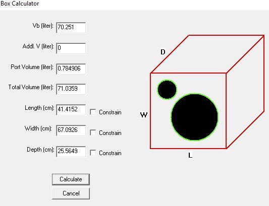
ECE 40020                     Sound Reinforcement System Design                      Spring 2018

        The following are the woofer’s relevant small signal parameters. These parameters were
taken into account throughout our design process:
    ● Qts: .33                                           ● Vd: .366 l,
    ● Qes: .37                                           ● Xmax: 7mm,
    ● Fs,: 24.2 Hz                                       ● Sd: 522.8 cm2
    ● Vas: 151.7                                         ● SPL: 89.6 @ 1W/1m,
    ● Pmax : 240 W,

        Now, since we chose to use a vented enclosure, we also had to choose what type of
alignment our subwoofer would use. Our choices consisted of SBB4, QB3, and SC4. We chose
to use the QB3 alignment. In addition to extending the 3dB point below that of the other
alignments, QB3 controlled cone displacement much more effectively than the other two
alignments. In fact, both the SBB4 and SC4 alignments exceeded our driver’s maximum for cone
displacement. By using design tools such as Speaker Box Lite, we were able to find minimum
port diameters. Because we did not want the port to make the subwoofer too loud, we decided to
use the minimum port diameter, which was 3”.

       Our final dimensions were about 26.5”x16.25”x10”. These dimensions are almost exactly
matched to our designs done through ajdesigner and other subwoofer design websites, which
were 26.4”x16.3”x10.0”. The dimensions calculated using Speaker Box Lite were about the
same as our calculations done on ajdesigner, which reinforced our confidence in our calculations.
Confirmed through our final measurements and comparisons with our calculations, our
subwoofer enclosure fulfills the “golden ratio” requirements. This means that the geometry of
our box should optimize the sound it creates.

       We also needed to find several characteristics of our subwoofer. These included features
such as box resonance, volume, and power frequency. By inputting specifications of our
subwoofer into ajdesigner, we determined several parameters for our loudspeaker. The box
volume came out to be 70.3 liters, the box resonance was 29.1 Hz, the -3 dB half power
frequency was 33.48 Hz, and the port length was about 17.3 cm. These numbers were also
confirmed by Speaker Box Lite.

       From the frequency response curve predicted by ajdesigner, it was expected that the
subwoofer would begin rolling off around 50 Hz. From our measured response curve (see
appendix D), the frequency began to drop around 63 Hz. This was higher than expected, and
could have resulted in less accurate crossover frequencies. However, this shouldn’t be much of a
problem, as the general consensus of our subjective listening tests was that the system sounded a
bit “muddy” (meaning that the bass was overpowering).

                                                7
ECE 40020 Sound Reinforcement System Design Spring 2018
3.0 Results
Before assessing our results, it should be noted that we used our own custom-built
subwoofer during our testing phase and subjective listening tests. While a test subwoofer was
provided for us, we felt that since we wanted our system to be a 4-element system, it would be
better to test the system as one unit.
Across the frequency spectrum, there was a relative balance in the frequency response of
our system. However, there were certain frequencies that dropped, particularly drops in the
midrange and 2kHz. Additionally, our system did not quite satisfy the target constraint of +/-3
dB from 40 Hz to 16,000 Hz. While we were fairly close, problems with our crossover filters
were most likely the leading causes of our issues in our frequency response. Because of the
problems from our crossover filters, some drivers were powering frequencies outside of their
specified range. For example, our crossover from midrange to the tweeter was at 3 kHz.
However, the midrange driver is not capable of handling frequencies much above 2 kHz. For this
reason, the crossover frequency between these two drivers should have been much lower, likely
around 2 kHz or even 1.5 kHz. These issues with the crossover frequencies made certain
frequencies erratic and “choppy”. These problematic frequencies were made evident during our
subjective listening tests.
During our subjective listening tests, the group listened to a wide variety of music on the
system. With genres ranging from hip-hop to jazz to pop to hard rock to classical music, we
wanted to ensure that our system sounded accurate by listening to tracks with which we were
familiar. Songs used as reference tracks included:
1. “Treetop Flyer” by Stephen Stills
2. “Check the Rhime” by A Tribe Called Quest
3. “So It Goes” by Hi-Lo Jack
4. “Make a Change” by Durand Jones & the Indications
5. “O Fortuna” by Carl Orff
6. “Dat Dere” by Art Blakey and the Jazz Messengers
7. “Girlfriend” by NAO
8. “Cut Your Hair” by Pavement
9. “Norwegian Wood” by Victor Wooten
10. “When You Sleep” by My Bloody Valentine
11. “The Way You Make Me Feel” by Michael Jackson
12. “Here Comes the Sun” by The Beatles
Particularly in the low end, the texture of the sound created by our system is rather soft.
Additionally, the added power from the subwoofer gives the system a warmth that it especially
lacked before we implemented it into our system. Also, the brightness created by the original
tweeter we had is gone, and the higher frequencies are well balanced with the rest of the
frequency spectrum. The main problem we found through our subjective listening tests was a
“peakiness” in the midrange frequencies.
Through our subjective listening tests, we also found problems with vocals for certain
pop songs. Particularly in “The Way You Make Me Feel” by Michael Jackson and “Here Comes
the Sun” by The Beatles, we found that the voice often felt “masked” by the other parts of the
8ECE 40020 Sound Reinforcement System Design Spring 2018
song. With songs like these, the vocals should be sitting in front of the instruments, but the voice
was often too soft and drowned by the rest of the sounds in the songs.
Overall, the system performs fairly well. There is a relatively flat balance across the
frequency spectrum, and the subwoofer certainly adds a significant warmth and bass “thump” to
the system. However, there were some problems with uneven response in the midrange/presence
region and midbass frequency range. At some points in the frequency response (200 Hz being a
great example), significant dips in driver response call for a boost or reduction in power. At other
points, our crossover cut-offs could be shifted to better follow the tendencies of the Had we had
more time, we would likely work more on our crossover filters and tuning the system.
9ECE 40020 Sound Reinforcement System Design Spring 2018
4.0 References
Raymond, J. (n.d.). AJ Design Software. Retrieved April 05, 2018, from
https://www.ajdesigner.com/
Free subwoofer box calculator online. (n.d.). Retrieved April 05, 2018, from
https://speakerboxlite.com/
(n.d). Parts Express. Retrieved April 05, 2018, from https://www.parts-express.com/resources-
crossover-faqs/
"Dayton Audio SD315A-88 12" DVC Subwoofer" Product. (n.d.). Retrieved April 05, 2018,
from https://www.parts-express.com/dayton-audio-sd315a-88-12-dvc-subwoofer--295-
488#lblProductDetails
10ECE 40020 Sound Reinforcement System Design Spring 2018
Appendix A:
Activity Logs
Activity Log for: Tae Hyun Kim (Frank) Role:
Time
Activity Date Start Time End Time
Spent
Discussed about doing analog design over 03/01 09:00 10:30 1.5hr
using DSP development board for the
crossover. Also briefly talked about planning
for the designing analog crossover design.
Researching about designs of crossover 03/06 09:00 10:30 1.5hr
Spent time on a crossover filter design and 03/10 12:30 13:30 1Hr
meet with professor Meyer about some
technical related questions.
Started working on a crossover filter design 03/14 12:30 15:30 3Hr
Continued working on a crossover design 03/18 12:30 15:30 3Hr
Reviewed materials for exam 2 03/28 20:00 3:00 7Hr
Picked up the MDF enclosure 04/02 16:00 16:30 0.5Hr
Finished designing crossover design 04/04 21:30 23:00 2.5Hr
Finished testing the crossover design 04/05 1:00 2:00 2Hr
11ECE 40020 Sound Reinforcement System Design Spring 2018
12ECE 40020 Sound Reinforcement System Design Spring 2018
Activity Log for: Joe Coleman Role:
Time
Activity Date Start Time End Time
Spent
Discussed and researched enclosures for the 03/19 8:00 PM 10:00 2 hr
subwoofer. Ended up deciding on a ported
subwoofer enclosure.
More subwoofer design discussion and 3/24 8:30 PM 10:00 1.5 hr
planning
Discussed analog crossover design 4/2 8:30 PM 9:30 1 hr
Corrected cuts on subwoofer enclosure and 4/3 10:15 AM 11:15 1 hr
planned construction of subwoofer.
Bought materials needed for construction of 4/3 2:30 PM 3;15 .75 hr
subwoofer
Constructed subwoofer 4/3 6:15 AM 9:15 3 hr
Helped design, construct, test, and refined 4/4 6:00 PM 4:00 AM 10 hr
final analog crossover filter.
13ECE 40020 Sound Reinforcement System Design Spring 2018
Activity Log for: AJ Trent Role:
Time
Activity Date Start Time End Time
Spent
Researched Subwoofer Drivers 03/08 14:30 15:30 1 hr
Researched sub drivers/preliminary design 03/19 14:30 15:30 1 hr
Worked on sub design/ordered parts 03/19 17:00 19:00 2 hr
Discussed sub design, did some calculations 03/24 20:30 22:00 1.5 hr
and decided on more details of the design
Finalized and double checked calculations of 03/27 21:00 23:00 2 hr
volume (+dimensions), port size/length, and
ordered a port from Parts Express.
Constructed Subwoofer 4/3 19:00 00:30 5.5 hr
Tested System, Wrote Report, and finalized 4/4 21:00 04:30 7.5 hr
Crossovers
14ECE 40020 Sound Reinforcement System Design Spring 2018
15ECE 40020 Sound Reinforcement System Design Spring 2018
Activity Log for: Oscar Otero Role:
Time
Activity Date Start Time End Time
Spent
Worked on sub design/ordered parts 03/19 17:00 19:00 2 hr
Discussed sub design, did some calculations 03/24 20:30 22:00 1.5 hr
and decided on more details of the design
Finalized and double checked calculations of 03/27 21:00 23:00 2 hr
volume (+dimensions), port size/length, and
ordered a port from Parts Express.
Corrected Subwoofer Cuts and Planned 4/3 10:15 11:15 1 hr
Construction
Constructed Subwoofer 4/3 19:00 00:30 5.5 hr
Tested System, Wrote Report, and finalized 4/4 21:00 4:30 7:30
Crossovers
16ECE 40020 Sound Reinforcement System Design Spring 2018
Appendix B:
(DSP) System Tuning Parameters
17ECE 40020 Sound Reinforcement System Design Spring 2018
Include schematic (with optional PCB layout) for analog spectral divider design -or- system
tuning parameters (screen shots or photos) for DSP design.
Appendix C:
Frequency Response
Measurement
18ECE 40020 Sound Reinforcement System Design Spring 2018
Include frequency photos of test setup and spectrum analyzer output here. Make sure that the
“scale” settings are clearly visible.
Total Frequency Spectrum:
Subwoofer:
Woofer:
Squawker::
Tweeter:
19ECE 40020 Sound Reinforcement System Design Spring 2018
Photos of AJ Critically Listening
20ECE 40020 Sound Reinforcement System Design Spring 2018
Appendix D:
Subwoofer Design Documentation
(optional – bonus credit)
21ECE 40020 Sound Reinforcement System Design Spring 2018
22ECE 40020 Sound Reinforcement System Design Spring 2018
23You can also read


