Large strain hardening of magnesium containing in situ nanoparticles
←
→
Page content transcription
If your browser does not render page correctly, please read the page content below
Nanotechnology Reviews 2021; 10: 1018–1030
Research Article
Zhongxue Feng, Yuhua Zhang, Jun Tan*, Yuming Chen, Yiming Chen, Jianbo Li, Xianhua Chen,
Kaihong Zheng, and Fusheng Pan
Large strain hardening of magnesium containing
in situ nanoparticles
https://doi.org/10.1515/ntrev-2021-0074
received May 18, 2021; accepted August 21, 2021
Abstract: In this work, in situ magnesium-based compo-
site composed of nanoscale magnesium oxide (MgO),
prepared by spark plasma sintering, shows significant
plasticity and high strain hardening. During the strain-
hardening stage, the incremental work-hardening expo-
nent shows drastic fluctuations due to the pile-up and Graphical abstract
release of dislocations. The dislocation pile-up at the
interface makes it possible to form dislocation cells.
Mixed dislocations can be generated within the cells sur- Keywords: nanoparticle, magnesium oxide, spark plasma
rounding the MgO particles, which can interact with the sintering, work hardening, fracture behavior
stress field and effectively hinder the movement of dis-
locations, leading to an increase in dislocation density.
What is more, grain boundaries have higher elastic mod-
ulus and hardness, which may lead to the appearance of 1 Introduction
microcracks and eventually intergranular fractures. Our
results may shed some light on understanding the role of In general, the phenomenon of strain hardening (or work
MgO particles in influencing the mechanical properties of hardening) refers to the increase in strength and hardness of
Mg alloys and Mg-based composites, especially in work a material during plastic deformation below the recrystalli-
hardening. zation temperature (e.g., room temperature), preventing
further deformation of the material [1]. On the one hand,
strain hardening can cause further machining difficulties for
metal parts. However, its strain hardening can be eliminated
* Corresponding author: Jun Tan, National Engineering Research by an intermediate annealing process [2]. On the other hand,
Center for Magnesium Alloys, Chongqing University, Chongqing it improves the strength [3,4], hardness [5,6], and wear resis-
400044, China; College of Materials Science and Engineering,
tance [7,8] of metals, which is particularly important for
Chongqing University, Chongqing 400044, China,
e-mail: tanjuncn@gmail.com, jun.tan@cqu.edu.cn
pure metals and certain alloys that cannot be strengthened
Zhongxue Feng: Faculty of Materials Science and Engineering, by heat treatment [9]. Therefore, strain hardening can
Kunming University of Science and Technology, Kunming 650093, hinder the continued development of plastic deformation
China; National Engineering Research Center for Magnesium Alloys, and greatly improve the safety of the components.
Chongqing University, Chongqing 400044, China Magnesium (Mg) alloys and their composites are
Yuhua Zhang, Yuming Chen: Faculty of Materials Science and
being actively developed and used in many applications,
Engineering, Kunming University of Science and Technology,
Kunming 650093, China including the automobile, aircraft, and aerospace indus-
Yiming Chen: College of Materials Science and Engineering, tries, because of their potential to improve energy effi-
Chongqing University, Chongqing 400044, China ciency [10–12]. However, the limited strength and stiffness
Jianbo Li, Xianhua Chen, Fusheng Pan: National Engineering of Mg alloys have restricted their large-scale application as
Research Center for Magnesium Alloys, Chongqing University,
structural materials [13–16]. As a result, Mg-based compo-
Chongqing 400044, China; College of Materials Science and
Engineering, Chongqing University, Chongqing 400044, China
sites have been developed to improve the engineering
Kaihong Zheng: Institute of New Materials, Guangdong Academy of strength and elastic modulus by adding reinforcements
Sciences, Guangzhou 510650, China such as MgO [17], Al2O3 [18–20], SiC [21], TiC [22,23],
Open Access. © 2021 Zhongxue Feng et al., published by De Gruyter. This work is licensed under the Creative Commons Attribution 4.0
International License.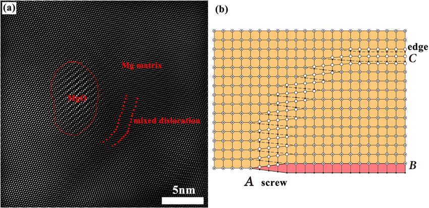
Large strain hardening of magnesium containing in situ nanoparticles 1019
TiO2 [24], and CNTs [25–27]. Among them, MgO is almost small satellites around the larger particles as shown in
inevitable in the preparation and processing of Mg alloys Figures 1a and b. One can see that in Figure 1c and d, the
and Mg-based composites, although they are prepared in particle sizes vary from 20 to 130 µm, and 90% of the Mg
protective gas or even low vacuum. The excellent mechan- powder size is smaller than 94.0 ± 0.5 µm (D90, corre-
ical, physical, and thermal properties of MgO have been sponding to 90% of the particle size of the cumulative
reported to make it a good candidate for the reinforcement size distribution of the sample, i.e., 90% of the particles
of Mg-based composites [28]. are smaller than it). The median size (D50) is about 60.5 ±
Plastic deformation of materials containing hard nano- 0.5 µm. The value of D10 is 36.6 ± 0.5 µm. The particles of
particles generates internal stresses proportional to the different sizes were intentionally chosen in the hope of
applied plastic strain, which must be exceeded before obtaining high densification during the sintering process.
further deformation can occur [29]. Then, strain hardening The size distribution is also fitted by Gaussian function,
may occur due to dislocation movement and dislocation and the mean value of the particle size is 67.7 ± 0.9 µm
generation in the crystal structure of the material [30]. In with a high coefficient of determination (COD, R2) of 96.3%.
a simple tension (uniaxial tensile test), strain hardening
means only that the stress is a monotonically increasing
function of the strain. The plastic deformation is then said 2.2 SPS preparation
to be stable [31]. The different weight percentages of Al2O3
nanoparticles in pure Mg and AZ31 affect the work-hard- Mg powder was pre-pressed into a graphite mold (10 mm
ening behavior. The work-hardening capacity (WHC) diameter) at a pressure of 15 MPa. It was then sintered
varies from 0.05 to 1.07 [20]. It has also been reported with SPS at 853 K under argon (99.99%) atmosphere at a
that there was no significant strain hardening in the pressure of 35 MPa for 15 min.
MgO/Mg composites prepared by disintegrated melt
deposition method coupled with hot extrusion [32].
However, the distribution characteristics of MgO and 2.3 Characterizations
the influence of the interface between MgO and Mg
matrix on the mechanical behaviors, such as strain The samples were machined, polished, and characterized
hardening and fracture behavior, are still elusive. to determine their microstructure and mechanical pro-
In the present study, in situ MgO/Mg composite is perties. The microstructure was investigated using scan-
prepared by spark plasma sintering, and the mechanism ning electron microscopy (SEM) and energy dispersive
of MgO influence on the mechanical properties and frac- spectroscopy (EDS) techniques. Transmission electron
ture behavior of the Mg matrix will be investigated in microscopy (TEM) was also used to investigate the micro-
detail. Our results may be enlightening for understanding structure of the matrix and the interface between the
the role of MgO particles in influencing the mechanical Mg matrix and the MgO particles. Moreover, SEM and
properties of Mg alloys and Mg-based composites. TEM were also used to analyze tensile fractography and
failure behaviors. The elastic modulus and hardness were
conducted by nano-indentation under the Nano-Blitz
2 Experimental details 3D mode at a constant force of 10 mN. The holding time
was 1 s, the test was performed at a 30 × 30 array, and
2.1 Materials the interval between each adjacent test point was 5 µm
to avoid mutual interference. Tensile tests were per-
formed on specimens of 9 mm gauge, 2 mm width, and
Mg powder with a purity of 99.8% was used for spark
1 mm thickness at a strain rate of 1 × 10⁻³ s–1 at room
plasma sintering (SPS). The composition of the raw mate-
temperature.
rial is listed in Table 1. One can see that the Mg powder
contains a small amount of Fe, Zn, and C. Figure 1 shows
the morphology and powder size distribution of the Mg
powder. All Mg particles are almost round with many 3 Results
Table 1: Chemical composition of Mg powders
3.1 Microstructures
Elements Mg Fe Zn C
Samples with a diameter of 10 mm and a height of about
Concentration (wt%) 99.81 0.008 0.008 0.004
20 mm were successfully sintered by SPS. SEM and TEM
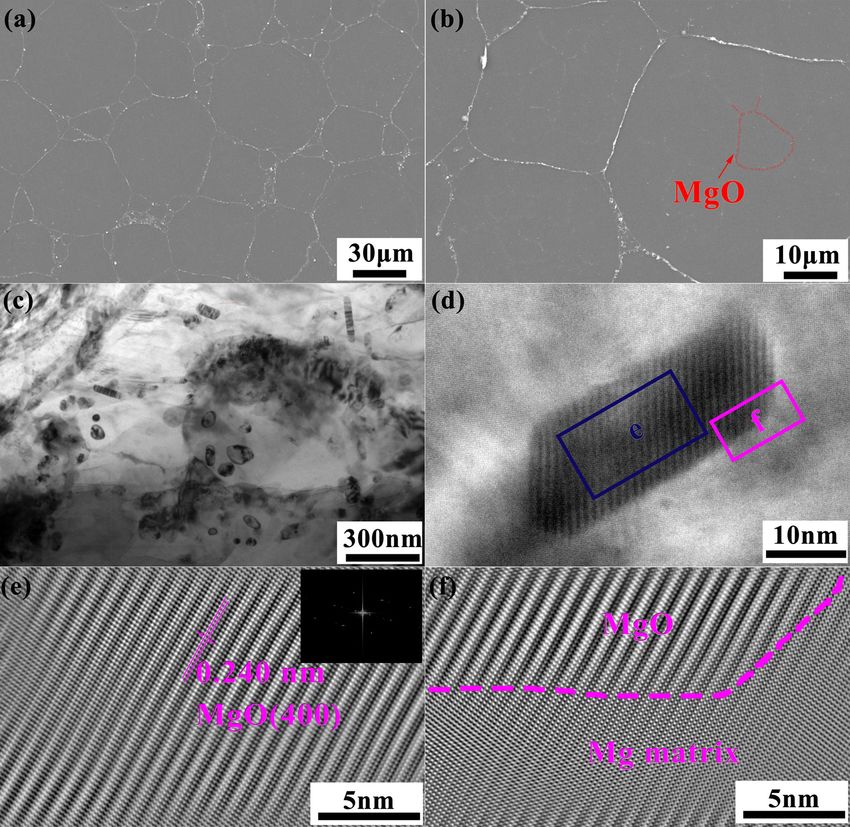
1020 Zhongxue Feng et al. Figure 1: The morphology and the size distribution of Mg powders. (a) The macroscopic morphology of the particles. (b) An enlargement view of the particles showing that Mg particles are almost round with many small satellites around the larger particles. (c) The size distribution of Mg powders. The blue curve is fitted by Gaussian function and the corresponding mean value and standard error are shown in the inset. (d) The cumulative size percentage as a function of particle size. were used to investigate the microstructure and the dis- unlike the MgO in the melt, which relies only on the tribution of MgO (Figure 2). As can be seen in Figure 2a, a interface energy and forms a completely spherical shape. large number of fine MgO particles are concentrated near Figure 2d shows a high-resolution image of a MgO par- the particle boundaries. Figure 2b shows a magnified ticle, and Figure 2e shows the inverse fast Fourier trans- view. One can see that a very small amount of MgO form (IFFT) of the region marked with a blue rectangle in particles is retained within the original Mg powder, as Figure 2d (marked with a blue “e”). According to the exemplified by some areas marked with red dotted lines. atomic stacking characteristics of MgO, we can distinguish Moreover, the morphology of MgO particles near the the interface between MgO and matrix. As shown in Figure grain boundaries was observed by TEM, illustrated in 2f, it has good interfacial adhesion between MgO and Figure 2c. Several different shapes can be observed, like Mg matrix. Therefore, the in situ MgO/Mg composite is sphericity, rod, and irregular shape. It is believed that expected to obtain excellent mechanical properties. there are two possible sources of MgO in this work. The content and distribution of the MgO particle are First, due to the chemical active nature of Mg, many of great importance to the mechanical properties of the MgO particles will inevitably be produced on the surface MgO/Mg composite. First of all, the high-resolution SEM of powder during the powder preparation process. On the images were converted to black and white mode using other hand, residual oxygen diffuses to form MgO parti- open-source Python and OpenCV, which is a library of cles despite the short sintering time of about 15 min Python bindings designed to solve computer vision pro- required by the SPS process and the low vacuum envir- blems. The size distribution was then counted and shown onment. Since the nuclear of MgO depends mainly on the in Figure 3. One can see that most sizes of MgO particles shape of the interface defects between the powders in are of the order of a nanometer, ranging from several SPS, the MgO shows various shapes in the Mg matrix, nanometers to ∼250 nm. The percentage of the sizes

Large strain hardening of magnesium containing in situ nanoparticles 1021
Figure 2: Microstructure of the as-sintered specimen. (a) SEM image of MgO/Mg composite prepared by spark plasma sintering. (b) A small
amount of MgO particles were kept inside original Mg powders, marked with red dotted lines. (c) The morphology of MgO particles near the
particle boundaries is sphericity, rod, and irregular shape. (d) High-resolution TEM image of the interface between MgO and Mg matrix.
(e) An inverse fast Fourier transformation (IFFT) of the area marked with blue rectangle labeled with blue e in (d) and the inset shows the
corresponding diffraction pattern. (f) An IFFT of the area marked with pink rectangle labeled with pink f in (d) indicating a good interfacial
adhesion between MgO and Mg matrix.
below 17 nm is 25.5%. The average particle size was about
22 ± 1 nm. The content of the MgO was 0.52 ± 0.08%
calculated based on the area of the MgO particles.
3.2 The elastic modulus and hardness
Nanoindentation was used to investigate the elastic mod-
ulus and hardness around the interface of the Mg matrix
in the Nano-Blitz 3D mode, which continuously measures
the force and displacement over the entire area around
the interface in constant steps (5 μm), making it possible
to observe the evolution of the mechanical properties
between the interface and the matrix (Figure 4). The rela-
tionship between the elastic modulus (E) and the inden-
Figure 3: The size distribution of MgO particles in composite. tation depth (h) can be described as follows [33]:
1022 Zhongxue Feng et al.
Figure 4: Three-dimensional graph and the corresponding contour map of the (a) elastic modulus and (b) hardness distribution of the
specimen with an area of 150 µm × 150 µm.
π dP 11 ± 1%, respectively. Based on the engineering stress–
E= , (1)
2 A dh strain curve, the true stress–strain curve can be calcu-
where E represents the elastic modulus and A represents lated as shown in Figure 5b.
the project area of the contact surface between the indenter To further analyze the evolution of the mechanical
and the matrix after the nanoindentation test. In the properties, the curve can be divided into three stages:
Berkovich triangular pyramid indenter, A = 24.56hc2 where elastic stage I, first strain-hardening stage II, and second
hc represents the vertical depth of the contact surface and strain-hardening stage III. This material exhibits a pro-
dP / dh represents the slope of the highest point of the nounced yield stage, which is different from other
unloading curve [34]. Mg-based composites, and it may be related to the dis-
In Figure 4, a 3D plot of the elastic modulus and location pile-up at the interface. One can see that the
hardness of a sintered sample containing several Mg par- yield strength (YS) and ultimate tensile strength (UTS)
ticles is shown. Significant changes of the elastic mod- are 70 ± 2 and 170 ± 2 MPa, respectively. To our surprise,
ulus and hardness are observed at the interface. The large strain hardening occurred in all replicate tests of
elastic modulus and hardness of the interface are higher in situ MgO/Mg composite prepared by SPS. However,
than those of the Mg matrix, and the maximum values ex-situ 1.0 vol% MgO/Mg composites prepared by the
can reach 42 and 1.6 GPa, respectively. The average disintegrated melt deposition method coupled with
elastic modulus and hardness of the Mg matrix are only hot extrusion had no significant strain-hardening stage
27 and 0.85 GPa. Fortunately, the mechanical properties investigated by Goh et al. [32]. The work-hardening capa-
are continuous in the transition region between the inter- city (WHC), defined as (UTS–YS)/YS, can be as high as
face and the matrix, which indicates that the bonding 1.43, which is much higher than that of Mg-based com-
force is sufficient to improve the mechanical properties posites reinforced by Al2O3, SiC, TiB2, graphene nano-
of the whole composite, which also suggests that there platelets, graphene oxide, and so on [18–20,36–41].
are no obvious defects between the MgO particles and the
Mg matrix. And unlike the loose structure of the oxide
layer in casting [35], in this work, by SPS, it has a good
coherent interface between the MgO and the Mg matrix. 4 Discussion
4.1 Strengthening mechanisms of the
3.3 Tensile testing composite
The tensile engineering stress–strain curve of the MgO/Mg Nanoparticles can improve the yield strength of the
composite prepared by SPS is shown in Figure 5a. The matrix of a composite [42,43]. The yield strength (σy) of
tensile strength and elongation of Mg are 156 ± 2 MPa and our in situ MgO/Mg composite is associated with the
Large strain hardening of magnesium containing in situ nanoparticles 1023
Figure 5: Tensile mechanical properties of the specimen at room temperature. (a) Engineering stress–strain curve and (b) true stress–strain
curve of the specimen, which can be divided into three stages: elastic stage I, yield stage II, and strain-hardening stage III. (c) Strain-
hardening exponent in different deformation stages. (d) Incremental-hardening exponent nincr as a function of the natural logarithm of true
strain ln(εT).
Hall–Petch effect [44,45], the Orowan strengthening applied stress to generate dislocations in the adjacent
mechanism (ΔσOrowan) [46], and the modulus mismatch grains [49,50]. During uniaxial tensile loading, MgO/Mg
mechanism (ΔσModulus) [47]. Therefore, the quadratic composites without following hot or cold deformation,
summation method can be used to predict the yield like rolling and extrusion, have low friction stresses
strength [48]: when dislocations slip on the slip plane [51].
Grain size has a profound effect on the value of k
σy = σ0 + k / d 1 / 2 + (ΔσOrowan 2 + ΔσModulus 2 )1 / 2 , (2)
because it controls the original stress concentration gene-
where σ0 is the friction stress when the dislocations slide rated by dislocation pile-up [52], and hence, the length of
on the slip plane, k is the stress concentration factor, and the dislocation acts on the dislocation sources in the
d is the size of the Mg matrix. The yield stress increases adjacent grains [49]. Hence, σ0 and k are set as 8.5 and
with decreasing d because pile-ups in the fine-grained 294 MPa µm1/2, respectively [53], and the value of d can
material contain fewer dislocations, the stress at the tip be obtained approximately from the Gaussian fitting
of the pile-up decreases and, thus requiring a larger parameter (67.7 µm) in Figure 1c. So, the contribution of
1024 Zhongxue Feng et al.
the grain refinement strengthening (Hall–Petch strength- presence of MgO nanoparticle reinforcement, many geo-
ening) is up to 44.2 MPa. metrically necessary dislocations must be generated to
MgO particles hinder dislocation motion and leave a accommodate the moduli difference between the matrix
dislocation loop around them [54]; thus, the Orowan and the particles. Therefore, this modulus strengthening
strengthening needs to be considered and ΔσOrowan can must be applied to the composite during tensile loading,
be roughly described by the Orowan–Ashby equation [46]: and the strength improvement resulting from the mod-
ulus mismatch (ΔσModulus) can be calculated by ref. [48]
0.13Gmb dp
ΔσOrowan = ln⎛ ⎞ ,
⎜ ⎟
1/3 2b (3) ΔσModulus = 3αGm 2VPεb/ dP , (4)
dp⎡
⎢
⎣
( )1
2Vp
− 1⎤ ⎝ ⎠
⎥
⎦ where α is the material-specific coefficient, which is 0.5
where Gm is the shear modulus of the Mg matrix, b is the for mixed dislocations [47]. ε is the strain of the compo-
Burgers vector, dp is the size of the MgO particles, and Vp site, which is 0.2% for yield. So, the contribution of the
is the volume percentage of the reinforcement. The fol- modulus mismatch strengthen can only reach 12.2 MPa.
lowing values were used to estimate the Orowan strength However, the modulus mismatch strengthen can be further
of the composite: Gm = 16.9 GPa [55] and b = 0.32 nm [32]. enhanced with increasing strain [56].
The value of the ΔσOrowan can be plotted according to Consequently, the yield strength can be calculated
different Vp and dp, as shown in Figure 6. Therefore, by the quadratic summation method with a value of
one would expect an increase in ΔσOrowan for a higher approximately 78.0 MPa, which is consistent with the
volume percentage of the MgO particles (Vp) and smaller yield strength value of 70 ± 2 MPa for the true stress–true
size of MgO particles (dp). In this case, we set dp = 22 nm stress curve. If the arithmetic summation method is used,
and Vp = 0.52% based on the average of the statistical which simply sums the contribution of the individual
data in Figure 3. The contribution of the Orowan strength- strengthening mechanisms in a linear fashion, the yield
ening can reach 31.6 MPa. strength value is 88.0 MPa, which is slightly higher than
In addition to grain refinement and Orowan mechan- that from the true stress–true stress curve, Therefore, the
isms, the modulus mismatch strengthening mechanism small size of the matrix, and high vol% of the reinforce-
can also improve the strength of composites. The mod- ment with small size favor higher yield strength for in situ
ulus mismatch strengthening mechanism describes the MgO/Mg composite. It is noted that the size contribution
generation of geometrically necessary dislocations when of a matrix (Hall–Petch strengthening) is dominant in
a composite is subjected to tensile loading. Because of the this work.
Figure 6: The Orowan strength as functions of (a) volume percentage (Vp) and (b) grain size (dp) of reinforcement, respectively, implying a
high Orowan strength lies in high vol% of the MgO particles and small grain size of MgO particles.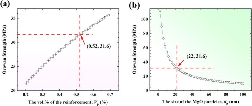
Large strain hardening of magnesium containing in situ nanoparticles 1025
4.2 Origin of the strain hardening • external loads and constraints,
• internal stress fields,
The strain-hardening coefficient (or work-hardening index, n) • or higher or lower compliance interaction interfaces.
can be obtained by fitting the uniaxial tensile curve with
Holloman’s equation and further quantifying the work- In the tensile test of in situ MgO/Mg composite, the
hardening effect. The Holloman’s equation is a power–law external loads come from the applied stress at both ends
relationship between the stress and the plastic strain and of the specimen. In addition, these stresses generate
can be expressed as follows [57]: shear stresses at the level of the slip plane. In the disloca-
tion theory of plasticity, the relation between the shear
σT = kεTn, (5)
stress (τ) and the dislocation density (ρ) during the uni-
where k is the strength coefficient. The value of n is axial tensile test can be expressed as
between 0 and 1. n = 0 means that the material is a perfect
τ = αGmbρ1 / 2 , (7)
plastic solid; while n = 1 represents a 100% elastic solid.
Figure 5c shows the strain-hardening coefficient in dif- where α is a constant at room temperature, Gm is the
ferent stage. Stage I is the elastic stage, so n = 1 (not shear modulus of the Mg matrix, and b is the Burgers
shown here), stage II is the first strain-hardening stage vector. Therefore, the ratio of the dislocation density is
and it is a transition of elastic deformation to elastic-plastic equal to the square ratio of the corresponding applied
deformation stage with a strain-hardening coefficient of stress.
∼0.16, and stage III is the second strain-hardening stage Internal stress fields can be generated by the micro-
with n = 0.61, which is larger than the coefficient of the structural features/influences of the MgO particles. These
previous stage. It can be concluded that in stage III, the stresses can lead to certain shear stresses on the slip
homogeneous deformability increases with increasing plane.
strain [58]. Most metals have n values between 0.10 and What’s more, because of the different modulus
0.50, i.e., the value of 0.61 exceeds that of most metals between the Mg matrix and MgO particles, the interaction
[59], e.g., 4340 steel (tempered at 315°C, 0.12), AZ31B of the internal stress field with the interfaces can lead
magnesium alloy (annealed, 0.16), 2024 aluminum alloy to the difference of the inherent stress field. There are
(T3 heat treatment, 0.17), low-carbon steel (annealed, 0.21), three possible routines for the evolution of the disloca-
naval brass (annealed, 0.21), 304 stainless steel (annealed, tions [61]:
0.44), copper (annealed, 0.44), and transformation-induced • A free surface will attract dislocations.
work-hardening ZrCo alloy (0.51) [5]. • When a moving dislocation slides over a soft coherent
Figure 5d presents the variation of the incremental obstacle with a lower modulus, it will shear it. However,
work-hardening exponent (nincr) as a function of the nat- in our case, MgO particles are harder than the Mg matrix,
ural logarithm of true strain, i.e., ln(εT), given by ref. [60]: so this is not possible.
d ln σT • A dislocation can be pinned, thus hindering the dislo-
nincr = . (6) cation motion. So, the dislocation has to bypass the
d ln εT
pinned part under the applied stress. This leads to an
It is well known that the large homogeneous defor- increase in dislocation density.
mation of specimens is associated with a high, and
slightly increasing nincr during plastic deformation [60]. To further explore the strain-hardening mechanism,
In our specimen, however, the value of nincr fluctuates in the microstructure near the tensile fracture region was
the range of −20 to 20 and its amplitude is increasing with investigated by TEM. As shown in Figure 7, MgO parti-
increasing strain until fracture, showing a trumpet-like cles, which gathered at the grain boundaries, could pin
shape. In comparison with other Mg-based composites, the dislocations, causing the dislocation lines to accumu-
this specimen presents a completely different evolution late near the grain boundaries, and forming dislocation
of work hardening during plastic deformation. May it cells (Figure 7a). The cell walls exhibit a loose structure
associate with the pile-ups and release behavior of with thickness ranging from tens to hundreds of nan-
dislocations? ometers. After deducting the dislocation wall thickness,
Local shear stresses are necessary for the slip of dis- the inner width of the cell in our TEM image is estimated
locations. The density of dislocations will increase origin- to be 720 nm and the dislocation cell concentrates at the
ally from the increasing local shear stresses, arising from grain boundaries. Due to the high density of the MgO
three possible sources [61]: particles around the grain boundaries, the glide of
1026 Zhongxue Feng et al.
Figure 7: TEM images of the (a) dislocation cell and (b) dislocation glide steps in Mg sample. (c) A magnification view of the microstructure
of the dislocation cell labeled with orange c in (a). (d) The corresponding diffraction pattern in (c).
dislocations through the climb and/or cross slip would be movement of dislocation and leading to an increase in
retarded or hampered (dislocation pile-ups) and nincr dislocation density.
would increase until new dislocations are restarted or
pre-existing dislocation glide is accelerated. Then, dislo-
cations will pile-up – release – pile-up – release. Finally,
4.3 Failure behaviors of the in situ MgO/Mg
the dislocation glide steps will be formed and nincr will be
composite
increased. The dislocation glide steps, marked with a red
arrow, were observed and shown in Figure 7b. This shows
To further investigate the failure behaviors of the com-
that the dislocations are released at the interface. These
posite, the fracture morphology after tensile testing at
dislocation behaviors may be responsible for the fluctua-
room temperature was observed by SEM, as illustrated
tion of the increment strain-hardening exponent in in situ
in Figure 9a. The micro-fracture surface was character-
MgO/Mg composite prepared by SPS. The microstructure
ized as “rock sugar,” consisting of sharp edges and cor-
of the inner dislocation cell is displayed in Figure 7c.
ners with a strong polyhedral feel, representing a typical
Many stacking faults are formed within the cell. To ana-
intergranular fracture. In addition, many microcracks
lyze whether the twining has occurred during the plastic (marked by red arrows) can be found around the particle
deformation process, electron diffraction of the area d boundaries. In the present work, the microcracks start at
was tested [58]. The selected area diffraction pattern the same position as the peak of the elastic modulus
(SADP) is shown in Figure 7d, indicating the absence of (Figure 9b). The reason can be explained as follows.
twining within the dislocation walls. The relationship between the volume strain (θ ) and
The type of dislocation within the dislocation walls stress can be determined by the following formula:
was distinguished by high-resolution TEM, as shown in
3(1 − 2μ) σ1 + σ2 + σ3
Figure 8a. By comparing with the atomic model of the θ= , (8)
mixed dislocation shown in Figure 8b, the dislocation E 3
can be considered as a typical mixed dislocation located where μ denotes the Poisson’s ratio, E is the elastic mod-
around the MgO particle. The interface is marked with red ulus, σ1 , σ2 , and σ3 are three principal stresses, respec-
σ +σ +σ
dots in Figure 8a. It is further verified that MgO can tively. If σm = 1 32 3 , equation (8) can be transformed
interact with the stress field, effectively hindering the into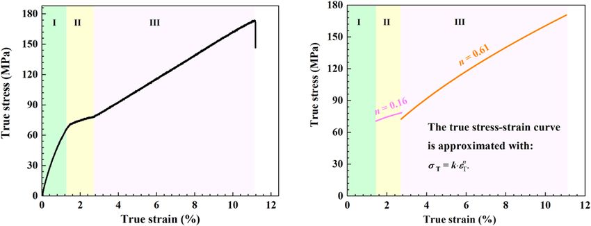
Large strain hardening of magnesium containing in situ nanoparticles 1027
Figure 8: The interaction between dislocations and MgO particle. (a) A high resolution TEM IFFT image of mixed dislocation near MgO
particle and (b) a atomic model of mixed dislocation.
Figure 9: (a) Fracture morphology after tensile testing at room temperature and (b) the contour map of elastic modulus indicating that cracks
originate at grain boundaries with higher elastic modulus marked with red arrows.
3(1 − 2μ) mismatch will increase considering the small variation
θ= σm, (9)
E of Poisson’s ratio and elastic modulus of the matrix and
where μ1 and μ2 represent the Poisson’s ratios of the reinforcement. As the grain boundaries contain a high
matrix and the reinforcement, respectively. Under the density of misfit dislocations, it will produce microcracks,
same σm , the difference in the volume strains can be leading to stress concentration and eventually intergra-
expressed by nular fracture during deformation.
3(1 − 2μ1) 3(1 − 2μ2 ) ⎤
Δθ = ⎡ − σ . (10)
⎢ E m Ep ⎥ m
⎣ ⎦ 5 Conclusion
Since the elastic modulus of the grain boundaries is
much higher than that of the Mg matrix, the volume In conclusion, in situ Mg-based composite composed of
strain difference generated by the elastic modulus magnesium oxide (MgO) as reinforcement can be1028 Zhongxue Feng et al.
prepared by using spark plasma sintering techniques. uniform dispersion of nanoparticles. Nature.
The results and discussion above allow the following 2015;528(7583):539–43.
conclusions: [2] Zhang Y, Jiang X, Sun H, Shao Z. Effect of annealing heat
treatment on microstructure and mechanical properties of
(1) These MgO particles aggregated around grain bound-
nonequiatomic CoCrFeNiMo medium-entropy alloys prepared
aries can enhance strain hardening. These distribu- by hot isostatic pressing. Nanotechnol Rev. 2020;9(1):580–95.
tion characteristics lead to the pile-up of dislocations [3] Xu T, Yang Y, Peng X, Song J, Pan F. Overview of advancement
near the interface. and development trend on magnesium alloy. J Magnes Alloy.
(2) A high strain-hardening coefficient (n = 0.61) can be 2019;7(3):536–44.
[4] Wu G, Wang C, Sun M, Ding W. Recent developments and
obtained in a uniaxial tensile test, indicating an
applications on high-performance cast magnesium rare-earth
increase in uniform deformability with increasing alloys. J Magnes Alloy. 2021;9(1):1–20.
strain. The n value of 0.61 exceeds that of most [5] Li CJ, Tan J, Wang G, Bednarčík J, Zhu XK, Zhang Y, et al.
metals. Enhanced strength and transformation-induced plasticity in
(3) MgO particles can interact with the stress field, effec- rapidly solidified Zr–Co–(Al) alloys. Scripta Mater.
2013;68(11):897–900.
tively hindering the dislocation movement and leading
[6] Chai Y, Song Y, Jiang B, Fu J, Jiang Z, Yang Q, et al. Comparison
to an increase in dislocation density.
of microstructures and mechanical properties of composite
(4) Considering the different values of elastic modulus extruded AZ31 sheets. J Magnes Alloy. 2019;7(4):545–54.
between the interface and the matrix, it suggested [7] Kocks UF, Mecking H. Physics and phenomenology of strain
that the interface may be a resource for cracks and hardening: the FCC case. Prog Mater Sci. 2003;48(3):171–273.
eventually they lead to intergranular fractures. [8] Carlton CE, Ferreira PJ. What is behind the inverse Hall-Petch
effect in nanocrystalline materials? Acta Mater.
2007;55(11):3749–56.
[9] Kong L, Zhou Y, Song K, Hui D, Hu H, Guo B, et al. Effect of
Funding information: This work was supported by the Fund aging on properties and nanoscale precipitates of Cu-Ag-Cr
for Guangdong Major Project of Basic and Applied Basic alloy. Nanotechnol Rev. 2020;9(1):70–8.
Research (Grant No. 2020B0301030006), the Fundamental [10] Xu W, Birbilis N, Sha G, Wang Y, Daniels JE, Xiao Y, et al.
Research Funds for the Central Universities (2021CDJQY- A high-specific-strength and corrosion-resistant magnesium
alloy. Nat Mater. 2015;14(12):1229–35.
040), Chongqing Special Project of Science and Technology
[11] Bommala VK, Krishna MG, Rao CT. Magnesium matrix com-
Innovation of China (cstc2021yszx-jcyj0007), the National posites for biomedical applications: a review. J Magnes Alloy.
Natural Science Foundation of China (Grant No. 51861016), 2019;7(1):72–9.
the Scientific Research Foundation of Department of Science [12] Atrens A, Shi ZM, Mehreen SU, Johnston S, Song GL, Chen XH,
and Technology, Yunnan (Grant No. 202001AT070041), and et al. Review of Mg alloy corrosion rates. J Magnes Alloy.
2020;8(4):989–98.
the open fund from the National Engineering Research Center
[13] Yu W, Li X, Vallet M, Tian L. High temperature damping beha-
for Magnesium Alloys (KKZ6201851008) as well as Henan vior and dynamic Young’s modulus of magnesium matrix
Key Laboratory of Material Science and Technology composite reinforced by Ti2AlC MAX phase particles. Mech
(MDE2019-04). Mater. 2019;129:246–53.
[14] Hassan SF, Ho KF, Gupta M. Increasing elastic modulus,
Author contributions: All authors have accepted respon- strength and CTE of AZ91 by reinforcing pure magnesium with
elemental copper. Mater Lett. 2004;58(16):2143–6.
sibility for the entire content of this manuscript and
[15] Song J, She J, Chen D, Pan F. Latest research advances on
approved its submission. magnesium and magnesium alloys worldwide. J Magnes Alloy.
2020;8(1):1–41.
Conflict of interest: The authors state no conflict of [16] Li S, Yang X, Hou J, Du W. A review on thermal conductivity
interest. of magnesium and its alloys. J Magnes Alloy.
2020;8(1):78–90.
[17] Zhang ZY, Guo YH, Zhao YT, Chen G, Wu JL, Liu MP. Effect of
Data availability statement: The datasets generated dur- reinforcement spatial distribution on mechanical properties of
ing and/or analyzed during the current study are available MgO/ZK60 nanocomposites by powder metallurgy. Mater
from the corresponding author on reasonable request. Charact. 2019;150:229–35.
[18] Hu M, Wei S, Shi Q, Ji Z, Xu H, Wang Y. Dynamic recrystalli-
zation behavior and mechanical properties of bimodal scale
Al2O3 reinforced AZ31 composites by soild state synthesis.
J Magnes Alloy. 2020;8(3):841–8.
References [19] Chen Y, Guo Y, Gupta M, Shim V. A study of the dynamic
compressive response of AZ31/Al2O3 nanocomposites and
[1] Chen LY, Xu JQ, Choi H, Pozuelo M, Ma X, Bhowmick S, et al. the influence of nanoparticles. Int J Impact Eng.
Processing and properties of magnesium containing a dense 2016;89:114–23.Large strain hardening of magnesium containing in situ nanoparticles 1029
[20] Habibnejad-Korayem M, Mahmudi R, Poole WJ. Work hard- and mechanical properties of magnesium RZ5 alloy
ening behavior of Mg-based nano-composites strengthened based metal matrix composites. J Magnes Alloy.
by Al2O3 nano-particles. Mater Sci Eng A-Struct. 2020;8(3):780–92.
2013;567:89–94. [39] Munir K, Wen C, Li Y. Graphene nanoplatelets-reinforced
[21] Rashad M, Pan F, Guo W, Lin H, Asif M, Irfan M. Effect of magnesium metal matrix nanocomposites with superior
alumina and silicon carbide hybrid reinforcements on tensile, mechanical and corrosion performance for biomedical appli-
compressive and microhardness behavior of Mg–3Al–1Zn cations. J Magnes Alloy. 2020;8(1):269–90.
alloy. Mater Charact. 2015;106:382–9. [40] Tao J-X, Zhao M-C, Zhao Y-C, Yin D-F, Liu L, Gao C, et al.
[22] Sahoo B, Panigrahi S. Synthesis characterization and Influence of graphene oxide (GO) on microstructure and bio-
mechanical properties of in situ (TiC-TiB2) reinforced magne- degradation of ZK30-xGO composites prepared by selective
sium matrix composite. Mater Design. 2016;109:300–13. laser melting. J Magnes Alloy. 2020;8(3):952–62.
[23] Anasori B, Barsoum MW. Energy damping in magnesium alloy [41] Zhou P, Zhang S, Li M, Wang H, Cheng W, Wang L, et al. The
composites reinforced with TiC or Ti2AlC particles. Mater Sci creep behavior of Mg–9Al–1Si–1SiC composite at elevated
Eng A-Struct. 2016;653:53–62. temperature. J Magnes Alloy. 2020;8(3):944–51.
[24] Meenashisundaram GK, Nai MH, Almajid A, Gupta M. [42] Nie KB, Wang XJ, Deng KK, Hu XS, Wu K. Magnesium matrix
Development of high performance Mg–TiO2 nanocomposites composite reinforced by nanoparticles – a review. J Magnes
targeting for biomedical/structural applications. Mater Alloy. 2021;9(1):57–77.
Design. 2015;65:104–14. [43] Wu Q, Miao WS, Zhang YD, Gao HJ, Hui D. Mechanical prop-
[25] Peigney A, Garcia FL, Estournès C, Weibel A, Laurent C. erties of nanomaterials: a review. Nanotechnol Rev.
Toughening and hardening in double-walled carbon nano- 2020;9(1):259–73.
tube/nanostructured magnesia composites. Carbon. [44] Hall EO. The deformation and ageing of mild steel: III discus-
2010;48(7):1952–60. sion of results. Proc Phys Soc B. 1951;64(9):747–53.
[26] Li H, Dai X, Zhao L, Li B, Wang H, Liang C, et al. Microstructure [45] Petch NJ. The cleavage strength of polycrystals. J Iron Steel
and properties of carbon nanotubes-reinforced magnesium Inst. 1953;174:25–8.
matrix composites fabricated via novel in situ synthesis pro- [46] Zhang Z, Chen DL. Consideration of Orowan strengthening
cess. J Alloy Compd. 2019;785:146–55. effect in particulate-reinforced metal matrix nanocomposites:
[27] Rashad M, Pan F, Asif M, Li L. Enhanced ductility of a model for predicting their yield strength. Scripta Mater.
Mg–3Al–1Zn alloy reinforced with short length multi-walled 2006;54(7):1321–6.
carbon nanotubes using a powder metallurgy method. Prog [47] Dai LH, Ling Z, Bai YL. Size-dependent inelastic behavior of
Nat Sci. 2015;25(4):276–81. particle-reinforced metal–matrix composites. Compos Sci
[28] Wang Y, Fan Z, Zhou X, Thompson GE. Characterisation of Technol. 2001;61(8):1057–63.
magnesium oxide and its interface with α-Mg in Mg–Al-based [48] Kim C-S, Sohn I, Nezafati M, Ferguson JB, Schultz BF,
alloys. Phil Mag Lett. 2011;91(8):516–29. Bajestani-Gohari Z, et al. Prediction models for the yield
[29] Brown LM, Clarke DR. Work hardening due to internal stresses strength of particle-reinforced unimodal pure magnesium (Mg)
in composite materials. Acta Metall. 1975;23(7):821–30. metal matrix nanocomposites (MMNCs). J Mater Sci.
[30] Meyers MA, Mishra A, Benson DJ. Mechanical properties of 2013;48(12):4191–204.
nanocrystalline materials. Prog Mater Sci. [49] Yu H, Xin Y, Wang M, Liu Q. Hall-Petch relationship in Mg
2006;51(4):427–556. alloys: a review. J Mater Sci Technol. 2018;34(2):248–56.
[31] Drucker DC. Some implications of work hardening and ideal [50] Guan B, Xin Y, Huang X, Wu P, Liu Q. Quantitative prediction of
plasticity. Q Appl Math. 1950;7(4):411–8. texture effect on Hall–Petch slope for magnesium alloys. Acta
[32] Goh CS, Gupta M, Wei J, Lee CL. Characterization of high per- Mater. 2019;173:142–52.
formance Mg/MgO nanocomposites. J Compos Mater. [51] Grishkov V, Kopylov V, Lotkov A, Latushkina S, Baturin A,
2007;41(19):2325–35. Girsova N, et al. Effect of warm equal channel angular
[33] Sneddon IN. The relation between load and penetration in the pressing on the structure and mechanical properties of
axisymmetric Boussinesq problem for a punch of arbitrary Ti0.16Pd0.14Fe (wt%) alloy. Rev Adv Mater Sci.
profile. Int J Eng Sci. 1965;3(1):47–57. 2019;58(1):22–31.
[34] Li M, Tan J, Qin XM, Lu DH, Feng ZX, Li CJ, et al. Correlation [52] Bhaskar S, Kumar M, Patnaik A. Mechanical and Tribol-
between internal states and creep resistance in metallic glass ogical overview of ceramic particulates reinforced
thin films. J Appl Phys. 2021;129:8. aluminium alloy composites. Rev Adv Mater Sci.
[35] Karakulak E. A review: past, present and future of grain 2019;58(1):280–94.
refining of magnesium castings. J Magnes Alloy. [53] Somekawa H, Mukai T. Hall–Petch relation for deformation
2019;7(3):355–69. twinning in solid solution magnesium alloys. Mater Sci Eng A-
[36] Feng B, Feng XW, Yan CJ, Xin YC, Wang HY, Wang J, et al. On the Struct. 2013;561:378–85.
rule of mixtures for bimetal composites without bonding. [54] Guan HD, Li CJ, Gao P, Yi JH, Bao R, Tao JM, et al. Fe-based
J Magnes Alloy. 2020;8(4):1253–61. metallic glass particles reinforced Al-7075 matrix composites
[37] Lee TJ, Kim WJ. Microstructure and tensile properties of mag- prepared by spark plasma sintering. Adv Powder Technol.
nesium nanocomposites fabricated using magnesium chips 2020;31(8):3500–6.
and carbon black. J Magnes Alloy. 2020;8(3):860–72. [55] Martienssen W, Warlimont H. Springer handbook of con-
[38] Meher A, Mahapatra MM, Samal P, Vundavilli PR. Study densed matter and materials data. Berlin, Heidelberg:
on effect of TiB2 reinforcement on the microstructural Springer; 2005.1030 Zhongxue Feng et al.
[56] Ahmad SI, Hamoudi H, Abdala A, Ghouri ZK, Youssef KM. [59] Callister Jr WD, Rethwisch DG. Fundamentals of materials
Graphene-reinforced bulk metal matrix composites: synthesis, science and engineering: an integrated approach. New Jersey,
microstructure, and properties. Rev Adv Mater Sci. USA: John Wiley & Sons; 2020.
2020;59(1):67–114. [60] Jacques PJ, Delannay F, Ladrière J. On the influence of inter-
[57] Fischer FD, Reisner G, Werner E, Tanaka K, Cailletaud G, actions between phases on the mechanical stability
Antretter T. A new view on transformation induced plasticity of retained austenite in transformation-induced
(TRIP). Int J Plasticity. 2000;16(7–8):723–48. plasticity multiphase steels. Metall Mater Trans A.
[58] Liu T, Yang Q, Guo N, Lu Y, Song B. Stability of twins in 2001;32:2759–68.
Mg alloys – a short review. J Magnes Alloy. [61] Hull D, Bacon DJ. Introduction to dislocations. Amsterdam,
2020;8(1):66–77. Netherlands: Elsevier; 2011.You can also read