INTERNATIONAL UNION - URSI
←
→
Page content transcription
If your browser does not render page correctly, please read the page content below

Radio Science Bulletin                    INTERNATIONAL
                                             UNION OF
                                           RADIO SCIENCE
                                                                                           UNION
                                                                                     RADIO-SCIENTIFIQUE
                                                                                      INTERNATIONALE

                         ISSN 1024-4530

                                                                    No 343
                                                                 December 2012

                                                           URSI, c/o Ghent University (INTEC)
                                                    St.-Pietersnieuwstraat 41, B-9000 Gent (Belgium)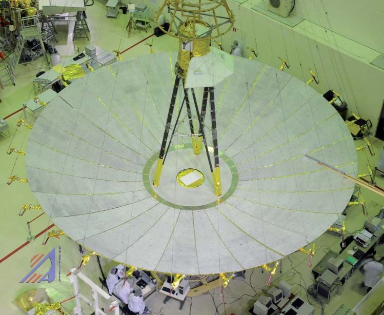
Contents
Editorial ....................................................................................................................... 3
In Memoriam............................................................................................................... 4
Physics of Propagation in a Cellular Wireless Communication Environment...... 5
RadioAstron: An Earth-Space Radio Interferometer with a 350,000 km
  Baseline .................................................................................................................. 22
The International Council for SciencePledges Support for Scientists in the
  L’Aquila Case ........................................................................................................ 29
Book Reviews for Radioscientists ............................................................................ 30
Conferences ............................................................................................................... 34
International Geophysical Calendar 2013 .............................................................. 41
ICEAA - IEEE APWC - EMS .................................................................................. 47
Electromagnetic Metrology Symposium ................................................................. 48
AP-RASC’13.............................................................................................................. 49
URSI F Triennial Open Symposium ........................................................................ 50
Journées Scientifiques............................................................................................... 51
List of URSI Officials ................................................................................................ 52
Information for authors ........................................................................................... 77

Front cover: The 10 m RadioAstron Space Radio Telescope with the petals unfurled. See the paper by N.S. Kardashev, Y.Y.
Kovalev, and I. Kellerman on pp. 22 - 29.

EDITOR-IN-CHIEF                                          EDITORIAL ADVISORY BOARD                                                                EDITOR
URSI Secretary General                                             Phil Wilkinson                                                       W. Ross Stone
Paul Lagasse                                                      (URSI President)                                               840 Armada Terrace
Dept. of Information Technology                                    W. Ross Stone                                                San Diego, CA92106
Ghent University                                              PRODUCTION EDITORS                                                                 USA
St. Pietersnieuwstraat 41                                            Inge Heleu                                               Tel: +1 (619) 222-1915
B-9000 Gent                                                         Inge Lievens                                              Fax: +1 (619) 222-1606
Belgium                                                   SENIOR ASSOCIATE EDITORS                                           E-mail: r.stone@ieee.org
Tel.: (32) 9-264 33 20                                              O. Santolik
Fax : (32) 9-264 42 88                                         A. Pellinen-Wannberg
E-mail: ursi@intec.ugent.be
                                                     ASSOCIATE EDITOR FOR ABSTRACTS
                                                                      P. Watson
                                                   ASSOCIATE EDITOR FOR BOOK REVIEWS
                                                                     K. Schlegel
ASSOCIATE EDITORS                                                                                                For information, please contact :
P. Banerjee & Y. Koyama (Com. A)                                                                                             The URSI Secretariat
                                           S. Paloscia (Com. F)                                                     c/o Ghent University (INTEC)
A. Sihvola (Com. B)                        I. Stanislawska (Com. G)                             Sint-Pietersnieuwstraat 41, B-9000 Gent, Belgium
S. Salous (Com. C)                         M.M. Oppenheim (Com. H)                                   Tel.: (32) 9-264 33 20, Fax: (32) 9-264 42 88
P-N Favennec (Com. D)                      J. Baars (Com. J)                                                                 E-mail: info@ursi.org
D. Giri (Com. E)                           E. Topsakal (Com. K)                                                                http://www.ursi.org

The International Union of Radio Science (URSI) is a foundation Union (1919) of the International Council of Scientific Unions as direct and immediate
successor of the Commission Internationale de Télégraphie Sans Fil which dates from 1913.
Unless marked otherwise, all material in this issue is under copyright © 2012 by Radio Science Press, Belgium, acting as agent and trustee for the
International Union of Radio Science (URSI). All rights reserved. Radio science researchers and instructors are permitted to copy, for non-commercial
use without fee and with credit to the source, material covered by such (URSI) copyright. Permission to use author-copyrighted material must be obtained
from the authors concerned.
The articles published in the Radio Science Bulletin reflect the authors’ opinions and are published as presented. Their inclusion in this publication does
not necessarily constitute endorsement by the publisher.
Neither URSI, nor Radio Science Press, nor its contributors accept liability for errors or consequential damages.

2                                                                              The
                                                                                     Radio Science Bulletin No 343 (December 2012)
Editorial
                Our Papers                                                      the higher its resolution. Achieving baselines
                                                                                larger than an appreciable fraction of the Earth’s
       The problem of the propagation of a                                      diameter requires putting part of the radio
radio wave from a source over a lossy Earth                                     telescope in space. The invited paper by N. S.
is a classic problem, dating back at least to                                   Kardashev, Y. Y. Kovalev, and K. I. Kellermann
the work of Sommerfeld in 1909. As Tapan                                        describes RadioAstron, an Earth-space radio
Sarkar, Walid Dyab, Mohammad Abdallah,                                          interferometer with an effective baseline that
Magdalena Salazar-Palma, M. V. S. N.                                            is more than a factor of 10 larger than what
Prasad, Silvio Barbin, and Sio Weng Ting                                        is possible on Earth. The paper begins with a
demonstrate in their paper, this classic problem                                review of the factors affecting the resolution of
is of considerable current importance. This                                     radio telescopes, and some comparisons with
is because it provides new and significant                                      optical telescopes. This is followed by a brief
insight into the science of electromagnetic propagation for         introduction to radio interferometry. The use of independent
cellular communications systems. The paper begins with a            oscillators located at the elements of an interferometer,
review of the history of this problem. Several controversies        along with remote recording of the data, are explained.
surrounding the existence and nature of various types of            These techniques remove two of the limitations to the
surfaces waves are explored in detail. The basic questions of       baselines of very-long-baseline interferometry. Two earlier
what constitutes a surface wave, and under what conditions          space-based long-baseline interferometers are reviewed.
a surface wave is associated with such propagation, are             The development and specifications of RadioAstron are
addressed. The controversies surrounding such surface               then reviewed. This instrument consists of a 10 m dish in
waves are resolved. This includes showing that the source           space that works with a variety of Earth-based dishes in
of an error in Sommerfeld’s 1909 paper was not due to a             many different countries to provide a number of different
sign error, as often claimed, but was rather due to a more-         observing opportunities. The spacecraft was launched in
subtle mathematical issue. In a companion paper, the authors        July 2011. The space dish is in a highly elliptical orbit,
have shown that the electromagnetic fields associated with          providing a baseline of as much as 350,000 km. The
propagation in a cellular-communications cell decay over            system operates in four bands, from 330 MHz to 22 GHz.
most of the cell with distance at a rate of 30 dB per decade,       The details of the hardware and the data system are given.
followed by a fringe region where the rate of decay is 40 dB        The scientific goals of the project are reviewed, and early
per decade. This paper derives the fields that are responsible      results are summarized. This paper provides a very nice
for this fading. Among other results, it is shown that the fields   review of space-based radio telescopes and RadioAstron.
produced by a two-dimensional source, or by a line source,          It also contains good resources for those seeking additional
over an imperfectly conducting ground produce the initial           information.
fading rate. It is further shown that fields in the form of a
Norton surface wave contribute only in the fringe region of              This paper is one of the invited Reviews of Radio
the cell. A variety of experimental data related to the decay       Science from Commission J. The assistance of Ondrej
rate of fields over imperfectly conducting media is cited and       Santolik and members of Commission J in bringing us this
examined in detail, and shown to support the theoretical            paper are gratefully acknowledged.
conclusions. This includes classic experiments done in the
1930s specifically to investigate surface waves, as well as                  Our Other Contributions
modern experiments with cellular communication systems.
This leads to a clear and accurate physical representation
of the fields associated with such systems. One of the most              Thanks to Kristian Schlegel, we again have two book
interesting consequences of this representation is that the         reviews in this issue. One is from a Young Scientist, and both
basic propagation path losses for such systems are insensitive      cover books that the reviewers found to be quite valuable.
to the details of the propagation environment: a macro
model is sufficient to accurately provide the basic path                 There are several calls for papers for important
losses. This paper is important reading for anyone with an          conferences for radio scientists in this issue. As readers
interest in either the classical problem of propagation over        may have noticed from the previous issue, we are now
an imperfectly conducting medium, or in the propagation             running the complete calls for papers as provided by the
associated with modern cellular communication systems.              conferences. This should provide more information for our
                                                                    readers. We also have a report on a COSPAR session on
     Fundamental physics says that everything else                  “Global and Regional Representation of Ionospheric Peak
being equal, the larger the baseline of a radio telescope,          Parameters for Space Weather Applications.” The summary

The
      Radio Science Bulletin No 343 (December 2012)                                                                             3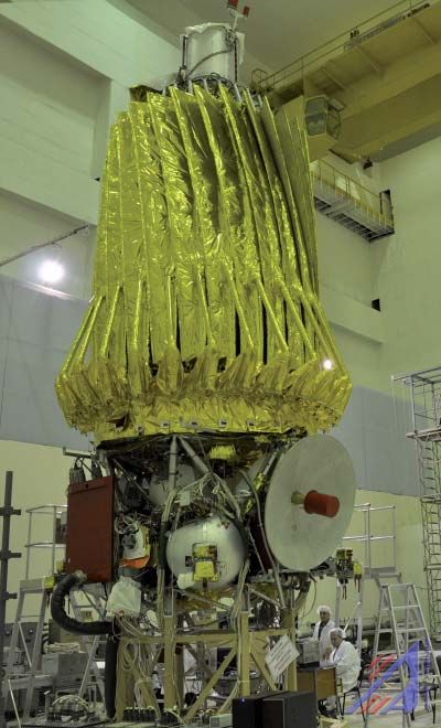
provided of the results should be of interest to anyone using                       Best Wishes
ionospheric models.

     This being the December issue, our usual updated                  This issue should reach the URSI community around
material on the organization of URSI and key contact people      the middle of December. My very best wishes to all of our
within the Union is included.                                    readers for most joyous holidays, and for a very happy,
                                                                 healthy, safe, and prosperous New Year!

                                            In Memoriam
                                                VLADIMíR FIALA
                                                 1938 - 2012
     Vladimír Fiala, an internationally                                      to our understanding of the physics of probes
recognized space-plasma physicist, a former                                  and antennas in space plasmas. He researched
Chair of URSI Commission H (Waves in                                         and explained the behavior of magnetic and
Plasmas), and a former President of the Czech                                electric antennas in the context of planning or
National Committee of URSI, passed away on                                   of data analysis for the FR-1 (France/NASA),
September 8, 2012, after a courageous fight                                  Aktivnyi (USSR), CLUSTER (ESA), and
against cancer.                                                              OEDIPUS-C (Canada) missions. Dr. Fiala also
                                                                             took up and advanced the study of the probe-
      Dr. Fiala graduated from the Department                                antenna response to waves propagating close to
of Mathematics and Physics of the Charles                                    plasma resonances. These included the oblique
University in Prague in 1961. After doing post-                              resonance occurring in anisotropic plasmas in
graduate studies in the Lebedev Institute of                                 the whistler mode, and the Langmuir-wave
Physics in Moscow with Alexander Gurevich,                                   resonance in a drifting isotropic plasma.
he received his PhD in space-plasma physics
from the Geophysical Institute of the Czechoslovak                     Vladimir Fiala was a keen proponent of international
Academy of Sciences in 1967. From 1967 to 1970, he               groups for working-level collaboration, as was evidenced
worked in the Groupe de Recherches Ionospheriques/               by his organizational work in URSI. He championed and
CNRS in France with L. R. O. Storey, and then returned           organized international group studies on diverse aspects
to Prague to work in the Geophysical Institute. He also          of waves in space plasmas. A NATO Linkage Grant that
lectured on space physics at Charles University. In addition,    he initiated led to the birth of the Resonance Cone Club
for several years he worked in France, Russia, and the           consortium involving Russia, the Czech Republic, France,
United States in various space-research laboratories on          and Canada, which is just one example among many of his
long-term fellowships. In 1994, he received a Fulbright          commitment to international scientific cooperation.
Research Award to work at the University of Minnesota.
For the rest of his life, he then worked in the Department             Dr. Fiala was a talented scientist, and he loved his
of Space Physics, Institute of Atmospheric Physics of the        work. He had a gift for sharing his enthusiasm with younger
Academy of Sciences of the Czech Republic.                       colleagues, whom he was always ready to help to do good
                                                                 scientific work. His deep voice and his sense of humor
      Vladimir Fiala was elected Vice Chair of URSI              impressed all those who had the privilege of working with
Commission H at the 1993 Kyoto General Assembly. He              him. Discussions with him were open, thoughtful, pleasant,
became Chair of that Commission at the 1996 Lille General        and inspiring. He will be sorely missed.
Assembly. From 1999 until 2008, he worked as the President
of the Czech National Committee of URSI. The research                 Edited by O. Santolik (Institute of Atmospheric
interests of Vladimir Fiala were in theoretical space plasma     Physics in Prague, Czech Republic; e-mail: os@ufa.cas.
physics, especially antenna-plasma interaction, propagation      cz), Chair of URSI Commission H, with significant help
and excitation of plasma waves, and wave scattering by           from L. R. O. Storey and H. G. James
ionospheric irregularities. He significantly contributed

4                                                               The
                                                                      Radio Science Bulletin No 343 (December 2012)
Physics of Propagation
in a Cellular Wireless Tapan K. Sarkar
W. Dyab, M. N. Abdallah
Communication Environment M. Salazar-Palma
M. V.S.N. Prasad
S. Barbin, S. Weng Ting
Abstract paper is hence to develop an understanding of the physics
associated with radiating fields that decay with a rate of
30 dB per decade with distance, and with an emphasis on
The objective of this paper is to illustrate from the following phenomena:
a physics standpoint the nature of the fields that carry
energy from a transmitter to a receiver located over an 1. To illustrate that radiation fields emanating from a two-
imperfectly conducting Earth. In an accompanying paper dimensional source and associated with the launching
[1], it was shown from both the theoretical (developed of a true surface wave are responsible for producing a
from the classical Sommerfeld attenuation function) and field that decays as 30 dB per decade. This type of field
experimental points of view that the fields inside a cellular- can also be generated from a line source located over
communication cell decay as 30 dB per decade, following an imperfectly conducting ground.
a slow fading region. The 30 dB per decade region is
followed by a region (in the fringe area) where the rate 2. To illustrate that radiation fields in the form of Norton’s
of decay is 40 dB per decade. This means that the fields surface wave contribute only in the fringe areas of the
decay as 1 1.5 (where is the radial distance between cells, where the fields decay as 40 dB per decade.
the transmitter and the receiver) and 1 2 , respectively,
inside a cell. The first goal is to illustrate that Sommerfeld 3. To illustrate that the error in Sommerfeld’s classical
had no error in sign in his classic 1909 paper. However, while paper of 1909 had nothing to do with an error in sign.
computing his asymptotic development of the branch-cut He did not consider the effect of the occurrence of a
integral, Sommerfeld did not notice that beside the space pole near the saddle point in his asymptotic expansion.
wave, this contains the surface wave with a negative sign, In other words, the poles were not located on the proper
which would cancel the residue of the pole. In other words, Riemann sheet. The popular belief that he made an error
no surface wave can be generated from a pole that is a part of in sign in his paper is indeed a myth!
the original Sommerfeld solution for radiation from a dipole
operating over an imperfectly conducting ground. Other 4. To illustrate that the electromagnetic field produced
type of waves, e.g., Norton’s surface wave and a radiation in a cellular communication system (where the dipole
field that decays as 1 1.5 , are part of the ground wave. constituting the base-station antenna is placed at a given
They can be derived from the same Sommerfeld attenuation height over the imperfectly conducting surface of the
function, but using different types of approximations. As Earth) is due to an infinite set of images starting at the
already mentioned, Norton’s surface wave and the radiation location of the image of the first point of the transmitting
field (decaying as 1 1.5 ) are a part of the solution. These antenna and extending to negative infinity, resulting in
points were illustrated in an accompanying paper [1]: a line source. This will be illustrated by both theoretical
here, we focus on the physics of these waves. We also and experimental data. This further illustrates that ray
explain what the mathematical characteristics of a surface tracing is not the appropriate tool to use in predicting
wave are, as there is a lot of confusion in the usage of the the fields near the ground.
same word for different types of waves. The goal of this
Tapan K. Sarkar, Walid Dyab, and Mohammad N. Abdal- Dr. K. S. Krishnan Road, New Delhi-110012, India; e-mail:
lah are with the Department of Electrical Engineering and mvsnprasad@gmail.com; Silvio Barbin is with the Depar-
Computer Science, Syracuse University, Syracuse, New York tamento de Engenharia de Telecomunicações e Controle
13244-1240, USA; e-mail: tksarkar@syr.edu; http://lcs.syr. Escola Politécnica da Universidade de São Paulo, São
edu/faculty/sarkar/; Magdalena Salazar-Palma is with the Paulo, Brazil; e-mail: barbin@usp.br; Sio Weng Ting is with
Dept. of Signal Theory & Communications, Universidad the Department of Electrical Engineering and Computer
Carlos III de Madrid, Avenida de la Universidad, 30, 28911 Science, University of Macau, Av. Padre Tomas Pereira,
Leganés, Madrid, Spain; e-mail: salazar@tsc.uc3m.es; M. Taipa, Macau, China (CIE); e-mail: tonyting@umac.mo.
V. S. N. Prasad is with the National Physical Laboratory,
The
Radio Science Bulletin No 343 (December 2012) 5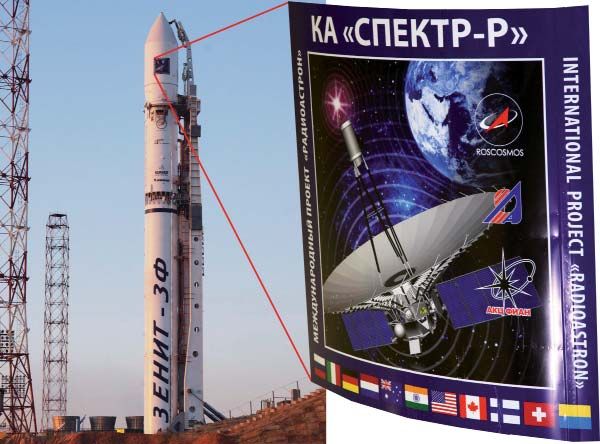
5. Finally, to illustrate that all the experimental data terminology of the various waves that we use in this paper.
indeed clearly show that the path-loss exponent The guiding of a plane electromagnetic wave along the flat
in a cellular environment is three (at moderate interface separating air and the imperfectly conducting
distances from the transmitting antenna) or ground seems to have been first investigated by Cohn
four (at larger distances), in spite of buildings [12], and shortly thereafter by Uller [13]. Zenneck [14, 15]
and trees being present in the measurements. recognized the bearing of this research on the propagation
Hence, one of the surprising conclusions is that of radio waves, and showed that the field equations admit
one can get by with macro modeling, and micro a solution that can be interpreted as a surface wave guided
modeling of the environment is overkill! by a plane interface separating any two media.
As further stated by Schelkunoff, according to
1. Discussion of the Zenneck [15],
Early History
...there are waves which emanate from a transmitter
As presented by Wait [2] and Collin [3], in the placed in a homogenous insulating material and energy
19th century – after the initial work of Hertz [4] and is radiated in straight lines, radially from the transmitter.
Heaviside [5], and exemplified by Lodge [6] and followed Consequently, the energy varies as 1 2 ( distance
through by Tesla [7], Popov [8], Bose [9], and others – from the source) and the amplitudes of the electric and
researchers had irrefutable evidence of the correctness magnetic field strengths vary as 1 , which are termed
of Maxwell’s equations, and the ability to generate and as space waves. A different kind of wave is obtained
radiate electromagnetic waves. However, it was Marconi for an antenna located at the Earth’s surface. The wave
[10] who translated all these principles into reality, by emanated into the air by an antenna at the Earth’s surface
transmitting electromagnetic waves over long distances. It may be conceived as consisting of two parts, one of
was Marconi who proved to the scientific community that which is of the nature of a space wave and the other
besides the line-of-sight communication, other modes of of a surface wave. In the former, the energy 1 2 ,
communication were possible. The conjecture at that time the amplitude therefore varies as 1 ; in the latter,
1
was that perhaps the transmission over such large distances the energy , and therefore the amplitude 1
The fact that in the latter there is a decrease in energy
took place through the surface wave, introduced earlier by
Lord Rayleigh [11]. as the distance increases in contrast to a wave following
a wire – and in addition to and entirely aside from such
According to Schelkunoff [11], it was Lord Rayleigh absorption as occurs – is explained by the fact that the
who discovered that in a semi-infinite elastic medium, a energy is spreading itself out over in ever-increasing
source of finite dimensions excites two kinds of waves: 1) circles as the wave propagates. This much is relevant
space waves that spread in all directions, and 2) surface to the classical distinction between space and surface
waves that spread only along the boundary. If the medium is waves. Therefore, initially Zenneck and Sommerfeld
non-dissipative, it follows from the principle of conservation accepted Rayleigh’s definition of a surface wave as far
of energy that at large distances from the source, the energy as the most significant physical properties are concerned.
density in a space wave varies inversely as the square of However, later they have made an unfortunate slip in
the distance from the source. In a surface wave, it varies their analysis which subsequently confused the issue
inversely as the distance. This implies that the fields of a [11]. The controversy thus arose from the following
space wave vary as the inverse of the distance, while those statement of Zenneck [15]: While at short distances from
of a surface wave should vary as the inverse of the square the transmitter, the waves are almost entirely of the nature
root of the distance. Surface waves seemed to be attached of space waves, as the distance increases the surface
to the boundary of the solid, and tended to follow it, even component becomes more and more predominant, as its
if it was curved. amplitude decreases more slowly than that of the space
component. That is the nature of the wave constantly
In the time of Marconi’s famous experiments, and prior approaches that of a surface wave. When the distance
to the discovery of the Kennelly-Heaviside reflecting layer, becomes very great, the surface wave may again give
there was much speculation about the possible existence way to the space wave, as the former is more rapidly
of similar kinds of electromagnetic waves. It was already absorbed. It is questionable, however whether this effect
known that electric waves had a tendency to cling to parallel is of practical importance.
wires (Lecher wires, as they are called), and could thus be
guided around corners. Did the surface of the Earth have The above-quoted conclusion of Zenneck’s is based
a similar tendency to capture some of the energy from an on the original formulas obtained by Sommerfeld. However,
antenna and guide it into the shadow region, thus explaining it was found later both from theory and experiment that
Marconi’s success? That was the question! the surface-wave term was missing from the final solution
initially proposed by Sommerfeld.
This created a great interest in the study of surface
waves. For completeness, in the Appendix, we define the
6 The
Radio Science Bulletin No 343 (December 2012)
Wait [2] also stated that the idea that a Zenneck type
of wave could be employed to investigate the propagation
J 0 k22 2 k12 k12 2 k22
2 k12 k22 2 k12 k12 2 k22
of fields over the Earth was pointed out both by Zenneck
himself, and his colleague, Hack [16]. In 1907, Zenneck
0
[14, 15] showed that a plane interface between two semi-
infinite media, such as the ground and the air, could support
an electromagnetic wave that is exponentially attenuated in
the direction of propagation along the surface, and vertically exp 2 k12 z z d
(1)
upwards and downwards from the interface. Zenneck
showed that Maxwell’s equations did provide a solution
for a wave or an inhomogeneous plane wave that was
attached to the interface between the air and the underlying for Re 2 k1,2
2
0 . Here, k12 2 0 0 , and
2 2
medium, and could propagate over great distances with a k2 0 0 , where 0 is the permeability of vacuum.
small amount of attenuation [15]. Zenneck did not show Furthermore,
that an antenna could generate such a wave, but because
this “surface wave” seemed to be a plausible explanation
of the propagation of radio waves to great distances, it was
accepted. A Zenneck wave is an inhomogeneous plane I dz
P , (2)
wave, because the field decays (exponentially in this case) j 4 0
over the wavefront with an increase in the distance from
the surface. A wave propagating along the x direction
with a phase velocity greater than the speed of light has
a magnetic-field distribution in air given by the real part x x 2 y y 2 , (3)
of the corresponding phasor quantity, multiplied by e jt ,
where stands for the angular frequency corresponding
to the frequency of operation, t stands for the time variable,
and j is the imaginary unit. In a phasor notation, this term
is suppressed, as H z Ae y e ux , where j R1 2 z z ,
2
(4)
The phasor components of the electric fields are given
b y Ex A e y eux a n d E y A u e y eux
j for
Here, 0 stands the j (x,y,z)
dielectric constant of vacuum,
are the Cartesian coordinates of the observation point, and
R2 2 z z
2
A is a constant. This wave decays exponentially with the .
complex propagation constant u along the x direction, and
also decays exponentially along the y direction, with the
propagation constant, . Typically, these types of waves
have a phase constant in vacuum that increases as the where is the variable of integration; ( x, y , z ) is
wavelength decreases, while the rate of evanescence is small the location of the dipole, placed vertically with respect to
and independent of the frequency [11]. As mentioned before, the Earth’s surface; and I dz is the dipole moment of the
the characteristics of various waves are summarized in the elementary current.
Appendix. The Zenneck wave is not a true surface wave
according to our use of Schelkunoff’s characterization, as As part of his solution, Sommerfeld illustrated that
explained in the next section. a surface-wave contribution arose from the pole of the
integrand (i.e., from the solution for of the equation
In 1909, Sommerfeld [17, 18] undertook a detailed k22 2 k12 k12 2 k22 0 ), and other radiated
analysis of the radiation from an infinitesimal vertical waves evolved from the branch-cut contributions related
Hertzian dipole over an imperfectly conducting infinite to the two branch points located at k1 and k2 . It was
ground medium, to complete the demonstration of the recognized from the onset by Sommerfeld that his total
surface-wave component of the total field. Sommerfeld solution of Equation (1) could be interpreted as a bundle of
obtained the phasor for the potential from a dipole located plane waves reflected and refracted from the surface of the
in air (medium 1, with a propagation constant k1 ) and Earth at various angles of incidence. The surface integrals
radiating over a ground plane having a complex permittivity were extended over the plane Earth and over small spheres
(medium 2, with a propagation constant k2 k1 ), as that excluded the singularities occurring at the source and
at the point of observation. The mathematical details are
available in [1]. Sommerfeld’s approach was based on
a deformation of the path of integration in the complex
exp jk1R1 plane, as shown in Figure 1a. The denominator for
1z P
R1 the expression of the fields has branch points at k1
k1k2
and k2 , and poles at P . The
k12 on
corresponding Riemann surface has four sheets; k22only one
The
Radio Science Bulletin No 343 (December 2012) 7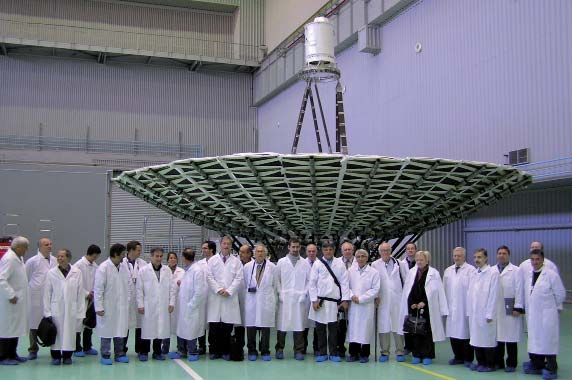
Figure 1a. The closed contour of integration as imple- Figure 1b. The actual location of the pole in the
mented by Sommerfeld in the lower complex plane. lower complex plane.
of these are the necessary conditions for the convergence of
the integral at infinity fulfilled. According to Sommerfeld,
the path of integration can be resolved on this sheet into
three parts. The first part is a loop from infinity about the
branch point k1 the second part is a similar loop about
k2 , and the third part can be any small circle about
the pole P , as seen in Figure 1a. The contributions of
the loops about the branch points give the dominant terms
jk1R jk2 R
at e and e , which can be identified as the space
waves. R The residueR at the pole has a variation of the form
e jP R , which had all the hallmarks of a true surface wave,
but Rnot a Zenneck wave. (We will discuss the properties of a
surface wave in the next section. However, suffice it to say Figure 1c. The contribution of the pole generating
that it is a slow wave for a lossless dielectric medium and the surface wave is excluded when the branch-cut
there is practically no loss in the direction of propagation. contour is chosen vertically (Kahan and Eckart
The fields in the transverse directions are evanescent, and [22], Baños [6, pp. 55]).
as the frequency increases, the wave is confined close to
the surface. However, it is not a Zenneck wave, as it is a
slow wave.) Here, R is the distance between the source and a surface wave, but the Weyl surface wave is not identical
the observation (field) point. The mathematical subtleties to that of Sommerfeld [17] and Zenneck [15].
that differentiate a surface wave from a Zenneck wave are
explained in the next section. In 1926, Sommerfeld returned to the same problem.
That time, he solved it [22] using a different approach, and
Sommerfeld thus obtained results that lent considerable confirmed the correctness of Weyl’s solution [23]. With a
credence to Marconi’s view that the electromagnetic wave better understanding of the ionospheric mode of propagation,
was guided along the surface. As Collin noted in [3], as the concept of the surface wave being the important factor
early as 1902, Kennelly [19] and Heaviside [20] predicted for long-distance propagation lost favor. It is the presence
the existence of an ionized layer at a considerable height of the Kennelly-Heaviside layer of the ionosphere that
above the surface of the Earth. It was thought that such is responsible for the long-distance propagation of the
a layer could possibly reflect the electromagnetic waves long-wavelength fields. In 1930, Van der Pol and Niessen
back to the Earth. This was experimentally verified by published a new solution to the old Sommerfeld problem,
Brett and Tuve in 1926 [21]. No serious challenge to the using yet another method of solution [24]. Again, the
surface-wave mechanism for long-distance propagation results of Weyl and the later results of Sommerfeld were
thus occurred until a decade later, when Weyl published a confirmed. This was followed by another paper of Van der
paper on the same subject. Weyl obtained a solution very Pol on the same problem [25]. Each independent solution
similar to that found by Sommerfeld [17], but without the of the old Sommerfeld problem agreed with Sommerfeld’s
surface-wave term [23]. Weyl [23] obtained an asymptotic 1909 solution, except for the surface-wave term.
series representing the diffracted field by applying a method
of steepest descent. Weyl’s solution also reduces to a form In the 1930s, Norton undertook the task of reducing
that can be interpreted as the superposition of a space and the formulas of Van der Pol and Niessen to practical form
for the radio engineer [26-28]. As a part of this undertaking,
8 The
Radio Science Bulletin No 343 (December 2012)
he apparently believed that he had found a sign error in However, he never admitted to an error in the sign in his
Sommerfeld’s 1909 paper. In 1935, Norton published a 1909 paper! Referring to F. Noether [37], he attributed this
short paper in which he asserted that Sommerfeld had made to an inaccuracy in the evaluation of his general solution.
an error in sign in one of Sommerfeld’s formulas [28]. According to Noether’s explanation, the pole is so close to
Unfortunately, Norton did not provide any specific details one of the branch cuts that the integration method used by
as to which of Sommerfeld’s expressions had the sign error, Sommerfeld was possibly not sufficiently reliable.
or what had gone wrong in Sommerfeld’s analysis. In 1937,
Niessen published a paper in which Niessen also claimed As Baños pointed out, Stratton [38, p. 585]
that Sommerfeld had made a sign error in Sommerfeld’s summarized the above (confused) situation by saying that
1909 paper [29]. According to Niessen, the sign error from the point of view of practical applications, the result
came about because Sommerfeld did not take the value of Sommerfeld and the charts of Rolf [39] based on them
of the argument of the square root of a complex number were not reliable when the electric displacement current in
using the convention that this should always be taken to the conducting medium was appreciable, for example, at
be between 0 and 2 . high frequencies. According to Brekhovskikh [40, p. 270]
the question of the existence of Sommerfeld’s surface wave
Charles Burrows of the Bell Laboratories [30, 31] was first properly clarified by Ott [41], who combined the
carefully measured the field strength at 150 MHz for a methods of Weyl and Sommerfeld, and devised a method
distance ranging from 1 m to 2000 m over a deep, calm of effective saddle-point integration when there exists a
lake near Seneca, in upper New York. He showed that first-order pole in the vicinity of the saddle point. In effect,
his measured results did not support a surface wave. His Ott was thus able to re-derive Sommerfeld’s results of 1926
experimental results were conformed with the Weyl-Norton in a more-efficient manner [42].
theory, namely that in the far field, a surface-wave type
phenomenon is not observed. Burrows further concluded Baños [42] further stated that despite Ott’s valuable
that these results, along with the experiments, proved that contribution on the question of the existence or nonexistence
simple antennas do not generate a Sommerfeld surface of Sommerfeld’s electromagnetic surface wave, this topic
wave [31]. continued to be debated in the literature. In 1947, Epstein
[43] published a paper in which he disqualified Sommerfeld’s
In addition, Wise [32] published a paper that showed original formulation of the problem by proposing a new
that a vertical dipole does not generate a surface wave that contour of integration excluding the pole, which was shown
at great distances behaves like Zenneck’s plane wave or a to be in error by Bouwkamp [44]. Kahan and Eckart [45,
surface wave. A contemporary theoretical investigation by 46] next published a series of papers. They got their acts
S. O. Rice [33] led to the same conclusion. right in the latter papers, where they claimed, according to
Bouwkamp [44], to accept Sommerfeld’s original solution,
In spite of the apparent closure of the analytical and pointed out that Sommerfeld’s evaluation of the integral
debate, the controversies would not die. The late Kenneth around the branch cut was in error. They stressed that the
Norton, an eminent radio engineer in the USA, exchanged correct evaluation would have yielded an expression that
numerous letters with Sommerfeld on this topic. An example contains the surface wave with negative sign, so that the
is a letter [34] from Sommerfeld to Norton, which was real result would have coincided with Weyl’s result, the
written while the former was on holiday in the Austrian negative surface-wave term being cancelled by the positive
Tyrol. Sommerfeld never agreed that an error or miscue term due to the residue of the pole of the integrand. This
had ever been made. Two later letters from Norton [35, will happen because the true location of the poles was not
36] indicated his views on the separation of surface waves as shown by Sommerfeld in Figure 1a, but more like the
and space waves. Sommerfeld acknowledged Norton’s situation in Figure 1b. When the saddle path of integration
communications, and suggested he compare his results with is changed from Figure 1b to that of Figure 1c, the pole
those of Van der Pol and Niessen [24]. Of course, there is a will thus again come into the picture. This explanation and
consistency here, because Norton [26-28] based his papers clarification of the controversy was similar to that of Wise
on the results of Van der Pol and Niessen [2]! [32] and Rice [33], who showed that the existence of a
surface wave is not a part of the total solution.
As stated by Wait [2], the confusion was also caused
when, in 1926, Sommerfeld [22] published a paper where In summary, the correct location of the surface-wave
Sommerfeld revisited his old paper of 1909, and changed pole is illustrated in Figure 1b. When the branch-cut integral
the sign of the argument of the complex error function is evaluated along the vertical lines as shown in Figure 1c,
without any proper explanations. Subsequently, there have the integral over the cut must thus consequently contain
been many speculations that in the 1909 paper, Sommerfeld the surface wave with an opposite sign. In other words, the
had an error in the sign, which he corrected in the 1926 surface-wave pole is not located in the appropriate sheet.
paper. Since Weyl’s method seemed mathematically simpler, This is also what was shown in Baños [42, p. 55], similar
Weyl’s result was favored by public opinion in numerous to Figure 1c. It turns out that when the contribution from
papers by other authors. Finally, in 1935, Sommerfeld the pole is included in the solution, there appears to be a
himself conceded that the surface wave had no reality. discrepancy in the sign as outlined in Sommerfeld’s 1909
The
Radio Science Bulletin No 343 (December 2012) 9
paper. This can also be seen from the branch-cut integrals, 2. What is a Surface Wave?
as illustrated in a companion paper [1]: the saddle path
never crosses the pole, and therefore their contribution is
not relevant. This sentiment – that nothing was wrong with As explained by Barlow and Cullen [49], a surface
a sign in Sommerfeld’s paper – was echoed by Collin [3] wave is a wave that propagates without radiating energy
and Karawas [47]. However, the error in sign is not the along an interface between two different media. If both
issue. The important point is that the surface-wave pole is media have finite losses, the energy directed along the
on the wrong Riemann sheet, and should not come into play. interface will be required to supply the losses in the media.
This does not invalidate the description of the surface wave
However, the most succinct and clear explanation is if radiation is construed to mean that energy is absorbed
available in Schelkunoff’s book [48], which, interestingly is from the wave independently of the media supporting it. The
not referenced in any of the papers. In his book, Schelkunoff surface-wave phenomenon arises primarily from its unique
[48, p. 430] categorically states “that the denominator of the nonradiating characteristic. This enables high-frequency
term inside the brackets in equation (1) can have no roots, energy to be transferred intact from one point to another,
the integrals can have no poles, and there are no surface except in so far as demands are made upon that energy to
waves. This conclusion is contrary to that reached by early compensate for the losses in the two media. This definition
writers on the subject.” agrees with the concept of Rayleigh, as we discussed in the
previous section. However, the next statement of Barlow
Schelkunoff then proves his point by substituting the and Cullen [49] stated that the three distinctive forms of
solution for the pole into the equation. When we substitute the surface wave, namely,
k1k2
P into the equation
k12 k22 1. the Zenneck or inhomogeneous plane wave supported
by a flat surface,
2. the radial cylindrical wave also supported by a flat
k12 2 k12 2 k22 surface, and
3. the Goubau [56, 57] or axial cylindrical wave associated
k2 2
2
k12 k12 2
k2 2 with a transversely cylindrical surface,
represent basically one and the same phenomenon from
0 their field distribution. This can cause some anxiety, as
we will soon see.
for the pole, it then becomes clear that
In addition, Barlow et al. pointed out that Sommerfeld’s
theory for ground-wave propagation over a flat Earth also
introduced a so-called surface wave. Sommerfeld divided
k22 P2 k12 k12 P2 k22 the ground wave into two components, which he respectively
called a “space wave” and a “surface wave.” The surface-
wave component is represented by one of the terms in the
analysis of the total field, and its particular feature is that it
k12 k22 k12 k22
k2 2 k12 k12 k2 2 needs to predominate near the Earth’s surface. Both parts
k12 k2 2
k12 k2 2
are required to satisfy Maxwell’s equations. At long ranges,
according to Sommerfeld, the surface-wave part varies
inversely as the square of the distance, which is identical
to the Norton surface wave. In similar circumstances, a true
k22 k14 k12 k24 0 . surface wave, radiated from a vertical line source over a
horizontal surface, would be expected to decay exponentially
with range, owing to losses. At the same time, it would be
There thus does not appear to be any surface wave in
expected to fall in amplitude inversely as the square root of
the final solution, a conclusion that everybody agrees with,
the range, due to the expanding wavefront. In Sommerfeld’s
and which Schelkunoff pointed out about 70 years ago [48]!
original 1909 paper, a surface wave of this type appeared
in the expression of the total field, which was later shown
Next, we will observe what the mathematical
not to exist.
properties of a classical surface wave are, so as to eliminate
the confusion associated with the use of this word, and the
In addition, Wait [52] also provided a clarification
turmoil it caused when Sommerfeld introduced the term
between the terms surface waves and ground waves, which
surface wave in his solution. In addition, the difference
are the fields observed at the interface. According to Wait,
between a classical surface wave and a Zenneck wave will
“A surface wave is one that propagates along an interface
also be illustrated.
between two different media without radiation; such
10 The
Radio Science Bulletin No 343 (December 2012)radiation being construed to mean energy converted from Schelkunoff [11] pointed out that these same words, surface
the surface wave field to some other form,” according to wave, convey different meanings to different individuals.
the definitions of Barlow and Cullen [49] and Cullen [53]. According to Schelkunoff, the preliminary list of different
surface waves, compiled by Dr. James R. Wait, the then
The ground wave is characterized per the IEEE chair of a working group of URSI, mentioned 11 types of
definition [50, 51]: “A radio wave that is propagated over surface waves in the light of propagation of plane waves
the Earth and is ordinarily affected by the presence of in two semi-infinite, nonmagnetic, non-dissipative media,
the ground and troposphere. The ground wave includes separated by a plane boundary. These 11 types of surface
all components of a radio wave over the Earth except waves consist of
ionospheric and tropospheric waves.”
1. Zenneck Surface Wave (at the interface of two half-
The situation is particularly confused since in the spaces having different dielectric constants),
IEEE test procedures, the surface-wave component of the
ground wave was completely different from the definition 2. Sommerfeld Surface Wave (a dipole over a conducting
used by Barlow and Cullen [49]. Wait [52] tried to clarify half-space),
this state of confusion by adopting a model that would
encompass all forms of waves that can propagate over an 3. Norton Surface Wave (a dipole over a conducting half-
interface. This was carried out by expressing the total field space),
from a vertical electric dipole at a height, h, radiating over
an air-Earth interface. The vertical electric field at a vertical 4. Sommerfeld Axial Surface Wave (an imperfectly
height, z, and a horizontal distance, , could be written in conducting cylindrical wire),
the following form, consisting of three terms:
5. Goubau Axial Surface Wave (a dielectric-coated wire),
E Ea Eb s , 6. Plane Trapped Surface Wave (a dielectric-coated
plane conductor, corrugated surface, or other inductive
boundaries),
where Ea is the field that would be computed on the
basis of geometrical optics. Eb and Es are the surface 7. Cylindrical Trapped Surface Wave (the same as above
waves, which are entirely different in character from one in cylindrical form),
another. If the phase angle of the surface impedance is less
than 45° [42], it was shown that Es was not present. Eb 8. Plane Quasi-Trapped Surface Wave (a stratified
could then be identified as a correction to the geometrical- conductor when the surface impedance has both a
optics field, Ea . Asymptotically, Eb varies as 2 , whereas resistive and inductive component),
Ea varies as 1 . In many high-frequency applications,
Ea is thus dominant. However, at shorter distances and/or 9. Cylindrical Quasi-Trapped Surface Wave (the same as
lower frequencies, when the asymptotic form for E is not above in cylindrical form),
valid, it turns out that Eb may be very important, and that
it should be called a Norton surface wave [26, 27], rather 10. Azimuthal Surface Wave (on dielectric-coated and
than just referring to it as a surface wave. corrugated cylinders and spheres, for propagation in
the azimuthal direction),
When the phase angle of the surface impedance
becomes greater than 45°, the contribution, Es , is finite. In 11. Composite Axial-Azimuthal Surface Wave (the same as
many cases, it dominates Ea and E . For example, it may above when propagation has a component in both the
1b
be shown that [54] Es varies as 2 for a purely inductive axial and azimuthal directions).
boundary. The contribution Es , which is not present for
a homogenous conducting half-space, is really a trapped As a group these wave types have no important
surface wave, since the energy is confined to regions near physical properties in common. Calling these wave types by
the interface. It is suggested that this component of the total the same name, even with qualifying adjectives, encourages
field be described as the Barlow surface wave. It is of interest one to assume that the most significant physical properties
to note that at least formally, Es has the form of a Zenneck of one wave type are shared by other wave types and can
wave for the case of a homogenous Earth. As discussed cause serious misunderstandings [11].
in [49], it is not excited by a physically realizable source.
As Schelkunoff explained [11], when a wave is
From these various interpretations of the term surface incident at an air-dielectric boundary, then there can be
wave, it is very easy to get confused. We hence take recourse partial transmission and partial reflection, in the form of
to Schelkunoff [11], as he clarified the situation from a radiation, from the boundary. However, if the wave contains
mathematical perspective, and presented the definition of a component the magnetic field of which is parallel to the
what a surface wave is in the true classical sense of Rayleigh. boundary and the wave is incident at a Brewster’s angle,
The
Radio Science Bulletin No 343 (December 2012) 11then the wave will be totally transmitted to the dielectric. If situation that we are analyzing. According to Schelkunoff,
there is a reflected wave, it will be horizontally polarized, a dipole radiating above an interface between two media
as the Brewster’s angle applies only to vertically polarized thus does not produce any true surface wave as defined
waves. The Brewster’s angle is thus associated with the by Lord Rayleigh. Moreover, the term Norton “surface
zeros of the reflection coefficient (zeros of the numerator wave” [50, 51] is not related to any of the surface waves
of the term placed inside brackets in Equation (1)). If the discussed so far. This wave was defined as the difference
medium is slightly lossy, then again there will be minimal between the exact field of a dipole above an imperfect
reflection from the boundary. In this case, the wave is not ground and the field calculated by the rules of geometrical
tied to the boundary. The Brewster’s angle is independent of optics, as explained in the Appendix. This is exactly the
the frequency and so is the exponential rate of attenuation same definition used in the IEEE Standard Definitions
of this wave with the increasing distance from the interface, of Terms for Radio Wave Propagation [50]. This Norton
which is small. The phase constant in vacuum increases “surface wave” does not even satisfy Maxwell’s equations.
with the decrease in the wavelength for this wave. If the There is also the term ground wave, which is also defined
dielectric medium has a finite conductivity, then there in the IEEE Standard Definitions of Terms for Radio Wave
may be an attenuation at right angles to the direction of Propagation [50]. It is the total wave (the space wave plus
propagation. The wave is also a fast wave, and essentially the surface wave) that would have existed in the proximity
passes through the dielectric medium without seeing it. The of the ground if the Kennelly-Heaviside layer was absent
first four of the eleven wave types listed above belong to [50]. Schelkunoff further clarified the situation by stating
this class, and are therefore not true surface waves in the that a wave reflected from the ionosphere is defined as the
classical sense [11] of Lord Rayleigh. sky wave. In the primary service area for all broadcasting
stations operating in the low- and medium-frequency
However, when a wave is incident at a boundary from ranges, the sky wave is very weak, and the ground wave
a denser to a rarer medium (which is not our problem of is important. This ground wave is somehow related to the
interest), then there will be total internal reflection if the Norton surface wave but is not identical to it. The Norton
incident wave is incident at an angle equal to or greater surface wave vanishes for a perfectly conducting ground
than the critical angle of the medium. The wave may even when the ground wave is the strongest. This ground wave
get trapped in the denser dielectric medium and may never has also been confused with the Zenneck wave, or sometimes
come out, except providing an evanescent field to the rarer with a true surface wave [15].
medium. The wave in this case is a slow wave, and the
evanescent fields in the rarer medium will be concentrated Booker and Clemmow [58], in interpreting the
near the interface as the frequency increases. The attenuation Sommerfeld theory of propagation over a flat Earth in the
in the vertical direction away from the interface in the presence of finite losses, invoked the aid of a Zenneck wave.
rarer medium will also be frequency dependent, and as They particularly discussed the two-dimensional case of a
the frequency increases, the wave will be confined to horizontal line source above the Earth. In doing this, they
the interface. Such a situation occurs for the poles of the showed that a hypothetical Zenneck wave – when diffracted
reflection coefficient (zeros of the denominator of the term under a vertical plane screen the lower edge of which
placed inside the brackets in Equation (1)). In this case, even coincided with the image in the Earth of the line source,
when the incident field goes to zero, the amplitude of the and extending to in the other direction, as shown in
surface waves does not decrease. Typically, these waves Figure 2 – made equivalent provision for the effect of the
do not have a decay along the direction of propagation,
in contrast to a Zenneck wave. However, if the dielectric
medium is lossy, there may be an anomalous velocity of
propagation towards the interface [11]. Physically, these
types of trapped waves may be stirred up by the incident
field. According to Schelkunoff, waves of types 5-11 listed
above satisfy the characteristics of a true surface wave in
the classical sense introduced by Lord Rayleigh. Note that
as mentioned before, the Zenneck wave is not a true surface
wave in the classical sense [11].
In Sommerfeld’s expression for the potential in
medium 1, the reflection coefficient is represented by the
term inside the brackets in Equation (1). The expression
for the reflection coefficient for the air-dielectric boundary
has two poles and two zeros. The poles and zeros have the
same magnitude, but they are distributed on four different
Riemann sheets of Equation (1). Since we have seen that the
Sommerfeld denominator in Equation (1) has no pole on the Figure 2. An illustration of how diffraction of a Zenneck
proper Riemann sheet, no true surface wave can arise in this wave generates the desired radiation fields at the interface.
12 The
Radio Science Bulletin No 343 (December 2012)Earth losses. In Figure 2, the field in the upper half-space
is generated by the sum of the fields produced by a line
source located at the image point of the original source,
and the diffracted waves generated by a Zenneck wave
incident on a screen without the presence of the Earth, as
also shown in Figure 2. Booker and Clemmow [58] were
very careful to point out that this was merely a convenient
physical interpretation, and that it did not mean that a
Zenneck wave actually existed above the Earth’s surface.
However, it nevertheless appears that there has been some
misunderstanding that can no doubt be attributed to the use
of the term surface wave for two different things.
In a companion paper [1], it was shown that the fields
in the intermediate region of a cell in a cellular wireless
communication system have a slope of 30 dB per decade,
and that indeed this result can be obtained from a particular Figure 4. An empirical model of macrocell propaga-
treatment for the Sommerfeld attenuation function. Our tion at 900 MHz. The dots are measurements taken in a
suburban area, whereas the solid line represents a best-fit
objective is to see what types of sources generate such
empirical model (reproduced by permission from Simon
fields, which have a decay of 1 1.5 with distance. The
R. Saunders, “Advances in Mobile Propagation Predic-
other unique feature that we are going to point out is that tion Methods,” in Kyohei Fujimoto (ed.), Mobile Antenna
all measurements do show such a characteristic of the fields Systems Handbook, Third Edition, Norwood, MA, Artech
inside the cell, without any exception. As we have already House, 2008, Chapter 3; ©2008 by Artech House, Inc.).
mentioned, a true surface wave does not produce such types
of fields. The question is thus, what type of waves behaves
in this peculiar fashion? Lake in New York State was chosen by Burrows for these
experiments, because of its great depth [30]. Burrows first
experimentally attempted to decide the question of the
3. Burrows Experimental Data existence of Sommerfeld waves around 1933. A wavelength
First Illustrated the of two meters (150 MHz) was chosen as the frequency of
Propagation Path Loss of 30 operation. In this experiment, the receiver was located near
the stern of a small motor boat, which towed a rowboat
dB per Decade in Intermediate containing the transmitter. The antennas were loaded vertical
Regions quarter-wave doublets, which were respectively connected
to the receiver and transmitter at the antennas’ mid-points
To verify Sommerfeld’s prediction about the surface by short two-wire transmission lines. The distance between
wave in the solution of the fields over an imperfect ground, the transmitting and receiving antennas was measured by
Burrows was the first to carry out an experiment. Seneca means of an auxiliary line. Curve (1) of Figure 3 plots the
inverse distance field that would result from propagation
over a plane Earth of infinite conductivity. It would result in
a field-strength decay of 20 dB per decade (the field will be
the vector addition of two spherical waves: the direct line-
of-sight wave from the source, and the direct line-of-sight
from its image; both of these decay with a rate of 1 R ).
Curve (2) in the same figure is a plot of the received field
strength according to Weyl and Norton. This curve also
coincided with Burrows experimental data, which are not
overlaid on this plot. It is seen that in the intermediary
region of this plot, the fields decayed as 30 dB per decade,
whereas for the far field, the decay was 40 dB per decade,
as would be expected from the Norton surface wave. Curves
3 and 4 were generated based on the original Sommerfeld
formulation of 1909, and they did not display the right
slopes for the measured data.
Burrows experimental data thus illustrates that in
Figure 3. The propagation path loss of 30 dB per the intermediate region of his plots, the fields displayed a
decade, followed by 40 dB per decade for the decay of 30 dB per decade. In conclusion, the wave having a
radiation fields, in the measurements of Burrows decay of 30 dB per octave cannot be due to a surface wave.
over Seneca Lake ([30, Figure 3; 46, Figure 6]).
The
Radio Science Bulletin No 343 (December 2012) 13You can also read