G400D Biaxial Digital MEMS Gyro Technical User's Guide - Gladiator Technologies
←
→
Page content transcription
If your browser does not render page correctly, please read the page content below
G400D Biaxial Digital MEMS Gyro
    Technical User’s Guide

                 Technical Support

               Gladiator Technologies
               Attn: Technical Support
               8020 Bracken Place SE
             Snoqualmie, WA 98065 USA
               Tel: 425-396-0829 x241
                 Fax: 425-396-1129
      Email: support@gladiatortechnologies.com
        Web: www.gladiatortechnologies.com
1 TABLE OF CONTENTS

1      TABLE OF CONTENTS .................................................................................................................. i
2      TABLE OF FIGURES .................................................................................................................... iii
3      SAFETY AND HANDLING INFORMATION ......................................................................................1
4      GETTING STARTED .....................................................................................................................1
     4.1       RS-422/RS485 TO USB POWER SUPPLY & CONVERTER CABLE .............................................................. 3
     4.2       G400D BIAXIAL DIGITAL GYRO MATING CONNECTOR ........................................................................... 3
     4.3       STOP! READ THIS FIRST.................................................................................................................... 3
     4.4       INSTALLING THE LINX SDM-USB-QS-S DRIVERS SIMPLE ..................................................................... 4
       4.4.1           Introduction................................................................................................................................ 4
       4.4.2           Installing the Direct Drivers ........................................................................................................ 5
     4.5       GLAMR SOFTWARE INSTALLATION ....................................................................................................... 8
     4.6       SELECT APPLICABLE BAUD RATE ....................................................................................................... 11
     4.7       SETTING THE MODE AND DATA RATE ................................................................................................ 12
       4.7.1           Set IMU Mode 500 Hz Data Rate .............................................................................................. 13
     4.8       SELF-TEST IN GLAMR ...................................................................................................................... 14
     4.9       UNIT DISPLAY OPTIONS ................................................................................................................... 15
     4.10      DATA RECORD FEATURE .................................................................................................................. 16
     4.11      BANDWIDTH FILTERING CAPABILITY................................................................................................... 18
5      PATENT AND TRADEMARK INFORMATION ................................................................................ 20
6      APPLICABLE EXPORT CONTROLS ............................................................................................... 21
7      USER LICENSE........................................................................................................................... 21
8      STANDARD LIMITED WARRANTY .............................................................................................. 21
9      QUALITY MANAGEMENT SYSTEM ............................................................................................. 21
10     THEORY OF OPERATION ........................................................................................................... 22
11     G400D BIAXIAL DIGITAL GYRO PRODUCT DESCRIPTION ............................................................. 23
     11.1      OUTLINE DRAWING AND 3D SOLID MODELS ...................................................................................... 24
       11.1.1          3D Solid Model ......................................................................................................................... 24
       11.1.2          Outline Drawing ....................................................................................................................... 25
     11.2      OUTLINE EXPLODED VIEW & AXIS ORIENTATION ................................................................................. 27
     11.3      CENTER OF GRAVITY ....................................................................................................................... 28
     11.4      G400D BIAXIAL DIGITAL MEMS GYRO BLOCK DIAGRAM..................................................................... 29
     11.5      G400D BIAXIAL DIGITAL GYRO PART NAMING CONVENTION & PART NUMBERS ..................................... 30
     11.6      G400D BIAXIAL DIGITAL GYRO PIN ASSIGNMENTS .............................................................................. 31
       11.6.1          G400D-100 ............................................................................................................................... 31

G400D™ Biaxial Gyro User’s Guide                                      Page i                                                     Rev. 2/05/2018
Copyright © 2015-2018 Gladiator Technologies
11.7     G400D BIAXIAL DIGITAL GYRO PERFORMANCE SPECIFICATION ............................................................. 31
12     G400D Biaxial Digital Gyro MESSAGE PROTOCOL (≥ V72) ........................................................... 32
     12.1     SERIAL COMMUNICATION SETTINGS .................................................................................................. 32
     12.2     BIAXIAL GYRO MESSAGE PACKET FORMAT ......................................................................................... 32
     12.3     SAMPLE DATA FORMAT................................................................................................................... 33
     12.4     SYNC INPUT (2.5 KHZ) .................................................................................................................... 34
       12.4.1         Specification ............................................................................................................................. 34
       12.4.2         Status Bit .................................................................................................................................. 34
       12.4.3         Timing Diagram ........................................................................................................................ 34
     12.5     BANDWIDTH VS. NOISE ................................................................................................................... 35
13     SAMPLE TEST DATA & TEST METHODS ...................................................................................... 37
     13.1     GLADIATOR ATP EXPLANATION ........................................................................................................ 37
       13.1.1         Rate Spin Test ........................................................................................................................... 37
       13.1.2         1g Tumble Test ......................................................................................................................... 38
     13.2     ANGLE RANDOM WALK (ARW) ....................................................................................................... 39
     13.3     BIAS IN-RUN ................................................................................................................................. 41
     13.4     BIAS AND SCALE FACTOR OVER TEMPERATURE .................................................................................... 43
       13.4.1         Gyro Bias over Temperature ..................................................................................................... 43
       13.4.2         Gyro Scale Factor over Temperature......................................................................................... 45
     13.5     BIAS TURN-ON (FROM A COLD START) .............................................................................................. 47
     13.6     RANDOM AND SINE VIBRATION ........................................................................................................ 49
       13.6.1         Random Vibration .................................................................................................................... 49
       13.6.2         Sine Vibration Test ................................................................................................................... 50
       13.6.3         Gyro Sine Vibration Response ................................................................................................... 50
14     MOUNTING ............................................................................................................................. 51
15     OPERATION & TROUBLESHOOTING .......................................................................................... 51
     15.1     TECHNICAL ASSISTANCE................................................................................................................... 51
     15.2     AUTHORIZED DISTRIBUTORS AND TECHNICAL SALES REPRESENTATIVES ................................................... 51
     15.3     TECHNICAL SUPPORT WEBSITE ......................................................................................................... 52
16     GLOSSARY OF TERMS ............................................................................................................... 53
     16.1     ABBREVIATIONS AND ACRONYMS ...................................................................................................... 53
     16.2     DEFINITIONS OF TERMS ................................................................................................................... 53

G400D™ Biaxial Gyro User’s Guide                                     Page ii                                                      Rev. 2/05/2018
Copyright © 2015-2018 Gladiator Technologies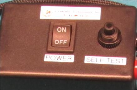
2 TABLE OF FIGURES

Figure 1 SDK Power Control/Self-Test, SDK to PC Cabling ............................................................................ 2
Figure 2 Unit Connector ................................................................................................................................ 3
Figure 3 Read Me First Installation Guide..................................................................................................... 3
Figure 4 SDK Installation Disc ........................................................................................................................ 4
Figure 5 Files on Installation Disc .................................................................................................................. 5
Figure 6 Driver Setup Wizard ........................................................................................................................ 5
Figure 7 License Agreement Prompt............................................................................................................. 6
Figure 8 Installation Folder Prompt .............................................................................................................. 6
Figure 9 Driver Package Information Prompt ............................................................................................... 7
Figure 10 Driver Installation Status............................................................................................................... 7
Figure 11 Glamr Location on SDK CD-ROM................................................................................................... 8
Figure 12 Glamr Shortcut Software Icon....................................................................................................... 8
Figure 13 Glamr Screen before Selecting Correct COM Port Settings .......................................................... 9
Figure 14 Confirmed Correct LINX Port with Message "success" ............................................................... 10
Figure 15 Baud Rate Selection for 1000 Hz Data Rate ................................................................................ 11
Figure 16 Gyro Data at 1000 Hz Data Rate ................................................................................................. 12
Figure 17 Mode Selection / Data Rate ........................................................................................................ 12
Figure 18 IMU Mode at 500 Hz Data Rate .................................................................................................. 13
Figure 19 Power and Self-Test Momentary Switch..................................................................................... 14
Figure 20 Self-Test Display when Activated ................................................................................................ 14
Figure 21 Gyro Units of Measure Selection Options................................................................................... 15
Figure 22 Data Record Capability ................................................................................................................ 16
Figure 23 Start Record File Path.................................................................................................................. 17
Figure 24 Saving Data Record Time ............................................................................................................ 18
Figure 25 Select Desired Bandwidth Filter from Drop-Down Menu ........................................................... 19
Figure 26 Message Options for Troubleshooting ....................................................................................... 20
Figure 27 G400D Biaxial Digital Gyro 3D Model ......................................................................................... 24
Figure 28A Standard G400D Biaxial Digital Gyro Outline Drawing ............................................................. 26

G400D™ Biaxial Gyro User’s Guide                                  Page iii                                               Rev. 2/05/2018
Copyright © 2015-2018 Gladiator Technologies

Figure 29 Axis Orientation .......................................................................................................................... 27
Figure 30 G400D Biaxial Digital Gyro Exploded Outline Drawing (metric in [mm]).................................... 27
Figure 31 G400D Biaxial Digital Gyro Block Diagram .................................................................................. 29
Figure 32 Gladiator Technologies Part Naming Convention....................................................................... 30
Figure 33 G400D Biaxial Digital Gyro Part Number Configurations ............................................................ 30
Figure 34 G400D-250-100 Biaxial Digital Gyro Pin Assignments and Outputs ........................................... 31
Figure 35 Serial Communication Settings ................................................................................................... 32
Figure 36 Screenshot of G400D Biaxial Digital Gyro Sample Data .............................................................. 33
Figure 37 2.5 kHz Timing Diagram .............................................................................................................. 34
Figure 38 Bandwidth Frequency and Output Data Rate ............................................................................. 35
Figure 39 Gyro Bandwidth vs. Peak-to-Peak Noise 100 Hz ......................................................................... 36
Figure 40 Gyro Bandwidth vs. Peak-to-Peak Noise 1 kHz ........................................................................... 36
Figure 41 Rate Spin Test.............................................................................................................................. 37
Figure 42 1g Tumble Test Data ................................................................................................................... 38
Figure 43 Angle Random Walk .................................................................................................................... 39
Figure 44 Gyroscope Allan Deviation .......................................................................................................... 40
Figure 45 X Gyro Bias In-Run ....................................................................................................................... 41
Figure 46 Y Gyro Bias In-Run ....................................................................................................................... 42
Figure 47 X Gyro Bias over Temperature .................................................................................................... 43
Figure 48 Y Gyro Bias over Temperature .................................................................................................... 44
Figure 49 X Gyro Scale Factor over Temperature ....................................................................................... 45
Figure 50 Y Gyro Scale Factor over Temperature ....................................................................................... 46
Figure 51 X Gyro Bias Turn-On .................................................................................................................... 47
Figure 52 Y Gyro Bias Turn-On .................................................................................................................... 48
Figure 53 Random Vibration Test Data ....................................................................................................... 49
Figure 54 X and Y Gyro Sine Vibration Response ........................................................................................ 50
Figure 55 Website – Select Product Category ............................................................................................ 52

G400D™ Biaxial Gyro User’s Guide                                  Page iv                                               Rev. 2/05/2018
Copyright © 2015-2018 Gladiator Technologies
3 SAFETY AND HANDLING INFORMATION
• Always use caution when handling the G400D Biaxial Digital Gyro!
• Supplying too high an input voltage could permanently damage the unit. Input Power is
specified at +3.8 V to +5.5 V Maximum. The unit is specified at 5 V ± 0.3 V.
• The G400D Biaxial Digital Gyro is a sensitive scientific instrument containing shock and vibration
sensitive inertial and other sensors. Excessive shock and or vibration can damage these sensors
and can adversely affect sensor performance and unit output.
• Avoid exposure to electrostatic discharge (ESD). Observe proper grounding whenever handling
the G400D Biaxial Digital Gyro.
• Properly attach connector and ensure that it has been wired correctly before applying power
to the G400D Biaxial Digital Gyro.
4 GETTING STARTED
This section contains directions and references for a quick start to using the G400D.
For additional support, please contact the distributor representing your location. If there isn't a local
representative for your location, please contact our Headquarter office for assistance and someone
from our Sales Team will assist you.
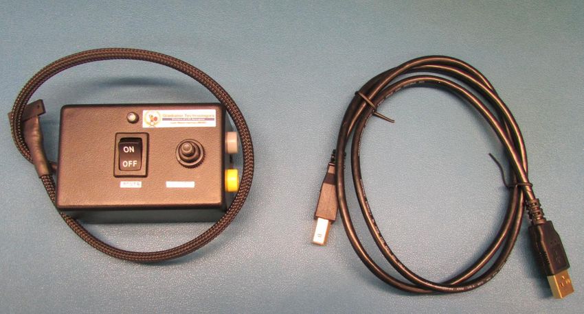
The G400D Biaxial Digital Gyro Software Development Kit (SDK) is an optional product to assist first-time
users of the G400D Biaxial Digital Gyro. This kit provides the user everything they need to facilitate a
rapid setup and test of the unit. The SDK (P/N SDK-IMU-8) includes display software with user defined
options including the following components and is seen in Figure 1:
• Turn-Key Solution for G400D Biaxial Digital Gyro on User PC
• All Cabling, Interface Connectors, and Software Included and Ready for Use
• Easy Integration of Direct Gyro RS-422/RS485 to PC’s USB Port
• Includes PC Display Software for Gyro
• Data Recording Capability
• Multiple User Selected Field Options for Programming and Initializing the Unit
• User Defined Bandwidth Settings and Data Output Rate on Gyro
• Self-Test Switch
• External Sync
G400D™ Biaxial Gyro User’s Guide Page 1 Rev. 2/05/2018
Copyright © 2015-2018 Gladiator Technologies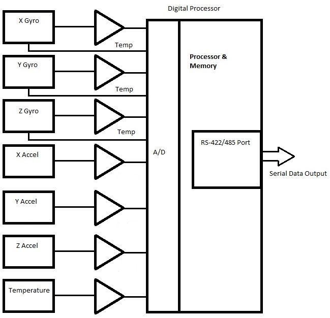
Figure 1 SDK Power Control/Self-Test, SDK to PC Cabling

The following steps will allow the user to quickly set up a G400D and interface it with its SDK.

    1. Connect all units together per the User Guide under this section (Getting Started) to the PC. Do
       not turn on the power yet. Follow all steps in Section 4 carefully.
    2. Follow the instructions from the enclosed disc under Linx SW labeled “STOP! Read This First -
       Installation Guide” to load the VCP drivers for the USB interface.
    3. Copy the Glamr.msi software and setup.exe applications to the PC hard drive from the header
       file on the disc.
    4. Run the Glamr.msi to install the Glamr and select the com port to LINX if not selected.
    5. Apply power to the unit to see data on the screen. Turn the self-test switch to ON to see a
       change in the sensor data that ensures the unit is functioning. Then switch OFF.
    6. Follow the instructions in the following sections of the User Guide Glamr Software Installation
       (Section 4.5) to change any factory settings for your application.

G400D™ Biaxial Gyro User’s Guide               Page 2                                     Rev. 2/05/2018
Copyright © 2015-2018 Gladiator Technologies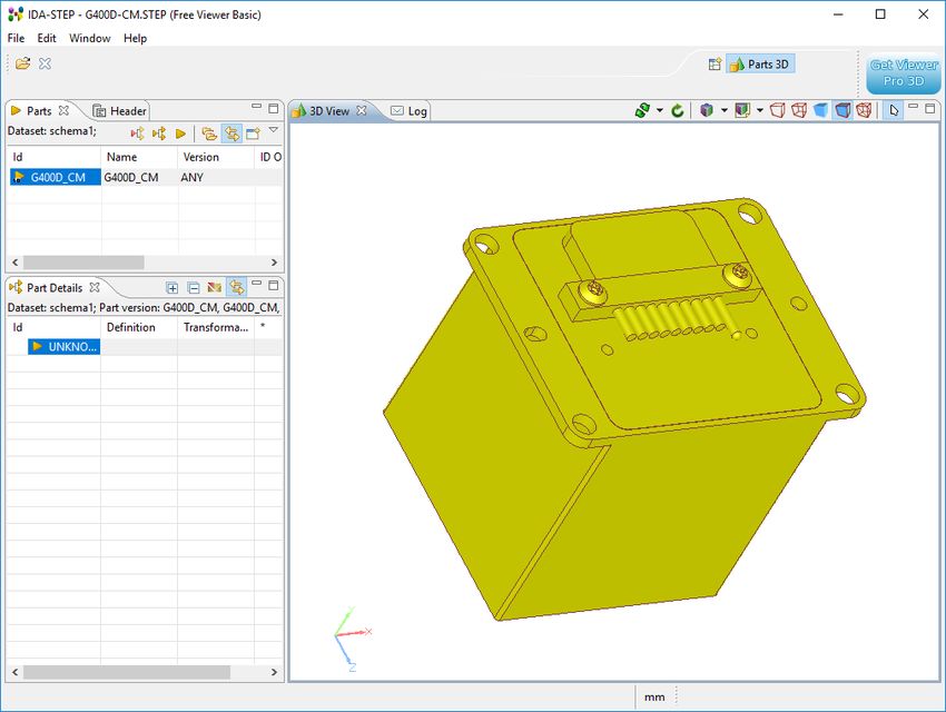
4.1 RS-422/RS485 to USB Power Supply & Converter Cable
Contained in the Software Development Kit (SDK) is a complete RS-422/RS485 to USB Converter cable
including power supply and self-test switch (Fig. 1). The power supply uses USB power.

An RS-422/RS485 to USB converter is also included (requires additional drivers that are included in the
CD-ROM).

This power supply converter cable enables the user to quickly connect the G400D Biaxial Digital Gyro to
their PC to ease integration and testing. Connect the cables to the unit and the converter board to the
PC with the USB cable. Do not turn on the power switch until the rest of the software is installed.

                                               Figure 2 Unit Connector

4.2 G400D Biaxial Digital Gyro Mating Connector
The G400D Biaxial Digital Gyro mating connector and mating pins are contained in a separate package to
enable customer-specific wiring options. If the SDK was purchased, then the customer also has an RS-
422/RS485 Converter board, USB connector, and mating pins.

4.3 STOP! Read This First

                  You must first install the USB drivers from the enclosed USB
                  Driver CD-ROM before using Glamr to read the unit. Look on the
                  CD-ROM under Linx SW and perform the instructions in the PDF
                  “Read Me First - Installation Guide” (Figure 5).

                  Note: This driver is designed for Windows programs only.

                                      Figure 3 Read Me First Installation Guide

G400D™ Biaxial Gyro User’s Guide               Page 3                              Rev. 2/05/2018
Copyright © 2015-2018 Gladiator Technologies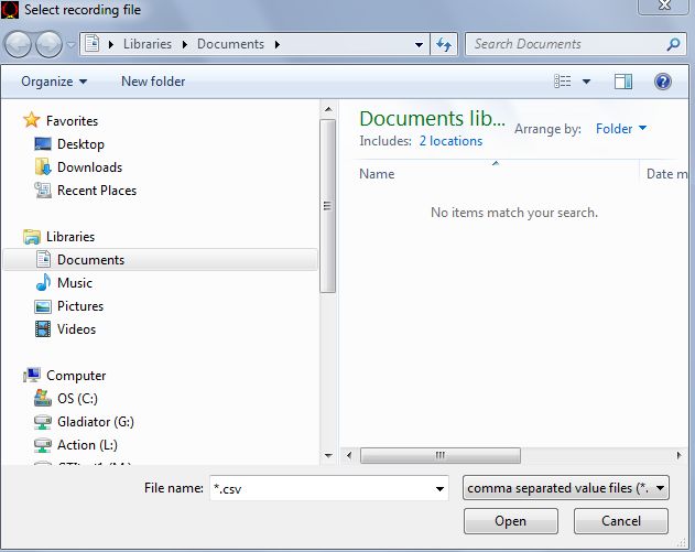
4.4 Installing the LINX SDM-USB-QS-S Drivers SIMPLE

4.4.1 Introduction
The LINX SDM-USB-QS-S module requires that device drivers be
installed on the host PC before they can interact. The drivers tell
the PC how to talk to the module. These drivers are for Windows
98, XP, NT, Windows 7, and Windows 8. For Windows 10
installation, please see the note. The set for Windows are the direct
drivers, which offer program functions that allow a custom
application to directly control the module through the USB
port.                                                                       Figure 4 SDK Installation Disc

 NOTE: This is for the installation on machines running the Windows 10 Operating System.

 1. Install LINX driver first. This is updated for Windows 10 and is found here:

 https://linxtechnologies.com/wp/wp-content/uploads/qs_driver_installer.zip

 Do NOT use the FTDI device driver that Windows 10 provides. It does not work with the LINX product
 even though they are using the FTDI parts. The PID was changed so it is unique.

 2. When installing Glamr, there will be an error message saying “Combined.OCX could not be
 registered.” This is due to missing some DLLs. To get these dependencies, you need to install a
 Microsoft Redistribution package. This package (language dependent for our foreign customers) can
 be found at:

 https://www.microsoft.com/en-us/download/details.aspx?id=29

G400D™ Biaxial Gyro User’s Guide               Page 4                               Rev. 2/05/2018
Copyright © 2015-2018 Gladiator Technologies
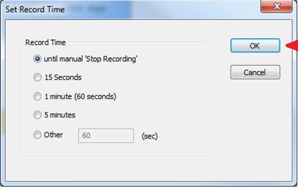
Figure 5 shows which files will be available to the user via the SDK Installation Disc. Test data and a User
Guide for the unit are also included. If multiple units are purchased, the respective User Guides for each
different product will be located on the disc. The most recent revision of this guide will be available
from the product page on the Gladiator website.

                                           Figure 5 Files on Installation Disc

4.4.2 Installing the Direct Drivers
The drivers are included in the Linx SW folder and should be saved onto the hard drive of a PC or onto a
flash drive. Double click on the QS_Driver_Installer.msi for the Setup Wizard.

                                                   Click Next

                                               Figure 6 Driver Setup Wizard

                                  Read License, click I Agree, then Next

G400D™ Biaxial Gyro User’s Guide                 Page 5                              Rev. 2/05/2018
Copyright © 2015-2018 Gladiator Technologies
Figure 7 License Agreement Prompt
Click Next upon arrival at the Installation Folder prompt
Figure 8 Installation Folder Prompt
Click Next at the Driver Package Information prompt
G400D™ Biaxial Gyro User’s Guide Page 6 Rev. 2/05/2018
Copyright © 2015-2018 Gladiator Technologies● Windows 8
Figure 9 Driver Package Information Prompt
NOTE: Plug the connector cable into the USB port before you turn the device power on to avoid
Windows loading as a mouse driver.
Allow driver installation to complete
Figure 10 Driver Installation Status
G400D™ Biaxial Gyro User’s Guide Page 7 Rev. 2/05/2018
Copyright © 2015-2018 Gladiator Technologies4.5 Glamr Software Installation
Now install the Glamr application off of the CD-ROM. Open the Glamr file (Fig. 11) in the enclosed CD-
ROM and install the application to the desired location on the hard drive. Note that the Glamr display
has common software features for IMUs and Gyro Biax units.
Figure 11 Glamr Location on SDK CD-ROM
Once Glamr is installed, create a shortcut on your desktop to the application. Right click on the Glamr
Software icon on your hard drive file. Select create shortcut. Drag this shortcut file and drop on your
desktop, as seen in Figure 12.
Figure 12 Glamr Shortcut Software Icon
G400D™ Biaxial Gyro User’s Guide Page 8 Rev. 2/05/2018
Copyright © 2015-2018 Gladiator TechnologiesOpen the Glamr software and a window will appear as in Figure 13.
Figure 13 Glamr Screen before Selecting Correct COM Port Settings
The bottom of the Gladiator Gyro Display may read “IMU serial port (LINX SDM-USB, 115200, 8E1)
ERROR opening.”
Only one copy of Glamr can be open at a given time. Always make sure there is not another copy open
on the task bar. If there are multiple copies of Glamr open, a message will appear at the bottom of the
Gyro Display window.
G400D™ Biaxial Gyro User’s Guide Page 9 Rev. 2/05/2018
Copyright © 2015-2018 Gladiator TechnologiesReconnect the USB plug to the SDK. The “LINX” port should have a checkmark next to it. The bottom of
the window should now read “IMU serial port (LINX SDM-USB, 115200, 8E1) success”, as shown in
Figure 14.
Figure 14 Confirmed Correct LINX Port with Message "success"
Turn on the power switch located on the SDK and data should appear in the window as seen in Figure 15
(blue box). Movement of the Gyro will see changes in rate and acceleration for each axis located within
the Gyro. These changes are reflected on-screen. To see rapid change, the record function will capture
real time data without the filter effect on the screen.
G400D™ Biaxial Gyro User’s Guide Page 10 Rev. 2/05/2018
Copyright © 2015-2018 Gladiator Technologies4.6 Select Applicable Baud Rate
Baud Rate →
Data Rate 115200 921600 1.5 M 3.0 M Bits/second
↓ 100 Yes Yes Yes Yes 19800
200 Yes Yes Yes Yes 39600
500 * Yes Yes Yes 99000
1000 Yes Yes Yes 198000
2500 Yes Yes Yes 495000
5000 Yes Yes 990000
6000 Yes Yes 1188000
Note that the 500 Hz Data Mode is a special case. Please refer to Section 4.7.1 for more details.
Figure 15 Baud Rate Selection for 1000 Hz Data Rate
G400D™ Biaxial Gyro User’s Guide Page 11 Rev. 2/05/2018
Copyright © 2015-2018 Gladiator TechnologiesFigure 16 Gyro Data at 1000 Hz Data Rate
The message “Msg out-of-sequence: exp 0, act 96” may sometimes appear and indicates that the
program saw a skip in the message count. This case will happen at start-up and can be ignored.
4.7 Setting the Mode and Data Rate
The SDK software also has data rate adjustment and data set selection. This feature is selected under
Mode as shown in Figure 17. This allows a reduced data set in Spec mode.
Figure 17 Mode Selection / Data Rate
G400D™ Biaxial Gyro User’s Guide Page 12 Rev. 2/05/2018
Copyright © 2015-2018 Gladiator Technologies4.7.1 Set IMU Mode 500 Hz Data Rate
All Gyros can be put into a 500 Hz data rate mode. This can be seen in Figure 18.
NOTE: To reset to another mode once in 500 Hz data rate mode, the unit requires a special procedure
if at 115,200 baud rate.
Reverting the unit back to any other mode requires a mode click to the desired rate. This will
command the unit to wait for a power recycle as per the screen instructions. To set the unit to the
new mode upon powering up, turn on power and the new data rate will be shown under the green
bar in the center-left “xxx msgs per sec.”
Figure 18 IMU Mode at 500 Hz Data Rate
G400D™ Biaxial Gyro User’s Guide Page 13 Rev. 2/05/2018
Copyright © 2015-2018 Gladiator Technologies4.8 Self-Test in Glamr
Glamr includes a self-test function. The user can initiate the self-test by the momentary switch (Fig. 19),
contained within the switch box that is included in the G400D Biaxial Gyro SDK.
Press the switch button to activate self-test of the sensors. The Glamr display will now show “SELF-TEST”
is activated while also showing the data outputs. This message is located just above the data rate status
bar. You should see a delta change in the X and Y sensor outputs when you initiate self-test per the data
sheet (Fig. 20).
Figure 19 Power and Self-Test Momentary Switch
Figure 20 Self-Test Display when Activated
G400D™ Biaxial Gyro User’s Guide Page 14 Rev. 2/05/2018
Copyright © 2015-2018 Gladiator Technologies4.9 Unit Display Options
The SDK software can also set the dimensional units of the display. This is selected under Units, as seen
in Figure 21.
Figure 21 Gyro Units of Measure Selection Options
G400D™ Biaxial Gyro User’s Guide Page 15 Rev. 2/05/2018
Copyright © 2015-2018 Gladiator Technologies4.10 Data Record Feature
The SDK software also has a data record feature that captures data outputting from the Gyro and puts it
into .csv format. This enables the user to easily convert these data files to Excel or database format. The
user should click the Start Recording button (Fig. 22) to initiate the data record function. When they
wish to stop recording, simply click the Stop Recording button.
Figure 22 Data Record Capability
G400D™ Biaxial Gyro User’s Guide Page 16 Rev. 2/05/2018
Copyright © 2015-2018 Gladiator TechnologiesSelect “Start Record” and designate the file name and location before the recording begins. To begin
Data Record function, click on Open as per Figure 23. After the designated file is established, click the
desired length of time to record then click OK (Fig. 24).
Click on Open
to start
recording.
Figure 23 Start Record File Path
NOTE: Be sure to look at the Glamr message log to ensure file path is correct and file has successfully been
opened for writing.
G400D™ Biaxial Gyro User’s Guide Page 17 Rev. 2/05/2018
Copyright © 2015-2018 Gladiator TechnologiesClick OK to
start recording
Figure 24 Saving Data Record Time
4.11 Bandwidth Filtering Capability
Bandwidth vs. Noise
The user should be aware that the standard G400D Biaxial Digital Gyro is optimized for high bandwidth,
so the gyro bandwidth is set at 250 Hz. True bandwidth with the -3 dB point is approximately 250 Hz
when the 2.5 kHz sample system is included. These are the settings for the standard unit when shipped
and the noise may not be optimized for an end-user’s specific application. The high bandwidth is ideal
for dynamic applications where the high bandwidth would be required to close control loops in flight
control in a UAV, for example. However, in UAV navigation, a lower bandwidth would be possible and
there would be an improvement in noise. Laboratory uses, automotive monitoring, or stabilization
applications would likely prefer improved noise and could tolerate reduced bandwidth.
G400D™ Biaxial Gyro User’s Guide Page 18 Rev. 2/05/2018
Copyright © 2015-2018 Gladiator TechnologiesEffective with G400D Biaxial Digital Gyro SDK, Gladiator Technologies offers the end-user the capability
to set bandwidth filtering in permanent memory. This enables the end-user to set lower bandwidth
levels than 250 Hz and benefit from the reduced peak-to-peak noise of the sensors in the G400D Biaxial
Digital Gyro. To utilize this capability, select Load from the drop down menu as seen in Figure 25.
Select desired
bandwidth
Figure 25 Select Desired Bandwidth Filter from Drop-Down Menu
Next select the desired true bandwidth of the gyros with the software filter. The user can select from
Maximum (this is the full sensor bandwidth and standard units are shipped with this setting) or from the
other bandwidth options all the way down to 1 Hz. Once this is set and the user takes and confirms data
with this new setting, the G400D Biaxial Digital Gyro bandwidth filter setting will remain at the setting
until the user changes it in the same manner as detailed in this section.
G400D™ Biaxial Gyro User’s Guide Page 19 Rev. 2/05/2018
Copyright © 2015-2018 Gladiator TechnologiesTo help with troubleshooting, users can change what is displayed in the message section of Glamr. This
is accessed through the View tab as shown in Figure 26.
Message
section
Figure 26 Message Options for Troubleshooting
5 PATENT AND TRADEMARK INFORMATION
The G400D Biaxial Digital Gyro is a newly developed unit containing significant intellectual property and
is expected to be protected by United States of America (USA) and other foreign patents pending.
LandMark™ is an official and registered Trademark that identifies the Gladiator Technologies brand name
for our digital inertial and integrated GPS systems products.
G400D™ Biaxial Gyro User’s Guide Page 20 Rev. 2/05/2018
Copyright © 2015-2018 Gladiator Technologies6 APPLICABLE EXPORT CONTROLS The G400D Biaxial Digital Gyro has been self-classified by Gladiator Technologies with pending Commodity Classification by the U.S. Department of Commerce under the Export Administration Regulations (EAR), as ECCN7A994 and as such may be exported without a license using symbol NLR (No License Required) to destinations other than those identified in country group E of supplement 1 to Part 740 (commonly referred to as the T-5 countries) of the Export Administration Regulations. Items otherwise eligible for export under NLR may require a license if the exporter knows or is informed that the items will be used in prohibited chemical, biological, or nuclear weapons or missile activities as defined in Part 774 of the EAR. Copies of official U.S. Department of Commerce Commodity Classifications are available upon request. 7 USER LICENSE Gladiator Technologies grants purchasers and/or consignees of Gladiator’s G400D Biaxial Digital Gyro a no cost, royalty-free license for use of the following software code for use with the G400D Biaxial Digital Gyro. Companies or persons not meeting the criteria as a purchaser or consignee are strictly prohibited from use of this code. Users in this category wanting to use the code may contact the factory for other user licensing options. 8 STANDARD LIMITED WARRANTY Gladiator Technologies offers a standard one (1) year limited warranty with the factory’s option to either repair or replace any units found to be defective during the warranty period. Opening the case, mishandling, or damaging the unit will void the warranty. Please see Gladiator Technologies’ Terms and Conditions of sale regarding specific warranty information. 9 QUALITY MANAGEMENT SYSTEM Gladiator Technologies’ Quality Management System (QMS) is certified to AS9100 Rev. C and ISO9001:2008. UL DQS is the company’s registrar and our certification number is 10012334 ASH09-1. Please visit our website at www.gladiatortechnologies.com to view our current certificates. G400D™ Biaxial Gyro User’s Guide Page 21 Rev. 2/05/2018 Copyright © 2015-2018 Gladiator Technologies
10 THEORY OF OPERATION
The G400D Biaxial Digital Gyro is a digital two Degree of Freedom MEMS (Micro Electro-Mechanical
System) IMU that provides delta theta information, as well as temperature. Utilizing Gladiator
Technologies’ proprietary thermal modeling process, this unit is fully temperature compensated, with
temperature-corrected bias and scale factor, plus corrected misalignment and g-sensitivity.

The unit features:

    •   The RS-422/RS485 serial digital interface provides serial data outputs and enables the user to
        monitor the outputs during use. Internal sampling is done at 8 kHz. Oversampling is done on the
        Gyro output rate (2X) when set at 2.5 kHz and then averaged to improve the noise of the MEMS
        sensors. The nominal output rate in the G400D Biaxial Digital Gyro is 2.5 kHz ± 5%. An RS-
        422/RS485 to USB converter is available in Gladiator's G400D Biaxial Digital Gyro Software
        Development Kit (SDK) to enable quick G400D to PC integration and ease of use.
    •   Three MEMS gyro signals with active filtering and 2X oversampled when set at 2.5 kHz with a 16-
        bit A/D converter. The gyros are available in standard ranges of ± 250°/sec or ± 490°/sec.
    •   Two internal temperature sensor outputs are 2X oversampled when set at 2.5 kHz with a 16-bit
        converter. These temperature measurements are co-located with the x- and y-axis gyros to
        enable accurate temperature compensation of the gyro outputs.
    •   The calibration process measures temperature set points in five degree increments, from -40°C
        to +85°C. Then, a nine-point correction table is generated that identifies temperature based
        offsets for each of the gyro data sets. Depending upon the variable, up to a 4th order thermal
        model is used to create a correction model.
    •   Though a precision orthogonal mounting block is used in the G400D Biaxial Digital Gyro,
        misalignment error correction is also essential in enabling high performance navigation from a
        MEMS inertial sensor assembly. The calibration process also corrects and compensates for
        internal misalignment errors for all sensors in all three axes.
    •   In addition, "g-sensitivity" errors associated with the gyros are also modeled and calibrated to
        correct these performance errors associated with acceleration inputs in all three gyro axes.
    •   All of the calibration data is then loaded into an internal memory EEPROM enabling a look-up
        table for thermal modeling correction of the outputs during use.

The G400D Digital Biax MEMS Gyro data sheet is available to our gyro customers via download on our
website. For more information please see Gladiator Technologies’ website at
www.gladiatortechnologies.com. Copies of product User’s Guides are available upon request at
support@gladiatortechnologies.com

G400D™ Biaxial Gyro User’s Guide             Page 22                                Rev. 2/05/2018
Copyright © 2015-2018 Gladiator Technologies
11 G400D BIAXIAL DIGITAL GYRO PRODUCT DESCRIPTION
The G400D Biaxial Digital Gyro is our digital output biaxial gyro model featuring our lowest noise MEMS
gyros that also offer outstanding bias in-run and bias over temperature. This high-performance MEMS
Biaxial Gyro provides internally temperature-compensated RS-422/RS485 output of delta thetas.
Designed for commercial stabilization and aircraft applications, the G400D Biaxial Digital Gyro is ideal for
commercial applications requiring high inertial performance approaching “small RLG or open loop FOG-
Class,” yet available at much lower cost. Other key advantages include low power consumption, small
size, light weight and no inherent wear out modes for long life. The signature features of the G400D
Biaxial Digital Gyro are the exceptionally low noise and bias performance.
• Non-ITAR MEMS Digital Biaxial Gyro (1” Cube)
• Low Noise < 0.0028/sec/Hz
• Wide Sensor Bandwidth 250 Hz, Low Latency
• Gyro Bias In-Run 5°/hour 1σ
• Bias Over Temperature ≤ 0.05°/sec 1σ
• Compensated Misalignment ≤ 0.5 mrad 1σ
• G-Sensitivity ≤ 0.001°/sec/g 1σ
• Full Temperature Calibration (Bias and SF)
• Vibration 8grms
• Shock Resistant 600g
• Light Weight ≤ 40 grams
• Ultra-Low Power < 300 mW typical
• RS-422/485 Serial Data up to 3 Mbaud (selectable)
• Low Voltage +3.8 V to +5.5 V
• External Sync Input up to 5 kHz
The G400D’s ultra-low noise and low bias MEMS gyros enable precision measurement including
excellent in-run bias and bias over temperature. The gyro’s performance is optimized with fully
temperature compensated bias and scale factor, as well as compensated misalignment and g-sensitivity.
The unit is environmentally sealed in a rugged enclosure and has a MIL-SPEC connector in order to
withstand environmental vibration and shock typically associated with commercial aircraft
requirements. The G400D Biaxial Digital Gyro is well suited for demanding commercial applications
including: precision imaging, platform and antenna stabilization, rail track telemetry, navigation, flight
control, flight testing, and laboratory use. Other standard custom ranges are available.
G400D™ Biaxial Gyro User’s Guide Page 23 Rev. 2/05/2018
Copyright © 2015-2018 Gladiator Technologies11.1 Outline Drawing and 3D Solid Models
Please go to the applicable product of interest on our website at www.gladiatortechnologies.com and
download the 3D Solid Model, 2D outline drawing, and other product information.
11.1.1 3D Solid Model
Figure 27 shows the G400D Biaxial Gyro in a 3D environment.
Figure 27 G400D Biaxial Digital Gyro 3D Model
G400D™ Biaxial Gyro User’s Guide Page 24 Rev. 2/05/2018
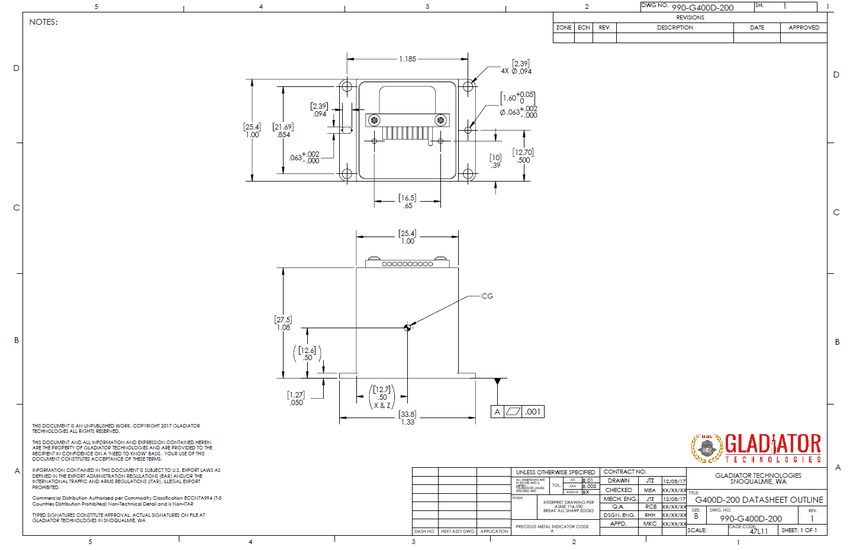
Copyright © 2015-2018 Gladiator Technologies11.1.2 Outline Drawing
Figure 28 G400D Biaxial Digital Gyro Outline Drawing with Top Mount
G400D™ Biaxial Gyro User’s Guide Page 25 Rev. 2/05/2018
Copyright © 2015-2018 Gladiator TechnologiesFigure 28A Standard G400D Biaxial Digital Gyro Outline Drawing G400D™ Biaxial Gyro User’s Guide Page 26 Rev. 2/05/2018 Copyright © 2015-2018 Gladiator Technologies
11.2 Outline Exploded View & Axis Orientation

 Figure 29 Axis Orientation

                     Figure 30 G400D Biaxial Digital Gyro Exploded Outline Drawing (metric in [mm])

G400D™ Biaxial Gyro User’s Guide             Page 27                                    Rev. 2/05/2018
Copyright © 2015-2018 Gladiator Technologies
11.3 Center of Gravity
Some applications need to know the CG (center of gravity) of the package, which is simply the mass
center. The CG is near the center line of the package, located at the midpoint along the z-axis above the
base plate and with the following offsets:
• X offset = 0 inches (0 mm) along the centerline
• Y offset = 0 inches (0 mm) along the centerline
• Z offset = +0.52 inches (13.1 mm) above the case mounting plane
G400D™ Biaxial Gyro User’s Guide Page 28 Rev. 2/05/2018
Copyright © 2015-2018 Gladiator Technologies11.4 G400D Biaxial Digital MEMS Gyro Block Diagram
Figure 31 G400D Biaxial Digital Gyro Block Diagram
G400D™ Biaxial Gyro User’s Guide Page 29 Rev. 2/05/2018
Copyright © 2015-2018 Gladiator Technologies11.5 G400D Biaxial Digital Gyro Part Naming Convention & Part Numbers
G400D-250-100
G400 D 250 100
Product Make Product Gyro Rate Specific Unit
“Gyro” Model Range Configuration
“Digital” “250°/sec” “100” (Biax)
Figure 32 Gladiator Technologies Part Naming Convention
G400D Digital Gyro
G400D-250-100 Biax 250°/sec
G400D-490-100 Biax 490°/sec
Figure 33 G400D Biaxial Digital Gyro Part Number Configurations
G400D™ Biaxial Gyro User’s Guide Page 30 Rev. 2/05/2018
Copyright © 2015-2018 Gladiator Technologies11.6 G400D Biaxial Digital Gyro Pin Assignments
The G400D Biaxial Digital Gyro has a nine pin MIL-SPEC connector interface which provides the electrical
interface to the host application.
11.6.1 G400D-100
Pin No. Assignment
1 RS-422/485 A (+) (Twisted Pair)
2 RS-422/485 B (-) (Twisted Pair)
3 Power Ground
4 Not Connected
5 +3.8 V to +5.5 V Max Input Power
6 External Sync A Input (up to 5 kHz)
7 Signal Ground
8 External Sync B Input
9 Case
Outputs Serial Sequence at 2.5kHz
1 Roll Gyro (X)
2 Pitch Gyro (Y)
3 Temperature ± 0.5º C typical
Figure 34 G400D-250-100 Biaxial Digital Gyro Pin Assignments and Outputs
NOTE: If the input pins have long wires with no termination, they can pick up noise in a high EMI
environment and upset the proper operation of the Gyro. Pin 4 is particularly vulnerable to noise
pickup and can cause data drops and is OK if connected to a logic level 5 kHz signal source, otherwise
connect to Pin 8.
11.7 G400D Biaxial Digital Gyro Performance Specification
See applicable current revision data sheet available on our website at www.gladiatortechnologies.com.
G400D™ Biaxial Gyro User’s Guide Page 31 Rev. 2/05/2018
Copyright © 2015-2018 Gladiator Technologies12 G400D Biaxial Digital Gyro MESSAGE PROTOCOL (≥ V72)
12.1 Serial Communication Settings
Parameter Value
Bits/second: 115200, 921600, 1.5 Mbit, 3.0 Mbit
Data bits: 8
Parity: E
Stop bits: 1
Figure 35 Serial Communication Settings
12.2 Biaxial Gyro Message Packet Format
At power-up, the Gyro enters operational mode using the last commanded mode setting. Please refer
to the Gladiator Technologies Software Reference for additional information.
G400D™ Biaxial Gyro User’s Guide Page 32 Rev. 2/05/2018
Copyright © 2015-2018 Gladiator Technologies12.3 Sample Data Format
Figure 36 provides a sample Gyro data output in Excel. The real output includes both the header
information and data (see rows with MSGCOUNT) that contain actual output data. Also included are the
multiplier information, averages, and units of measure for additional clarity for the user. The Gyro
Software Development Kit also includes the actual Excel file as in Figure 36, so that the user can quickly
identify the formulas to use in their system integration directly from the sample data file.
MSGCOUNT GYRX (°/s) GYRY (°/s) TEMPX (C)
106 -0.153 -0.023 23.53
107 -0.023 -0.137 23.49
108 -0.023 -0.038 23.54
109 -0.153 -0.061 23.56
110 -0.008 -0.107 23.55
111 -0.076 -0.031 23.54
112 -0.183 -0.046 23.51
113 0 -0.076 23.47
114 -0.122 0.015 23.5
115 -0.168 -0.023 23.5
116 -0.038 -0.076 23.5
117 -0.061 -0.053 23.54
118 -0.13 0 23.55
119 0.053 -0.107 23.55
120 -0.122 -0.076 23.55
121 -0.107 -0.084 23.55
122 0 -0.015 23.53
123 -0.168 -0.046 23.53
124 -0.107 -0.046 23.54
125 0 -0.069 23.58
Figure 36 Screenshot of G400D Biaxial Digital Gyro Sample Data
Please note that when a customer uses the Glamr interface it automatically rescales the gyros. This is
displayed in Figure 36, as well as the sample Excel file included in the G400D Biaxial Digital Gyro
Software Development Kit (SDK). However, if the user is not using Glamr and inputting directly into their
system then they should use the LSB’s noted above (LSB 0.00763°/sec for 250°/sec rate range gyros and
0.01 degrees for temperature).
G400D™ Biaxial Gyro User’s Guide Page 33 Rev. 2/05/2018
Copyright © 2015-2018 Gladiator Technologies12.4 Sync Input (2.5 kHz)
The optional input to the Gyro is a sync square wave to Pin 6. This allows the data stream to be
synchronized to an external clock. For example, if the user wants to supply and sync an external GPS to
the Gyro, the GPS can generate a 2.5 kHz square wave which is sent to the Gyro when the GPS signal is
valid. However, any external 2.5 kHz clock of logic level can be used to synchronize the data.
12.4.1 Specification
• Clock 2.5 kHz ± 5% square wave (40 - 60 duty cycle not critical)
• Data sample starts on rising edge only
• 3.3 V logic is suggested (-0.3 V < “0” < 0.8 V and 2.0 V < “1” < 5.3 V) with respect to signal ground
• Input has diode protection for levels below -0.7 V or above 5.5 V to 10.5 V to protect the CPU,
but excessive levels may cause performance problems
12.4.2 Status Bit
The Gyro will operate on an internal 5 kHz clock (which is internally counted down to 2.5 kHz for output)
until an external clock is detected. Then the Gyro will automatically switch over and set Status Bit 1 to
true. It should be noted that as the internal and external clocks are asynchronous, the first transition to
Ext Sync will take a few clock periods to align. The Status Bit will be set true for that period even if there
is only one sample. However, the next data package will all be samples on the external clock. Refer to
the timing diagram to see the relationship between external clock and data transmission (Fig. 37). The
Gyro will revert to the internal clock if the external clock is removed.
12.4.3 Timing Diagram
G400D - 55.4.72.3 Internal Sync
Timing (2.5kHz) 0.2 msec 0.4 msec 0.6 msec 0.8 msec 1.0 msec 1.2 msec 1.4 msec 1.6 msec 1.8 msec 2.0 msec
Data Reads GYROS GYROS GYROS GYROS GYROS
Processor samples 1
Average delay Gyro 0µs±62.5µs
Processor Starts Samples
Process Ends 70µs Repeat
Transmission Starts
1.535M baud Ends 68µs
Total Delay Gyro 97µs±62.5µs = 200.5 µsec max
Degrees at 2500Hz = Gyro 360*0.2005/0.4= 180.45 degrees
Degrees at 50 Hz = Gyro 180.45/50= 3.6 degrees
250Hz Single Pole 11.3 degrees
349Hz Single Pole 8.2 degrees
N=3 Gyro
Total Degrees at 50Hz 14.9 degrees
Figure 37 2.5 kHz Timing Diagram
G400D™ Biaxial Gyro User’s Guide Page 34 Rev. 2/05/2018
Copyright © 2015-2018 Gladiator Technologies12.5 Bandwidth vs. Noise
Note that our standard G400D Biaxial Digital Gyro is optimized for high bandwidth, so the gyros are set
at 200 Hz. True bandwidth includes the data sampling effects and has the -3 dB point, which is
approximately half of the sample frequency. These are the settings for the standard unit when shipped
and the noise may not be optimized for an end-user’s specific application. The high bandwidth is ideal
for dynamic applications where the high bandwidth would be required to close control loops in flight
control in a UAV, for example. However, in UAV navigation, a lower bandwidth would be possible and
the unit would output an improvement in peak-to-peak noise. Laboratory uses, automotive monitoring,
or stabilization applications would likely prefer improved (lower) noise and could tolerate reduced
bandwidth.
The G400D Biaxial Digital Gyro Software Development Kit offers the end-user the ability to set
bandwidth filtering in permanent memory. This enables the end-user to set lower bandwidth levels than
the sensor bandwidth in order to benefit from the reduced peak-to peak noise of the sensors in the
IMU.
Figure 38 Bandwidth Frequency and Output Data Rate
G400D™ Biaxial Gyro User’s Guide Page 35 Rev. 2/05/2018
Copyright © 2015-2018 Gladiator TechnologiesFigure 39 Gyro Bandwidth vs. Peak-to-Peak Noise 100 Hz
Figure 40 Gyro Bandwidth vs. Peak-to-Peak Noise 1 kHz
G400D™ Biaxial Gyro User’s Guide Page 36 Rev. 2/05/2018
Copyright © 2015-2018 Gladiator Technologies13 SAMPLE TEST DATA & TEST METHODS
13.1 Gladiator ATP Explanation
Test gyroX gyroY temp X
13.1.1 Rate Spin Test
PX 143.9023 -0.01115 2322.669
Data is captured at 100 Hz data rate. The unit is NX -143.911 0.01453 2324.521
mounted on an orthogonal test fixture and spun at
about half of the full-scale rate range. Only the rate Diff/2 143.9067 -0.01284 -0.926
scale factors and gyro misalignments are measured. Ave -0.00446 0.001689 2323.595
The spin rate in the data seen in Figure 41 is 72°/sec.
Each column is the data taken for the axis name at
the top of the column during the test at the left. The PY 0.007355 143.9403 2339.851
final values printed in green fall within the “passing” NY -0.02077 -143.938 2339.367
values for the unit (note that all passed).
Diff/2 0.014063 143.9389 0.242
Ave -0.00671 0.001366 2339.609
PZ -0.01522 0.012335 2343.723
NZ 0.006574 0.015143 2342.981
Diff/2 -0.0109 -0.0014 0.371
Ave -0.00432 0.013739 2343.352
RSF Norm 0.999352 0.999576 Temp ºC
23.36
Gyro
Mis-Align
deg/sec
x 0.0141
y -0.0128
z 0.0042 0.0036
Gyro
Mis-align
mrad
x 0.098
y -0.089
z 0.029 0.025
Figure 41 Rate Spin Test
G400D™ Biaxial Gyro User’s Guide Page 37 Rev. 2/05/2018
Copyright © 2015-2018 Gladiator Technologies13.1.2 1g Tumble Test
Data is captured at 100 Hz data rate. The unit is mounted on an orthogonal test fixture and placed in
± 1g and ± 0g in this test. During this test both the gyro biases and g-sensitivity are measured.
Test gyroX gyroY temp X
PX -0.00351 0.001404 2340.319
NX -0.00417 0.001191 2339.756
Diff/2 0.000332 0.000107 0.2815
Ave -0.00384 0.001298 2340.038
PY -0.00556 0.000332 2313.297
NY -0.00452 0.003202 2319.592
Diff/2 -0.00052 -0.00144 -3.1475
Ave -0.00504 0.001767 2316.445
PZ -0.00052 -0.00113 2316.788
NZ -0.01008 0.000834 2309.359
Diff/2 0.00478 -0.00098 3.7145
Ave -0.0053 -0.00015 2313.074
Bias º/s,mg -0.0047 0.0010 23.23
ASF Norm Temp ºC
0.0047 0.0010
0.0025
Gyro º/s /g 0.0047
x 0.0003 -0.0005
y 0.0001 -0.0014
z -0.0060 0.0027
0.0003 0.0005
0.0001 0.0014 Accel In
0.0060 0.0027 x
0.0020 y
0.0060 z
Figure 42 1g Tumble Test Data
G400D™ Biaxial Gyro User’s Guide Page 38 Rev. 2/05/2018
Copyright © 2015-2018 Gladiator Technologies13.2 Angle Random Walk (ARW) and Allan Deviation
The unit is mounted on an orthogonal fixture and is turned on with no input. Data is captured at 200 Hz
data rate. The white noise due to angular rate is measured. ARW is typically expressed in our datasheets
in degrees per second per square root hertz (°/sec/√Hz), which is standard for most MEMS gyros.
However, our performances are now commensurate with higher performing small open loop FOG’s and
small RLG’s, so we also denote ARW in degrees per square root hour [°/√h].
Figure 43 Angle Random Walk
G400D™ Biaxial Gyro User’s Guide Page 39 Rev. 2/05/2018
Copyright © 2015-2018 Gladiator TechnologiesPlot Coming Soon
Figure 44 Gyroscope Allan Deviation
G400D™ Biaxial Gyro User’s Guide Page 40 Rev. 2/05/2018
Copyright © 2015-2018 Gladiator Technologies13.3 Bias In-Run
The unit is placed on an orthogonal test fixture. Data is captured at 100 Hz data rate. Then the bias of
the gyros is measured at 1 Hz average. After a five-minute warm-up period, data is taken for five
minutes at ambient temperature. The test conditions should be similar to that of a user during initial
setup approximately within five minutes after turn-on.
Figure 45 X Gyro Bias In-Run
G400D™ Biaxial Gyro User’s Guide Page 41 Rev. 2/05/2018
Copyright © 2015-2018 Gladiator TechnologiesYou can also read