Fusion 360 Gallery: A Dataset and Environment for Programmatic CAD Construction from Human Design Sequences
←
→
Page content transcription
If your browser does not render page correctly, please read the page content below
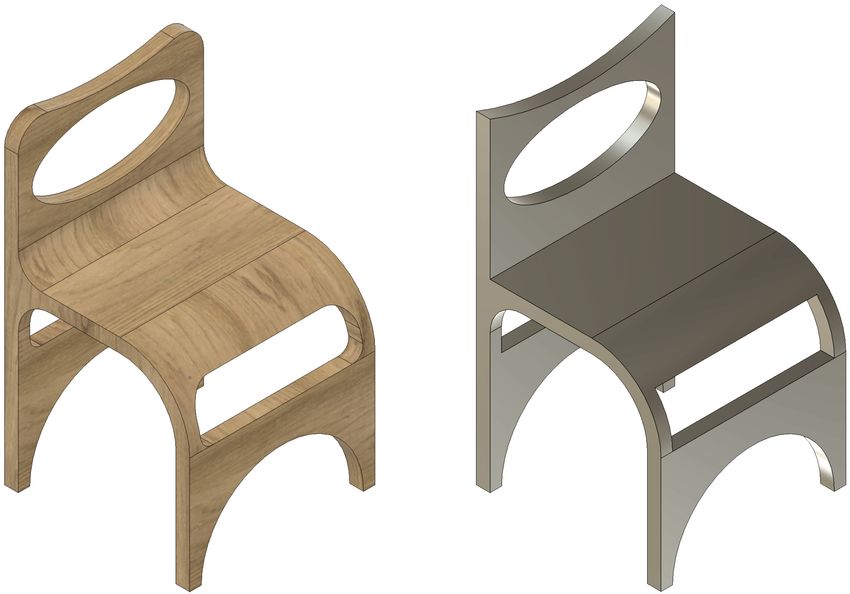
Fusion 360 Gallery: A Dataset and Environment for Programmatic CAD
Construction from Human Design Sequences
KARL D.D. WILLIS, Autodesk Research, USA
YEWEN PU, Autodesk Research, USA
JIELIANG LUO, Autodesk Research, USA
HANG CHU, Autodesk Research, Canada
TAO DU, Massachusetts Institute of Technology, USA
JOSEPH G. LAMBOURNE, Autodesk Research, United Kingdom
ARMANDO SOLAR-LEZAMA, Massachusetts Institute of Technology, USA
WOJCIECH MATUSIK, Massachusetts Institute of Technology, USA

 Sketch 1 Extrude 1 Sketch 2 Extrude 2 Extrude 9

Fig. 1. Top: A subset of designs containing ground-truth CAD programs represented as construction sequences from the Fusion 360 Gallery reconstruction
dataset. Bottom: An example construction sequence using the sketch and extrude modeling operations with built-in Boolean operations.

Parametric computer-aided design (CAD) is a standard paradigm used to language with just the sketch and extrude modeling operations, and a dataset
design manufactured objects, where a 3D shape is represented as a program of 8,625 human design sequences expressed in this language. We also present
supported by the CAD software. Despite the pervasiveness of parametric an interactive environment called the Fusion 360 Gym, which exposes the
CAD and a growing interest from the research community, currently there sequential construction of a CAD program as a Markov decision process,
does not exist a dataset of realistic CAD models in a concise programmatic making it amendable to machine learning approaches. As a use case for
form. In this paper we present the Fusion 360 Gallery, consisting of a simple our dataset and environment, we define the CAD reconstruction task of
 recovering a CAD program from a target geometry. We report results of
Authors’ addresses: Karl D.D. Willis, Autodesk Research, San Francisco, California, applying state-of-the-art methods of program synthesis with neurally guided
USA, karl.willis@autodesk.com; Yewen Pu, Autodesk Research, San Francisco, Califor-
 search on this task.
nia, USA; Jieliang Luo, Autodesk Research, San Francisco, California, USA; Hang Chu,
Autodesk Research, Toronto, Ontario, Canada; Tao Du, Massachusetts Institute of Tech-
nology, Cambridge, Massachusetts, USA; Joseph G. Lambourne, Autodesk Research, CCS Concepts: • Computing methodologies → Parametric curve and
Soho, London, United Kingdom; Armando Solar-Lezama, Massachusetts Institute of surface models.
Technology, Cambridge, Massachusetts, USA; Wojciech Matusik, Massachusetts Insti-
tute of Technology, Cambridge, Massachusetts, USA.
 Additional Key Words and Phrases: Computer aided design, CAD, dataset,
Permission to make digital or hard copies of all or part of this work for personal or construction, geometry synthesis, reconstruction
classroom use is granted without fee provided that copies are not made or distributed
for profit or commercial advantage and that copies bear this notice and the full citation
on the first page. Copyrights for components of this work owned by others than the ACM Reference Format:
author(s) must be honored. Abstracting with credit is permitted. To copy otherwise, or Karl D.D. Willis, Yewen Pu, Jieliang Luo, Hang Chu, Tao Du, Joseph G.
republish, to post on servers or to redistribute to lists, requires prior specific permission Lambourne, Armando Solar-Lezama, and Wojciech Matusik. 2021. Fusion
and/or a fee. Request permissions from permissions@acm.org.
© 2021 Copyright held by the owner/author(s). Publication rights licensed to ACM.
 360 Gallery: A Dataset and Environment for Programmatic CAD Construc-
0730-0301/2021/8-ART54 $15.00 tion from Human Design Sequences. ACM Trans. Graph. 40, 4, Article 54
https://doi.org/10.1145/3450626.3459818 (August 2021), 24 pages. https://doi.org/10.1145/3450626.3459818

 ACM Trans. Graph., Vol. 40, No. 4, Article 54. Publication date: August 2021.
54:2 • Karl D.D. Willis, Yewen Pu, Jieliang Luo, Hang Chu, Tao Du, Joseph G. Lambourne, Armando Solar-Lezama, and Wojciech Matusik

1 INTRODUCTION • We present the Fusion 360 Gallery reconstruction dataset,
The manufactured objects that surround us in everyday life are containing 8,625 human designed CAD programs, expressed
represented programmatically in computer-aided design (CAD) soft- in a simple yet expressive language of sketch and extrude.
ware as a sequence of 2D and 3D modeling operations. Parametric • We introduce an environment called the Fusion 360 Gym,
CAD files contain programmatic information that is critical for doc- capable of executing the language of sketch and extrude and
umenting design intent, maintaining editablity, and compatibility providing a geometric data structure as feedback after each
with downstream simulation and manufacturing. Embedded within operation.
these designs is the knowledge of domain experts who precisely • We standardize the task of CAD reconstruction from input
define a sequence of modeling operations to form 3D shapes. We geometry and use a learning-based approach with neurally
believe having access to a real-world collection of human design guided search to produce results on real world data for the
sequences, and the ability to execute them, is critical for future first time.
advances in CAD that leverage learning-based approaches.
 Learning-based approaches show great potential, both for solving
existing problems such as reverse engineering [Buonamici et al.
2018], and for providing entirely new kinds of functionality which
would be unimaginable using traditional techniques. Recent ad-
 2 RELATED WORK
vances in neural networks have spurred new interest in data driven
approaches to generating CAD programs, tackling both the forward CAD Datasets. Existing 3D CAD datasets have largely focused on
problem of 3D shape generation [Jones et al. 2020; Li et al. 2020b; providing mesh geometry [Chang et al. 2015; Kim et al. 2020; Mo
Mo et al. 2019a] and the inverse problem of recovering CAD pro- et al. 2019b; Wu et al. 2015; Zhou and Jacobson 2016]. However, the
grams from a target geometry [Ellis et al. 2019; Kania et al. 2020; de facto standard for parametric CAD is the boundary representa-
Sharma et al. 2017; Tian et al. 2019]. However, progress has been tion (B-Rep) format, containing valuable analytic representations
inhibited by the lack of a human designed dataset of ground-truth of surfaces and curves suitable for high level control of 3D shapes.
CAD programs, written in a simple yet expressive Domain Specific B-Reps are collections of trimmed parametric surfaces along with
Language (DSL) and an environment to execute them. topological information which describes adjacency relationships
 We take a step towards this goal by introducing the first dataset between them [Weiler 1986]. B-Rep datasets have recently been
of human designed CAD geometries, paired with their ground-truth made available with both human designed [Koch et al. 2019] and
CAD programs represented as construction sequences, along with synthetic data [Jayaraman et al. 2020; Starly 2020; Zhang et al. 2018].
a supporting execution environment to make learning-based ap- Missing from these datasets is programmatic construction sequence
proaches amendable to real CAD construction tasks. Our dataset information containing the knowledge of how each shape is defined
contains 8,625 CAD programs represented entirely in a simple lan- and created. Although the ABC dataset includes some additional
guage allowing sketches to be created and then extruded. With just construction information in a proprietary format provided by the
the sketch and extrude modeling operations, that also incorporate Onshape CAD software, missing information can only be retrieved
Boolean operations, a highly expressive range of 3D designs can be by querying the OnShape API. Combined with sparse documenta-
created (Figure 1). We provide an interactive environment called tion, this makes it difficult to interpret the construction information.
the Fusion 360 Gym, which can interpret the language of sketch and We are unaware of any method that can be used to rebuild designs
extrude, providing a geometric data structure as feedback after each in the ABC dataset from the provided construction information, a
operation, simulating the iterative construction process of a human key requirement for tasks related to CAD construction. We believe
designer. it is critical to understand not only what is designed, but how that
 As a use case for our dataset and environment, we standardize design came about.
the problem of programmatic CAD reconstruction from a target Parametric CAD programs contain valuable information on the
geometry using a learning-based approach. We provide a bench- construction history of a design. Schulz et al. [2014] provide a stan-
mark, consisting of a training set of 6,900 designs and a test set dard collection of human designs with full parametric history, albeit
of 1,725 designs, and a set of evaluation criteria. We then develop a limited set of 67 designs in a proprietary format. SketchGraphs
neurally guided search approaches for the CAD reconstruction task [Seff et al. 2020] narrows the broad area of parametric CAD by fo-
on this benchmark. Our algorithm consists of first training a policy, cusing on the underlying 2D engineering sketches, including sketch
a message passing network (MPN) with a novel encoding of state construction sequences. Freehand 2D sketch datasets also tackle
and action, using imitation learning on ground truth construction the challenge of understanding design by looking at the sequence
sequences. At inference time the algorithm employs search, leverag- of user actions [Eitz et al. 2012; Gryaditskaya et al. 2019; Sangkloy
ing the learned neural policy to repeatedly interact with the Fusion et al. 2016]. In the absence of human designed sequential 3D data,
360 Gym environment until a correct CAD program is discovered. learning-based approaches have instead leveraged synthetic CAD
This approach is able to recover a correct CAD program for 67.5% construction sequences [Ellis et al. 2019; Li et al. 2020b; Sharma et al.
of designs in the test set with a budget of 100 interactions between 2017; Tian et al. 2019]. The dataset presented in this paper is the
the agent and the Fusion 360 Gym, averaging < 20 sec solve time per first to provide human designed 3D CAD construction sequence
design. This paper makes the following contributions: information suitable for use with machine learning. Table 1 provides
 a feature comparison of related CAD datasets.

ACM Trans. Graph., Vol. 40, No. 4, Article 54. Publication date: August 2021.
Fusion 360 Gallery: A Dataset and Environment for Programmatic CAD Construction from Human Design Sequences • 54:3

 Sketch 1 Extrude 1 Extrude 2 Sketch 2 Extrude 3
 s1 = add_sketch('XZ') add_extrude( add_extrude( s2 = add_sketch('YZ') add_extrude(
 add_line(.6, .8, .6, 2.4) sketch=s1, sketch=s1, add_line(.8, 2.8, 5.8, 2.8) sketch=s2,
 add_arc(.6, 2.4, .8, 2.4, 90) profile=p1[1], profile=p1[0::2], add_line(5.8, 2.8, 5.8, -2.8) profile=p2[0],
 add_line(.8, 2.6, 1, 2.6) distance=.8, distance=5, add_line(5.8, -2.8, .8, -2.8) distance=14,
 ... operation='NewBody') operation='Join') ... operation='Cut')
 p1 = add_line(-1, 2, -1, .8) p2 = add_line(2, .2, 2.8, .2)

Fig. 2. An example design sequence from the dataset with associated CAD program. Sketch elements form profiles that are sequentially extruded to join
(Extrude 1, Extrude 2) or cut (Extrude 3) geometry using Boolean operations. The colored areas show the sketch profiles that partake in each extrusion.

Table 1. Comparison of related CAD datasets. For each dataset, we report and Fayolle and Pasko [2016]) with heuristic rules to prune the
the number of designs (#), the design representation (B-Rep, Mesh, or search space [Buchele 2000; Buchele and Crawford 2003; Buchele
Sketch), whether it includes a construction sequence capable of rebuilding
 and Roles 2001; Shapiro and Vossler 1993]. Heuristic approaches are
the final design (Seq.), and whether it contains human annotated labels for
tasks such as shape classification (Label). The F360 Gallery row indicates also available in a number of commercial software tools, often as a
our dataset. user-guided semi-automatic system [Autodesk 2012; Dassault 2019]
 to aid with file conversion between CAD systems. These traditional
 Dataset # B-Rep Mesh Sketch Seq. Label algorithms operate by removing faces from the B-rep body and reap-
 plying them as parametric modeling operations. This strategy can
 ShapeNet 3M+ ✓ ✓
 recover the later modeling operations, but fail to completely rebuild
 ABC 1M+ ✓ ✓
 Thingi10k 10,000 ✓ ✓ the construction sequence from the first step. We instead tackle the
 SketchGraphs 15M+ ✓ ✓ task of recovering the entire construction sequence from the first
 F360 Gallery 8,625 ✓ ✓ ✓ ✓ extrusion. Another approach is using program synthesis [Du et al.
 2018; Nandi et al. 2017, 2018, 2020] to infer CAD programs written
 in DSLs from given shapes. CAD reconstruction is also related to
 the inverse procedural modeling problem [Stava et al. 2014; Talton
 3D Shape Generation. The forward problem of 3D shape genera-
 et al. 2011; Vanegas et al. 2012], which attempts to reverse-engineer
tion has been explored extensively in recent years using learning-
 procedures that can faithfully match a given target.
based approaches. Neural network based generative models are
 Compared to the rule-based or grammar-based methods above,
often used to enable previously challenging functionality such as
 learning-based approaches can potentially learn the rules that are
shape interpolation and synthesis. Notable approaches to this prob-
 typically hard-coded, automate scenarios that require user-input,
lem include leveraging knowledge of object structure [Gao et al.
 and generalize when confronted with unfamiliar geometry. One
2019; Li et al. 2020a; Mo et al. 2019a; Schor et al. 2019] or learning
 early work is CSGNet [Sharma et al. 2017], which trains a neural
from a sequence of events to generate 3D shapes [Jones et al. 2020;
 network to infer the sequence of Constructive Solid Geometry (CSG)
Li et al. 2020b; Nash et al. 2020; Sung et al. 2017; Wu et al. 2020;
 operations based on visual input. More recent works along this line
Zou et al. 2017]. Unique to our work is the challenge of learning
 of research include [Chen et al. 2020; Ellis et al. 2019; Kania et al.
from real sequential human design data, requiring a state and action
 2020; Tian et al. 2019]. Typically associated with these methods are
representation suitable for the language of sketch and extrude.
 a customized DSL, such as CSG, that parameterizes the space of ge-
 CAD Reconstruction. The inverse task of CAD reconstruction in- ometry, some heuristic rules that limit the search space, and a neural
volves recovering a CAD program, represented as a sequence of network generative model. Lin et al. [2020] reconstruct input shapes
modeling operations, from input such as B-Reps, triangle meshes, or with a dual action representation that first positions cuboids and
point clouds. Despite extensive prior work [Shah et al. 2001], CAD then edits edge-loops for refinement. Although editing edge-loops
reconstruction remains a challenging problem as it requires deduc- of cuboids may be a suitable modeling operation in artistic design, it
tions on both continuous parameters (e.g., extracting the dimensions is not as expressive or precise as the sketch and extrude operations
of primitives) and discrete operations (e.g., choosing a proper op- used in real mechanical components. Additionally, Lin et al. [2020]
eration for the next step), leading to a mixed combinatorial search choose to train and evaluate their network on synthetic data due to
space. To recover the sequence of operations, traditional methods the lack of a benchmark dataset of CAD construction sequences, a
typically run global search methods (e.g., evolutionary algorithms space that our work aims to fill. Our approach is the first to apply a
as in Hamza and Saitou [2004], Weiss [2009], Friedrich et al. [2019],

 ACM Trans. Graph., Vol. 40, No. 4, Article 54. Publication date: August 2021.
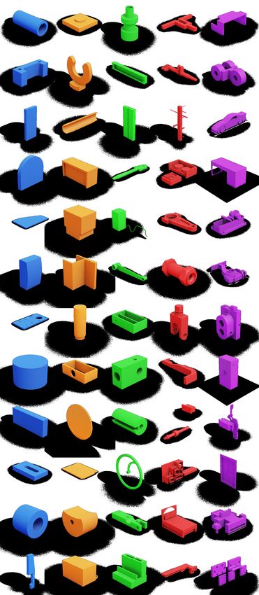
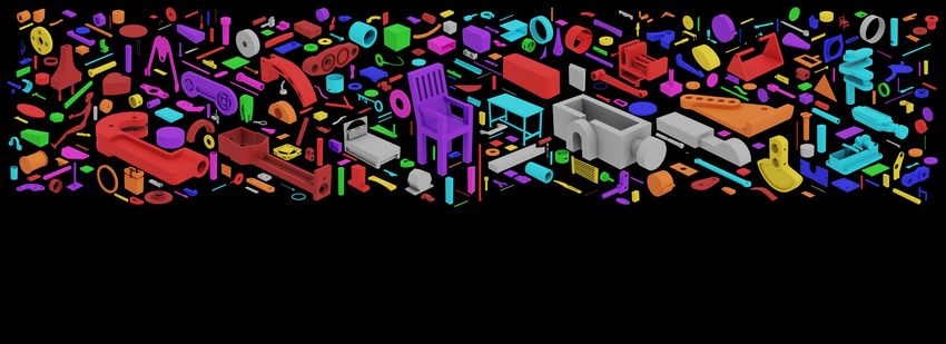
54:4 • Karl D.D. Willis, Yewen Pu, Jieliang Luo, Hang Chu, Tao Du, Joseph G. Lambourne, Armando Solar-Lezama, and Wojciech Matusik

 Number of Extrude Operations
 1 2 5 10 15+

Fig. 3. Modeling operations other than sketch and extrude are suppressed to
expand the data quantity. An example design before (left) and after (right)
the fillet modeling operation is suppressed.

learning-based method to reconstruction using common sketch and
extrude CAD modeling operations from real human designs.

3 FUSION 360 GALLERY DSL AND RECONSTRUCTION
 DATASET
The Fusion 360 Gallery reconstruction dataset consists of 8,625 de-
signs produced by users of the CAD software Autodesk Fusion 360
and submitted to the publicly available Autodesk Online Gallery [Au-
todesk 2015]. The data and supporting code is publicly available via
GitHub1 with a license allowing non-commercial research similar
to the ImageNet [Deng et al. 2009] license. We created the dataset
from approximately 20,000 designs in the native Fusion 360 CAD file
format. We focus on the sketch and extrude modeling operations for
two main reasons: 1) sketch and extrude are the two most common
CAD modeling operations used in 84% and 79% of designs in the
original dataset respectively; >3x more common than operations
such as fillet and chamfer, and 2) we seek to balance design ex-
pressivity with a tractable problem for learning-based approaches;
restricting the modeling operations to sketch and extrude greatly
simplifies the descriptive complexity compared to the full range of
CAD modeling operations. We generate the as-designed sequence
of sketch and extrude modeling operations by parsing the parametric
history of the Fusion 360 CAD files. Multi-component assemblies
are divided into separate designs representing the constituent parts,
e.g. the blade of a pocket knife. Modeling operations other than
sketch and extrude are suppressed to expand the data quantity. Fig-
ure 3 shows an example of suppressing a fillet operation, allowing
the resulting design to be included in the dataset. Figure 4 shows
a random sampling of the designs in the dataset grouped by the
number of extrude operations used.
 Each design is represented as a program expressed in a DSL,
forming a simplified wrapper around the underlying Fusion 360
Python API [Autodesk 2014]. Each design consists of a sequence Fig. 4. A random sampling of designs from the Fusion 360 Gallery recon-
 struction dataset, grouped by the number of extrude operations.
1 Dataset website: https://github.com/AutodeskAILab/Fusion360GalleryDataset

ACM Trans. Graph., Vol. 40, No. 4, Article 54. Publication date: August 2021.

Fusion 360 Gallery: A Dataset and Environment for Programmatic CAD Construction from Human Design Sequences • 54:5

Table 2. The grammar for the Fusion 360 Gallery domain-specific language. N1,2
A program consists of a sequence of sketch and extrude operations that
iteratively modify the current geometry. N1,2
 N5
 := ; [ ] N3
 := | N3,4 N3,4 N1,2
 := add_sketch( ); [ ]
 Line L Arc A Circle C
 := | |
 := add_line( , , , ) Fig. 5. Sketch commands used to create a Line , Arc , and Circle .
 := add_arc( , , , , )
 := add_circle( , , )
 := add_extrude([ ], , )
 := identifier
 := number
 := new body | join | cut | intersect

 Join Cut

of sketch and extrude operations that iteratively modifies the cur-
rent geometry (Figure 2). We specify the core language here, and
provide information on additional constructs, such as sketching of
splines and double-sided extrudes, in Section A.1 of the appendix.
The Fusion 360 Gallery DSL is a stateful language consisting of a
single global variable , representing the current geometry under
 New Body Start Body + Sketch Intersect
construction, and a sequence of commands [ ] that iteratively mod-
ifies the current geometry . Each command can be either a sketch
 or an extrude operation. A grammar describing the core DSL is Fig. 6. Extrude operations include the ability to Boolean with other geome-
shown in Table 2. try. From the start body shown in the center, a sketch is extruded to form a
 new body overlapping the start body, join with the start body, cut out of
3.1 Current Geometry the start body, or intersect with the start body.

The current geometry is the single global state that is updated with
the sequence of commands [ ]. It is a data structure representing all
geometric information that would be available to a designer in the group of triangles in the .obj file with the B-Rep face identifier as the
construction process using Fusion 360: such as inspecting different group name. This allows the triangles to be traced back to the B-Rep
aspects of the geometry, and referencing its components for further face and associated extrude operation. Any intermediate geometry
modifications. can also be exported in these file formats with the API.
 Boundary Representation. B-Rep is the primary geometry format
provided in the dataset and the native format in which designs were 3.2 Sketch
created, making it a natural representation for the current geometry. A sketch operation, , is stated by specifying the plane on which
 represents a collection of sketch or B-Rep entities, which can the sketch will be created using the add_sketch( ) command.
be referenced from the construction sequence through identifier . is a plane identifier, which allows for identification of the three
B-Rep bodies can be expressed as a face adjacency graph, as later canonical planes , , along with other planar faces present
described in Section 4.1. in the current geometry . Following the identification of a sketch
 Execution. Crucially, the current geometry is iteratively up- plane, one can add a sequence of sketch commands [ ], where each
dated through the sequence of commands [ ]. After each command command is either a line , arc , or circle (Figure 5). Line, arc, and
 , the interpreter uses the underlying Fusion 360 Python API to circle represent 95% of curves in the dataset. A line command is
generate an updated geometry. After all the commands [ ] are specified by four numbers, representing the coordinates for the start
executed, we obtain the final geometry, . and end points. A circle command is specified by three numbers,
 two representing the circle’s center and one representing its radius.
 Storage. In addition to the program , Fusion 360 Gym stores the An arc command is specified by five numbers, representing the
final geometry as a .smt file, the native B-Rep format used by start point, the arc’s center point, and the angle which the arc
Fusion 360, and neutral .step files that can be used with other CAD subtends. The coordinates for the line , arc , and circle are
systems. B-Rep entities, such as bodies and faces, can be referenced specified with respect to the coordinate system of the chosen sketch
from the construction sequence back to entities in the .smt file. A plane in . Executing a sketch command creates a list of new
mesh representation of is stored in .obj format representing a profiles in the current geometry , consisting of enclosed regions
triangulated version of the B-Rep. Each B-Rep face is labeled as a resulting from the sketch.

 ACM Trans. Graph., Vol. 40, No. 4, Article 54. Publication date: August 2021.
54:6 • Karl D.D. Willis, Yewen Pu, Jieliang Luo, Hang Chu, Tao Du, Joseph G. Lambourne, Armando Solar-Lezama, and Wojciech Matusik

 REWARD

 STATE

 ENVIRONMENT AGENT
 Fusion 360 Gym

 Current Geometry Target Geometry

 ACTION
 Modeling Operation

Fig. 7. The Fusion 360 Gym environment interacts with an agent in a se- Fig. 8. For state representation we use a face adjacency graph with B-Rep
quential decision making scenario. The state contains the current and target faces as graph vertices and B-Rep edges as graph edges.
geometries. The agent outputs an action, in the form of a modeling operation,
that advances the current geometry towards the target.
 • transition: Fusion 360 Gym implements the transition func-
 tion that applies the modeling operation to update the current
 geometry.
3.3 Extrude • reward: The user can define custom reward functions de-
An extrude operation takes a list of identifiers, [ ], referencing a pending on the task. For instance, the agent might receive a
list of profiles in the current geometry , and extrudes them from 2D reward of 1 if the current geometry exactly matches the target
into 3D. A signed distance parameter defines how far the profile geometry.
is extruded along the normal direction. The Boolean operation
specifies whether the extruded 3D volume is added to, subtracted 4.1 State Representation
from, or intersected with other 3D bodies in the design. Figure 6 In order for an agent to successfully reconstruct the target geometry,
shows a start body and sketch (center) that is extruded to form it is important that we have a suitable state representation. In the
two separate overlapping bodies, joined to form a single body, cut Fusion 360 Gym, we use a similar encoding scheme to Jayaraman
through the start body to split it in two, or intersected with the start et al. [2020] and represent the current and target geometry with a
body. Additional extrude options are available such as two-sided B-Rep face-adjacency graph [Ansaldi et al. 1985], which contains
extrude, symmetrical extrude, and tapered extrude (See Section A.1.6 additional information amenable to a learning agent not present
of the appendix). Executing an extrude operation results in an in the language of the Fusion 360 Gallery DSL (Figure 8). Crucial
updated list of bodies in the current geometry . The combination to this encoding are the geometric features of the elements, such
of expressive sketches and extrude operations with built in Boolean as point-locations, and topological features specifying how these
capability enables a wide variety of designs to be constructed from elements are connected to each other. Specifically, the vertices of the
only two modeling operations (Figure 1). face-adjacency graph represent B-Rep faces (trimmed parametric
 surfaces) in the design, with graph vertex features representing
4 FUSION 360 GYM the size, orientation, and curvature of the faces. The edges of the
 face-adjacency graph represent B-Rep edges in the design, that
Together with the dataset we provide an open source environment,
 connect the adjacent B-Rep faces to each other. Additional details
called the Fusion 360 Gym, for standardizing the CAD reconstruction
 are provided in Section A.3.2 of the appendix.
task for learning-based approaches. The Fusion 360 Gym further
simplifies the Fusion 360 Gallery DSL and serves as the environment
 4.2 Action Representation
that interacts with an intelligent agent for the task of CAD recon-
struction (Figure 7). Just as a designer can iteratively interact with a In the Fusion 360 Gym we support two action representations en-
CAD software system in a step-by-step fashion, comparing at each compassing different modeling operations: sketch extrusion and face
step the target geometry to be recovered and the current geometry extrusion.
they have created so-far, the Fusion 360 Gym provides the intelligent 4.2.1 Sketch Extrusion. Sketch extrusion mirrors the Fusion 360
agent with the same kind of interaction. Specifically, the Fusion 360 Gallery DSL closely. In this scheme, the agent must first select a
Gym formalizes the following Markov Decision Process: sketch plane, draw on this plane using a sequence of curve primi-
 tives, such as lines and arcs, to form closed loop profiles. The agent
 • state: Contains the current geometry, and optionally, the then selects a profile to extrude a given distance and direction (Fig-
 target geometry to be reconstructed. We use a B-Rep face- ure 9, top). Using this representation it is possible to construct novel
 adjacency graph as our state representation. geometries by generating the underlying sketch primitives and ex-
 • action: A modeling operation that allows the agent to modify truding them by an arbitrary amount. Although all designs in the
 the current geometry. We consider two action representations: Fusion 360 Gallery reconstruction dataset can be constructed using
 sketch extrusion and face extrusion. sketch extrusion, in practice this is challenging. Benko et al. [2002]

ACM Trans. Graph., Vol. 40, No. 4, Article 54. Publication date: August 2021.
Fusion 360 Gallery: A Dataset and Environment for Programmatic CAD Construction from Human Design Sequences • 54:7
SKETCH EXTRUSION

 Sketch 1 Sketch Extrude 1 Sketch 2 Sketch Extrude 2
FACE EXTRUSION

 Face Extrude 1 Face Extrude 2

 Fig. 9. Action representations supported by the Fusion 360 Gym include low-level sketch extrusion (top) and simplified face extrusion (bottom).

 show that to generate sketches suitable for mechanical engineering dataset. In Section 6.2 we evaluate the performance of synthetic and
 parts, the curve primitives often need to be constructed alongside semi-synthetic data for the CAD reconstruction task. We provide
 a set of constraints which enforce regularities and symmetries in examples of synthetic data in Figure 15 and commands for the Fusion
 the design. Although the construction of constraint graphs is fea- 360 Gym in Section A.2 of the appendix.
 sible using techniques like the one shown by Liao et al. [2019],
 enforcing the constraints requires a complex interaction between 5 CAD RECONSTRUCTION TASK
 the machine learning algorithm and a suitable geometric constraint
 5.1 Task Definition
 solver, greatly increasing the algorithm complexity. We alleviate this
 problem by introducing a simplified action representation, called The goal of CAD reconstruction is to recover a program, represented
 face extrusion, that is well suited to learning-based approaches. as a sequence of modeling operations used to construct a CAD model
 with only the geometry as input. This task can be specified using
 4.2.2 Face Extrusion. In face extrusion, a face from the target design different input geometry representations, including B-Rep, mesh, or
 is used as the extrusion profile rather than a sketch profile (Figure 9, point cloud, with progressively lower fidelity. Each representation
 bottom). This is possible because the target design is known in presents a realistic scenario where parametric CAD information is
 advance during reconstruction. An action in this scheme is a triple absent and needs to be recovered. Given a target geometry , we
 {face , face , op} where the start and end faces are parallel wish to find a sequence of CAD modeling operations (actions) A =
 faces referenced from the target geometry, and the operation type { 0, 1, · · · } such that, once executed in a CAD software system,
 is one of the following: new body, join, cut, intersect. The start face results in a geometry where every point in space is in its interior,
 defines the extrusion profile and the end face defines the distance if and only if, it is also in the interior of .
 to be extruded and does not need to match the shape of the start
 face. Target constrained reconstruction using face extrusion has the 5.2 Evaluation Metrics
 benefit of narrowly scoping the prediction problem with shorter We prescribe three evaluation metrics, IoU, exact reconstruction,
 action sequences and simpler actions. Conversely, not all geometries and conciseness. IoU measures the intersection over union of and
 can be reconstructed with this simplified strategy due to insufficient : iou( , ) = | ∩ |/| ∪ |. Exact reconstruction measures
 information in the target, e.g., Extrude 3 in Figure 2 cuts across the whether iou( , ) = 1. As multiple correct sequences of CAD
 entire design without leaving a start or end face. modeling operations exist, a proposed reconstruction sequence A
 need not match the ground truth sequence  provided an exact
 4.3 Synthetic Data Generation reconstruction is found. To measure the quality of exact reconstruc-
 The Fusion 360 Gym supports generation of synthetic designs for tions we consider the conciseness of the construction sequence. Let
 data augmentation. In addition to procedurally generated synthetic conciseness(A, Â ) = |A|/| Â |, where a score ≤ 1 indicates the
 data, semi-synthetic data can be generated by taking existing designs agent found an exact reconstruction with equal or fewer steps than
 and modifying or recombining them. For instance, we can randomly the ground truth, and a score > 1 indicates more inefficient exact
 perturb the sketches and the extrusion distances, and even ‘graft’ reconstructions.
 sketches from one design onto another. We also support distribution
 matching of parameters, such as the number of faces, to ensure that 5.3 Neurally Guided Search
 synthetic designs match a human designed dataset distribution. We now present a method for CAD reconstruction using neurally-
 Learning-based systems can leverage semi-synthetic data to expand guided search [Devlin et al. 2017; Ellis et al. 2019; Kalyan et al. 2018;
 the number of samples in the Fusion 360 Gallery reconstruction Tang et al. 2019] from B-Rep input using face extrusion modeling

 ACM Trans. Graph., Vol. 40, No. 4, Article 54. Publication date: August 2021.
54:8 • Karl D.D. Willis, Yewen Pu, Jieliang Luo, Hang Chu, Tao Du, Joseph G. Lambourne, Armando Solar-Lezama, and Wojciech Matusik
STATE AGENT ACTION
v 4
t
v
3
t h 0
t
new body
vt5 .
vt2 . join
.
MPN MLP cut
Gt vt0
vt1 h 5
t intersect
vc3 { facestart , faceend , op }
vc2 hc0
.
MPN . Σ hc
vc0 .
Gc v 1
c hc3
Fig. 10. Given a state comprising the target geometry and current geometry , both of which are represented as a graph, the agent uses message passing
networks (MPNs) to predict an action as a face extrusion modeling operation. The first MPN in the bottom branch produces a set of node embedding vectors
h 0 · · · h 3 , which are summed over to produce the hidden vector for the current geometry h . Another MPN in the top branch produces a set of node embedding
vectors h 0 · · · h 5 , which are concatenated with h to predict the action. We condition the end face prediction on the predicted start face. Colors in the figure
correspond to different graph nodes.
operations. The training phase consists of imitation learning, where the action using a multi-layer perceptron (MLP), with the end face
a policy is trained to imitate a known construction sequence from conditioned on the vertex embedding of the predicted start face.
a given geometry. The testing / inference phase leverages search, We denote the learned vertex embedding vectors produced by
where the search algorithm repeatedly samples the trained policy
the two MPN branches as {h } and {h } for the current output and
for actions and applies these actions in the environment to generate target graphs, respectively. We estimate the probability of the -th
a set of candidate reconstruction sequences. operation type, and the -th face being the start face or end face as:
Õ
5.3.1 Imitation Learning. To perform imitation learning, we lever-
= h , h = h (2)
age the fact that we have the ground truth sequence of modeling
operations (actions) Â = { ˆ ,0 · · · ˆ , −1 } for each design in
= softmax h , h (3)
the dataset. We feed the ground truth action sequence  into the
Fusion 360 Gym, starting from the empty geometry 0 , and out-
˜
= softmax h , h , h , . . ˜ = argmax
(4)
put a sequence of partial constructions ,1 · · · , where , =
. We then collect the supervised dataset D = {( 0, ) →
ˆ ,0, ( ,1, ) → ˆ ,1 · · · } and train a supervised agent that where , , and denote linear layers that take the con-
takes the pair of current-target constructions ( , ) to a mod- catenated vectors as input.
eling operation action , which would transform the current ge-
5.3.3 Search. Given a neural agent ( |( , )) capable of fur-
ometry closer to the target. Formally, we optimize the expected
thering a current geometry toward the target geometry, we can
log-likelihood of correct actions under the data distribution:
amplify its performance at test time using search. This allows us to
explore multiple different reconstruction sequences at once, at the
( , )∼D log ˆ | , (1) expense of extended interactions with the environment. By lever-
aging search, one gets the benefit of scaling: the larger budget we
5.3.2 Agent. The agent (Figure 10) takes a pair of geometries ( , ) have to interact with the environment, the more likely we are going
as state, and outputs the corresponding face-extrusion action = to succeed in recovering a working reconstruction sequence. The
{face , face , op}. The two geometries , are given using effectiveness of search is measured against a search budget, which in
a face-adjacency graph similar to Jayaraman et al. [2020], where our case, is the number of environment steps executed in the Fusion
the graph vertexes represent the faces of the geometry, with vertex 360 Gym. We consider the following standard search procedures
features calculated from each face: 10×10 grid of 3D points, normals, from the neurally guided search literature:
and trimming mask, in addition to the face surface type. The 3D
points are global xyz values sampled in UV parameter space of the • random rollouts: This search procedure uses the learned pol-
face. The edges define connectivity of adjacent faces. Inputs are icy to sample a sequence of steps in the environment. Every
encoded using two separate message passing networks [Gilmer et al. rollout consists of iterations; at each iteration an action is
2017; Kipf et al. 2018; Kipf and Welling 2016] aggregating messages chosen according to . This action is executed in the environ-
along the edges of the graph. The encoded vectors representing ment by taking an environment step and the updated current
the current geometry are summed together (h in Figure 10), and geometry is presented back to the policy to sample the next
concatenated with the encoded vertexes of the target geometry action. is capped to a fixed rollout length of max( 2 , 2),
(h 0 · · · h 5 in Figure 10). The concatenated vectors are used to output where is the number of planar faces in . If the agent
ACM Trans. Graph., Vol. 40, No. 4, Article 54. Publication date: August 2021.Fusion 360 Gallery: A Dataset and Environment for Programmatic CAD Construction from Human Design Sequences • 54:9 Table 3. Reconstruction results for IoU and exact reconstruction at 20 and Reconstruction IoU 100 environment steps using random rollouts with different agents trained 1.0 on human designed data. The best result in each column is shown in bold. 0.9 Lower values are better for conciseness. 0.8 Agent IoU Exact Recon. % Concise. 0.7 IoU 20 Steps 100 Steps 20 Steps 100 Steps 0.6 gat 0.8742 0.9128 0.6191 0.6742 1.0206 gcn 0.8644 0.9042 0.6232 0.6754 1.0168 0.5 gin 0.8346 0.8761 0.5901 0.6301 1.0042 mlp 0.8274 0.8596 0.5658 0.5965 0.9763 0.4 rand 0.6840 0.8386 0.4157 0.5380 1.2824 0.3 0 20 40 60 80 100 Environment Step gat gcn gin mlp rand fails to recover the target geometry in the current roll-out, we restart with a new roll-out and repeat the process. Fig. 11. Reconstruction IoU over 100 environment steps using random roll- outs with different agents trained on human designed data. • beam search: We rollout in parallel the top-k (where k is the beam width) candidate construction sequences for itera- tions. Each sequence is ranked by the generation probability under , ( 1 . . . ): Cumulative Exact Reconstructions 1.0 0.9 Ö ( 1 . . . ) = ( | , ) Exact Reconstruction % Estimated Representation Upper Limit =1... 0.8 At each iteration, we consider all possible extensions to the 0.7 top-k candidates by one action under , and re-rank the 0.6 extended candidate sequences under , keeping the top-k ex- tended candidates. Then, for each of the extended sequences, 0.5 we execute a step in the environment to obtain the updated 0.4 current geometries. Each run of the beam search results in environment steps. If the current sequences reaches the 0.3 0 20 40 60 80 100 rollout length without recovering the target geometry, the Environment Step beam search restarts with the beam width doubled, allowing Ground Truth gat gcn gin mlp rand it to search a wider range of candidates. Fig. 12. Cumulative exact reconstructions over 100 environment steps using • best first search: This search procedure explores the search random rollouts with different agents trained on human designed data. The space by maintaining a priority queue of candidate sequences, estimated upper limit of the face extrusion action representation is shown where the priority is ordered by . At each iteration, we at 0.8. dequeue the top candidate sequence and extend it by one action under , and these extended sequences are added back to the queue. An environment step is taken in a lazy fashion when the top candidate sequence is dequeued, and not when • How does training a neural policy under human designed, the extended sequences are added back to the queue. This synthetic, and augmented data affect CAD reconstruction process continues until the dequeued top candidate recovers performance? the target geometry. • How do different neurally guided search procedures from the 6 EVALUATION literature perform on the CAD reconstruction task? We proposed a general strategy consisting of neurally guided search, powered by a neural-network trained via imitation on human de- For evaluation, we track the best IoU the agent has discovered so signed, synthetic, and augmented data. To justify this strategy, we far, and whether exact reconstruction is achieved as a function of perform ablation studies, comparing our approach against a set of environment steps. We cap the total search budget to 100 steps to baselines on the Fusion 360 Gallery reconstruction dataset. We seek reflect a real world scenario. For experiments using human design to answer the following: data we train on the 59.2% of the training set that can be directly converted to a face extrusion sequence. We evaluate on the full test • How do different neural representations, when used to repre- set in all cases. We estimate that approximately 80% of designs in our sent the agent’s policy , perform on the CAD reconstruction dataset can be reconstructed by finding alternative face extrusion task? sequences and note this when reporting exact reconstruction results. ACM Trans. Graph., Vol. 40, No. 4, Article 54. Publication date: August 2021.
54:10 • Karl D.D. Willis, Yewen Pu, Jieliang Luo, Hang Chu, Tao Du, Joseph G. Lambourne, Armando Solar-Lezama, and Wojciech Matusik

6.1 Comparing Different Neural Representations Table 4. Reconstruction results for IoU and exact reconstruction at 20 and
 100 environment steps using random rollouts and gcn agents trained on hu-
We evaluate five different kinds of neural network representations man designed data (real), a mixture of human designed and semi-synthetic
for to understand how different networks perform on the CAD data (aug), semi-synthetic data (semi-syn), and synthetic data (syn). The
reconstruction task. The rand agent uniformly samples from the best result in each column is shown in bold. Lower values are better for
available actions to serve as a naive baseline without any learning. conciseness.
mlp is a simple agent using a MLP that does not take advantage
of message passing via graph topology. gcn, gin, and gat are MPN Agent IoU Exact Recon. % Concise.
agents that use a Graph Convolution Network [Kipf and Welling 20 Steps 100 Steps 20 Steps 100 Steps
2016], Graph Isomorphism Network [Xu et al. 2018], and Graph real 0.8644 0.9042 0.6232 0.6754 1.0168
Attention Network [Veličković et al. 2017] respectively. We use two aug 0.8707 0.8928 0.6452 0.6701 0.9706
MPN layers for all comparisons, with standard layer settings as semi-syn 0.8154 0.8473 0.5780 0.6104 1.0070
described in Section A.3.2 of the appendix. syn 0.6646 0.7211 0.4383 0.4835 1.0519
 We report the reconstruction IoU and exact reconstructions using
random rollout search for each agent as a function of the number
of environment steps in Figure 11 and 12 respectively. We detail the
 Reconstruction IoU
 1.0
exact results at step 20 and 100 in Table 3. Step 20 represents the
point where it is possible to perform exact reconstructions for all de- 0.9
signs in the test set. We also detail the conciseness of the recovered 0.8
sequence for exact reconstructions. We note that all neurally guided
 0.7

 IoU
agents outperform the random agent baseline. The topology infor-
mation available with a MPN is found to improve reconstruction 0.6
performance. The gat and gcn agents show the best performance 0.5
but fall well short of exact reconstruction on all designs in the test
set, demonstrating that the CAD reconstruction task is non-trivial 0.4
and an open problem for future research. 0.3
 0 20 40 60 80 100
 Environment Step
6.2 Comparing Human and Synthetic Data Performance real aug semi-syn syn
We evaluate four gcn agents trained on different data sources to
 Fig. 13. Reconstruction IoU over 100 environment steps using random roll-
understand how synthetic data performs compared to human design
 outs and gcn agents trained on human designed data (real), a mixture of
data. real is trained on the standard human design training set. syn human designed and semi-synthetic data (aug), semi-synthetic data (semi-
is trained on synthetic data from procedurally generated sketches of syn), and synthetic data (syn).
rectangles and circles extruded randomly (Figure 15, top). Leverag-
ing basic primitives is a common method to generate synthetic data
for program synthesis [Ellis et al. 2019; Li et al. 2020b; Sharma et al. Cumulative Exact Reconstructions
 1.0
2017], that typically results in less sophisticated designs compared
to human design data. semi-syn is trained on semi-synthetic de- 0.9
 Exact Reconstruction %

signs that use existing sketches in the training set with two or more Estimated Representation Upper Limit
 0.8
extrude operations to match the distribution of the number of faces
in the training set (Figure 15, bottom). This approach results in more 0.7
complex designs than the pure synthetic designs. We deliberately 0.6
use these two approaches for data generation to better compare
 0.5
human design data to synthetic data in different distributions. aug
is trained on the human design training set mixed with additional 0.4
semi-synthetic data. We hold the training data quantity constant 0.3
across agents, with the exception of the aug agent that contains a 0 20 40 60 80 100
 Environment Step
larger quantity from two sources. All agents are evaluated on the
 Ground Truth real aug semi-syn syn
standard human design test set.
 Figure 13 and 14 show that training on human design data offers
 Fig. 14. Cumulative exact reconstructions over 100 environment steps using
a significant advantage over synthetic and semi-synthetic data for random rollouts and gcn agents trained on human designed data (real), a
reconstruction IoU and exact reconstructions respectively. For the mixture of human designed and semi-synthetic data (aug), semi-synthetic
aug agent reconstruction performance is aided early on by data data (semi-syn), and synthetic data (syn). The estimated upper limit of the
augmentation. We attribute this early performance improvement face extrusion action representation is shown at 0.8.
to semi-synthetic designs with 1 or 2 extrusions appearing similar
to human designs. Conversely, we observe that semi-synthetic de-
signs with multiple randomly applied extrusions appear less and less similar to human design due to the random composition of

ACM Trans. Graph., Vol. 40, No. 4, Article 54. Publication date: August 2021.
Fusion 360 Gallery: A Dataset and Environment for Programmatic CAD Construction from Human Design Sequences • 54:11

 Reconstruction IoU
 1.0
 0.9
 0.8
 0.7

 IoU
 0.6
 0.5
 0.4
 0.3
 0 20 40 60 80 100
 Environment Step
 best rand beam

 Fig. 16. Reconstruction IoU over 100 environment steps using the gcn agent
 with best first search (best), random rollout search (rand) and beam search
 (beam).

 Cumulative Exact Reconstructions
Fig. 15. Top: example synthetic data created by extruding circles and rect- 1.0
angles. Bottom: example semi-synthetic data created by extruding human
designed sketches.
 Exact Reconstruction % 0.9
 Estimated Representation Upper Limit
 0.8
Table 5. Reconstruction results for IoU and exact reconstruction at 20 and
 0.7
100 environment steps using gcn agents with best first search (best), random
rollout search (rand) and beam search (beam). The best result in each column 0.6
is shown in bold. Lower values are better for conciseness.
 0.5
 Agent IoU Exact Recon. % Concise. 0.4
 20 Steps 100 Steps 20 Steps 100 Steps
 0.3
 0 20 40 60 80 100
 best 0.8831 0.9186 0.5971 0.6348 0.9215 Environment Step
 rand 0.8644 0.9042 0.6232 0.6754 1.0168
 Ground Truth best rand beam
 beam 0.8640 0.8982 0.5739 0.6122 0.9275
 Fig. 17. Cumulative exact reconstructions over 100 environment steps using
 the gcn agent with best first search (best), random rollout search (rand) and
extrusions. This difference in distribution between human and syn- beam search (beam). The estimated upper limit of the face extrusion action
thetic designs becomes more prevalent as search progressess. Table 4 representation is shown at 0.8.
provides exact results at environment step 20 and 100.

6.3 Qualitative Results
Figure 18 shows a visualization of ground truth construction se- The performance of rand for exact reconstruction can be explained
quences compared with the reconstruction results from other agents by the limited search budget of 100 environment steps: the rand algo-
using random search. The rollout with the highest IoU is shown with rithm is more likely to sample distinct sequences for a small number
the IoU score and total environment steps taken. Steps that don’t of samples, whereas beam will sample half its sequences identical
change the geometry or occur after the highest IoU are omitted to the previous rounds before the doubling, and best might not be
from the visualization. sampled enough to explore a sequence long enough to contain the
 correct program.
6.4 Comparing Search Procedures We expect beam and best to outperform rand as the number
We compare the effects of three different search procedures from of search budget increases, similar to Ellis et al. [2019]. However,
the neurally guided search literature. Here, rand is random rollout, the limitation of the search budget is important, as each design in
beam is beam search, and best is best-first search. For each search our test set takes between 5-35 seconds to reconstruct on average.
algorithm we use the gcn agent described in Section 6.1 trained on The majority of evaluation time is spent inside the Fusion 360 Gym
the standard human design training set. Figure 16, 17, and Table 5 executing modeling operations and graph generation, both com-
show that all three search algorithms perform similarly for recon- putationally expensive yet crucial operations that must be taken
struction IoU, while rand performs best for exact reconstruction. during reconstruction.

 ACM Trans. Graph., Vol. 40, No. 4, Article 54. Publication date: August 2021.
54:12 • Karl D.D. Willis, Yewen Pu, Jieliang Luo, Hang Chu, Tao Du, Joseph G. Lambourne, Armando Solar-Lezama, and Wojciech Matusik

 gt IoU Steps gt IoU Steps

 aug 1.00 2 aug 0.95 2

 gcn 1.00 5 gcn 0.99 8

 mlp 0.93 30 mlp 0.91 74

rand 0.61 99 rand 0.90 7

 gt IoU Steps gt IoU Steps

 aug 1.00 2 aug 0.37 3

 gcn 1.00 26 gcn 0.49 8

 mlp 0.93 1 mlp 0.31 31

rand 0.93 5 rand 0.37 38

 gt IoU Steps gt IoU Steps

 aug 0.84 3 aug 0.79 79

 gcn 0.84 90 gcn 0.71 96

 mlp 0.85 9 mlp 0.00 100

rand 0.84 53 rand 0.50 9

 Fig. 18. Qualitative construction sequence results comparing the ground truth (gt) to reconstructions using different agents with random rollout search.

6.5 Discussion Conciseness should always be considered alongside exact recon-
For practical application of CAD reconstruction it is necessary to struction performance as naive approaches that only reconstruct
have an exact reconstruction where all details of a design are recon- short sequences can achieve good conciseness scores.
structed in a concise way. It is notable that incorrect reconstructions
can score well with the IoU metric, but omit important design details.
For example, the small holes in the USB connector in Figure 18b are 7 CONCLUSION AND FUTURE DIRECTIONS
omitted from the gcn reconstruction. We suggest IoU should be a In this paper we presented the Fusion 360 Gallery reconstruction
secondary metric, with future work focusing on improving exact dataset and environment for learning CAD reconstruction from se-
reconstruction performance with concise construction sequences. quential 3D CAD data. We outlined a standard CAD reconstruction
 task, together with evaluation metrics, and presented results from a
 neurally guided search approach.

ACM Trans. Graph., Vol. 40, No. 4, Article 54. Publication date: August 2021.
Fusion 360 Gallery: A Dataset and Environment for Programmatic CAD Construction from Human Design Sequences • 54:13

7.1 Limitations Autodesk. 2015. Autodesk Online Gallery. https://gallery.autodesk.com
 Pal Benko, Geza Kos, Pál Benkő, Laszlo Andor, Géza Kós, Tamas Varady, László Andor,
Our dataset contains only designs created using sketch and extrude and Ralph Martin. 2002. Constrained Fitting in Reverse Engineering.
rather than the full array of CAD modeling operations. Short con- Suzanne Fox Buchele. 2000. Three-dimensional binary space partitioning tree and con-
 structive solid geometry tree construction from algebraic boundary representations.
struction sequences make up a sizable portion of the data: 3267/8625 (2000).
(38%) of designs have only a single extrude operation. From the Suzanne F Buchele and Richard H Crawford. 2003. Three-dimensional halfspace con-
single extrude designs, some exhibit more complexity: 347 have >1 structive solid geometry tree construction from implicit boundary representations.
 In Proceedings of the eighth ACM symposium on Solid modeling and applications.
sketch profile resulting in ≥1 bodies from a single extrude opera- 135–144.
tion, and 998 have ≥8 sketch curves. Other designs are washers, Suzanne F Buchele and Angela C Roles. 2001. Binary space partitioning tree and
pegs, and plates, common in mechanical CAD assemblies. We avoid constructive solid geometry representations for objects bounded by curved surfaces..
 In CCCG. Citeseer, 49–52.
filtering simple designs to ensure the dataset is representative of Francesco Buonamici, Monica Carfagni, Rocco Furferi, Lapo Governi, Alessandro Lapini,
user-designed CAD. Spline curves represent 4% of curves in the and Yary Volpe. 2018. Reverse engineering modeling methods and tools: a survey.
 Computer-Aided Design and Applications 15, 3 (2018), 443–464. https://doi.org/10.
dataset and are not currently supported by our high-level DSL, 1080/16864360.2017.1397894 arXiv:https://doi.org/10.1080/16864360.2017.1397894
however they can be reconstructed via the reconstruct_curve() Angel X Chang, Thomas Funkhouser, Leonidas Guibas, Pat Hanrahan, Qixing Huang,
command (Section A.2.1). Zimo Li, Silvio Savarese, Manolis Savva, Shuran Song, Hao Su, et al. 2015. Shapenet:
 An information-rich 3d model repository. arXiv preprint arXiv:1512.03012 (2015).
 The success of the rand agent demonstrates that short construc- Zhiqin Chen, Andrea Tagliasacchi, and Hao Zhang. 2020. Bsp-net: Generating compact
tion sequences can be solved by a naive approach. This is due to meshes via binary space partitioning. In Proceedings of the IEEE/CVF Conference on
several factors: 1) our action representation that uses B-Rep faces, Computer Vision and Pattern Recognition. 45–54.
 Dassault. 2019. Solidworks FeatureWorks. https://help.solidworks.com/2019/english/
2) our search procedure discarding invalid actions, and 3) designs SolidWorks/fworks/c_Overview_of_FeatureWorks.htm
in the dataset with a low number of planar faces and extrude steps. Jia Deng, Wei Dong, Richard Socher, Li-Jia Li, Kai Li, and Li Fei-Fei. 2009. Imagenet: A
 large-scale hierarchical image database. In 2009 IEEE conference on computer vision
For example, a washer has four B-Rep faces (planar-top, cylinder- and pattern recognition. Ieee, 248–255.
inside, cylinder-outside, planar-bottom), giving the random agent Jacob Devlin, Jonathan Uesato, Surya Bhupatiraju, Rishabh Singh, Abdel-rahman Mo-
a 2/2 chance of success as either planar-top → planar-bottom, or hamed, and Pushmeet Kohli. 2017. Robustfill: Neural program learning under noisy
 i/o. arXiv preprint arXiv:1703.07469 (2017).
vice versa, are considered correct and extrusions from non-planar Tao Du, Jeevana Priya Inala, Yewen Pu, Andrew Spielberg, Adriana Schulz, Daniela
faces are invalid. Although the random agent can achieve moderate Rus, Armando Solar-Lezama, and Wojciech Matusik. 2018. Inversecsg: Automatic
success with simple designs, the problem quickly becomes challeng- conversion of 3d models to csg trees. ACM Transactions on Graphics (TOG) 37, 6
 (2018), 1–16.
ing for more complex designs. All agents struggle to achieve exact Mathias Eitz, James Hays, and Marc Alexa. 2012. How do humans sketch objects? ACM
reconstructions within the search budget for construction sequence Transactions on graphics (TOG) 31, 4 (2012), 1–10.
 Kevin Ellis, Maxwell Nye, Yewen Pu, Felix Sosa, Josh Tenenbaum, and Armando Solar-
lengths ≥4. Lezama. 2019. Write, execute, assess: Program synthesis with a repl. In Advances in
 Neural Information Processing Systems. 9169–9178.
7.2 Future Work Kevin Ellis, Daniel Ritchie, Armando Solar-Lezama, and Josh Tenenbaum. 2018.
 Learning to Infer Graphics Programs from Hand-Drawn Images. In Advances
Future extensions of this work include sample efficient search strate- in Neural Information Processing Systems, S. Bengio, H. Wallach, H. Larochelle,
gies to ensure successful recovery of construction sequences with K. Grauman, N. Cesa-Bianchi, and R. Garnett (Eds.), Vol. 31. Curran As-
 sociates, Inc., 6059–6068. https://proceedings.neurips.cc/paper/2018/file/
fewer interactions with the environment and leveraging constraints 6788076842014c83cedadbe6b0ba0314-Paper.pdf
present in the dataset to guide CAD program synthesis. More broadly Pierre-Alain Fayolle and Alexander Pasko. 2016. An evolutionary approach to the
 extraction of object construction trees from 3D point clouds. Computer-Aided
we envision the dataset can aid the creation of 3D geometry using Design 74 (2016), 1–17.
the same CAD modeling operations as human designers, exploiting Markus Friedrich, Pierre-Alain Fayolle, Thomas Gabor, and Claudia Linnhoff-Popien.
the knowledge of domain experts on how shapes are defined and 2019. Optimizing evolutionary CSG tree extraction. In Proceedings of the Genetic
 and Evolutionary Computation Conference. 1183–1191.
leveraging the strengths of industrial CAD modeling software. By Lin Gao, Jie Yang, Tong Wu, Yu-Jie Yuan, Hongbo Fu, Yu-Kun Lai, and Hao Zhang.
learning to translate point cloud, image, or mesh data into a se- 2019. SDM-NET: Deep generative network for structured deformable mesh. ACM
quence of high level modeling operations [Ellis et al. 2018; Tian et al. Transactions on Graphics (TOG) 38, 6 (2019), 1–15.
 Justin Gilmer, Samuel S Schoenholz, Patrick F Riley, Oriol Vinyals, and George E Dahl.
2019], watertight CAD models may be synthesized, providing an al- 2017. Neural message passing for quantum chemistry. In International Conference
ternative approach to the reverse engineering problem [Buonamici on Machine Learning. PMLR, 1263–1272.
 Yulia Gryaditskaya, Mark Sypesteyn, Jan Willem Hoftijzer, Sylvia Pont, Fredo Durand,
et al. 2018]. A remaining challenge is to develop representations that and Adrien Bousseau. 2019. Opensketch: A richly-annotated dataset of product
can be conditioned on the design geometry and topology created so design sketches. ACM Transactions on Graphics (TOG) 38, 6 (2019), 232.
far, leveraging the sequential nature of the data for self-attention Karim Hamza and Kazuhiro Saitou. 2004. Optimization of constructive solid geometry
 via a tree-based multi-objective genetic algorithm. In Genetic and Evolutionary
[Vaswani et al. 2017]. Finally, beyond the simplified design space Computation Conference. Springer, 981–992.
of sketch and extrude lies the full breadth of rich sequential CAD Pradeep Kumar Jayaraman, Aditya Sanghi, Joseph Lambourne, Thomas Davies, Hooman
modeling operations. Shayani, and Nigel Morris. 2020. UV-Net: Learning from Curve-Networks and Solids.
 arXiv preprint arXiv:2006.10211 (2020).
 R. Kenny Jones, Theresa Barton, Xianghao Xu, Kai Wang, Ellen Jiang, Paul Guerrero,
REFERENCES Niloy Mitra, and Daniel Ritchie. 2020. ShapeAssembly: Learning to Generate Pro-
 grams for 3D Shape Structure Synthesis. ACM Transactions on Graphics (TOG),
Silvia Ansaldi, Leila De Floriani, and Bianca Falcidieno. 1985. Geometric modeling Siggraph Asia 2020 39, 6 (2020), Article 234.
 of solid objects by using a face adjacency graph representation. ACM SIGGRAPH Ashwin Kalyan, Abhishek Mohta, Oleksandr Polozov, Dhruv Batra, Prateek Jain, and
 Computer Graphics 19, 3 (1985), 131–139. Sumit Gulwani. 2018. Neural-guided deductive search for real-time program syn-
Autodesk. 2012. Inventor Feature Recognition. https://apps.autodesk.com/INVNTOR/ thesis from examples. arXiv preprint arXiv:1804.01186 (2018).
 en/Detail/Index?id=9172877436288348979 Kacper Kania, Maciej Zięba, and Tomasz Kajdanowicz. 2020. UCSG-Net–Unsupervised
Autodesk. 2014. Fusion 360 API. http://help.autodesk.com/view/fusion360/ENU/?guid= Discovering of Constructive Solid Geometry Tree. arXiv preprint arXiv:2006.09102
 GUID-7B5A90C8-E94C-48DA-B16B-430729B734DC

 ACM Trans. Graph., Vol. 40, No. 4, Article 54. Publication date: August 2021.
You can also read


