FOXTEL MANAGEMENT PTY LIMITED - BUSINESS IQ (BIQ) IPTV INTEGRATION GUIDE FBIQ-006
←
→
Page content transcription
If your browser does not render page correctly, please read the page content below

FOXTEL MANAGEMENT PTY LIMITED
Business iQ (BiQ) IPTV Integration Guide
                     FBIQ-006
         Last Updated: 7/07/2021 9:33:00 AM
                    Revision 1.3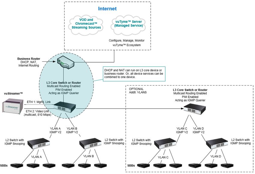
Business iQ (BiQ) IPTV Integration Guide

Document Control
© Copyright FOXTEL Management Pty Ltd. All rights reserved. This document
contains information proprietary to FOXTEL Management Pty Ltd. Except for the
purposes of evaluation, this document may not be reproduced, in whole or in part, in
any form, or distributed to any party outside of FOXTEL Management Pty Ltd, by any
means, without permission in writing, from FOXTEL Management Pty Ltd.
This document is classified to the level indicated at the top of this page. Any
classification containing the word confidence or confidential means the document is to
be placed out of sight when not in use and placed in a drawer or cupboard when the
room will be unattended. Any classification containing the word secret means the
document is always to be in someone’s hand or under secure lock when not in use.

History
  Version       Date               Author                            Description
     1.0     25/01/2021 Graham Briscoe             Initial version
     1.1     15/02/2021 Graham Briscoe             Added IGMP Querier to L2 Core Switch
                                                   requirements. Added DHCP lease duration,
                                                   Static IP address for switch, Fast-Join/Leave,
                                                   and IGMP snooping timeout to Pre-Installation
                                                   Check List
     1.2     05/07/2021 Graham Briscoe             Added Other Inhouse IP Video Content
                                                   section. Pre-install checklist revised. Added
                                                   chapter on casting. Added WiFi channels to
                                                   pre-install checklist.
     1.3     07/07/2021 Graham Briscoe             Added reference to Self Help Troubleshooting
                                                   Guide

Approval

                                                                         7th July 2021

 Graham Briscoe, Commercial Product Manager                              Date

Distribution List
 Name                              Position                                 Company
 Christopher Smith                 Commercial Product Solutions Manager     Foxtel
 Enver Vasfi                       Hardware Development Manager             Foxtel
 Steve Circosta                    Customer Technology Field Engineer       Foxtel

Printed: 7 July 2021
© FOXTEL Management Pty Ltd 2021              2
Business iQ (BiQ) IPTV Integration Guide

Disclaimer
This document is correct at time of publication. Foxtel reserves the right to modify items
within the document without prior notice to the field.

Printed: 7 July 2021
© FOXTEL Management Pty Ltd 2021           3

Business iQ (BiQ) IPTV Integration Guide

                                                 Table of Contents
Sections
       OVERVIEW ....................................................................................................................... 5
       INTEGRATION PROCESS ............................................................................................... 6
       PHYSICAL REQUIREMENTS........................................................................................... 7
       GENERAL NETWORK REQUIREMENTS ....................................................................... 7
       NETWORK REQUIREMENTS (L2 VS. L3) ...................................................................... 8
   5.1.       L2 NETWORK REQUIREMENTS ...................................................................................... 9
   5.2.       L3 NETWORK REQUIREMENTS .................................................................................... 11
       BANDWIDTH ESTIMATION ........................................................................................... 13
   6.1.       BANDWIDTH CONSUMPTION BY BIQ SERVICES ............................................................ 13
   6.2.       BIQ NETWORK BANDWIDTH PARAMETER..................................................................... 14
   6.3.       BIQ NETWORK BANDWIDTH CALCULATION .................................................................. 15
       ADDITIONAL INHOUSE IP VIDEO CONTENT .............................................................. 16
       CASTING ......................................................................................................................... 16
       SWITCH REQUIREMENTS & RECOMMENDATIONS .................................................. 17
   9.1.       L2 SWITCH REQUIREMENTS........................................................................................ 17
   9.2.       L3 CORE SWITCH REQUIREMENTS .............................................................................. 17
   9.3.       RECOMMENDED SWITCH MODELS ............................................................................... 18
          DEFINITIONS, ACRONYMS AND ABBREVIATIONS ............................................... 18
          RELATED DOCUMENT .............................................................................................. 19
          CONTACTS ................................................................................................................. 19
          PRE-INSTALLATION CHECK LIST ........................................................................... 20

Figures
Figure 1 vuStreamer™ Outlook ................................................................................................. 5
Figure 2 IP Infrastructure Overview ........................................................................................... 5
Figure 3 Integration Process ..................................................................................................... 6
Figure 4 vuStreamer Chassis Dimensions ................................................................................ 7
Figure 5 L2 Network .................................................................................................................. 9
Figure 6 L3 Network ................................................................................................................ 11

TablesTable 1 BiQ Bandwidth Consumers ............................................................................. 13
Table 2 BiQ Network Bandwidth Parameters .......................................................................... 15
Table 3 BiQ Network Bandwidth Calculation ........................................................................... 16
Table 4 Definitions, Acronyms, and Abbreviations ................................................................. 19

Printed: 7 July 2021
© FOXTEL Management Pty Ltd 2021                                   4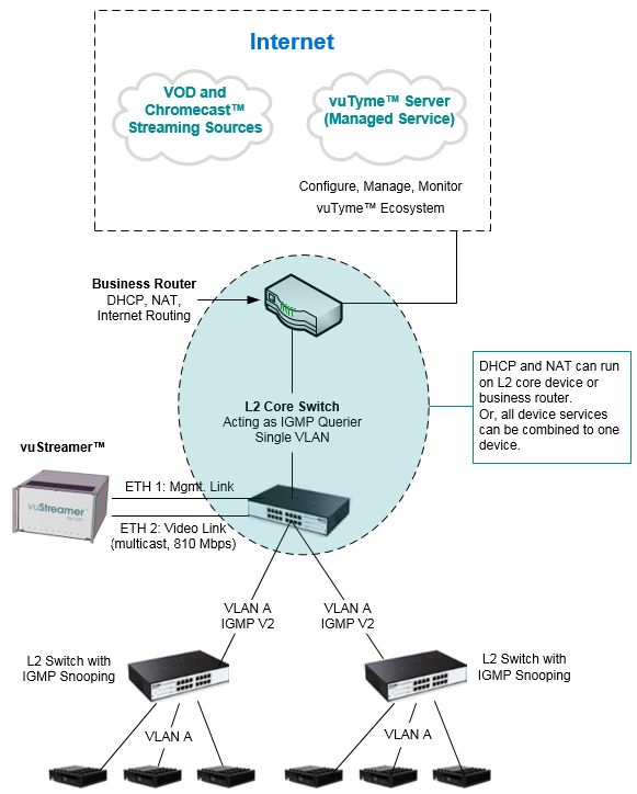
Business iQ (BiQ) IPTV Integration Guide

        Overview
This document contains the recommended IT infrastructure integration guidelines for
vuStreamer™. vuStreamer™ (see Figure 1) is a dedicated IPTV mini-headend and
part of the total Foxtel Business iQ solution.

                             Figure 1 vuStreamer™ Outlook
vuStreamer™ is designed for commercial properties wired with CAT 5e/6 and CAT 5
Ethernet. The vuStreamer™ intakes 80+ Foxtel channels plus FTA channels and
converts them to IP-based SPTS multicast streams for distribution over a property's
Ethernet network. BiQ SBBs (Set-Top-Boxes) then tune to these streams. Built on
Enterprise-grade technology, remote management & troubleshooting is inherent to the
Business iQ solution.

                           Figure 2 IP Infrastructure Overview

Printed: 7 July 2021
© FOXTEL Management Pty Ltd 2021           5
Business iQ (BiQ) IPTV Integration Guide
The diagram in Figure 2 illustrates a typical property network configured incorporating
the vuStreamer™ mini-headend, where:
• MDF – The Main Distribution Frame is typically a data center location that is the
central ingress point of all public and private lines entering a property (e.g. RF,
Telco, Broadband). From this location, these lines are connected to the internal
network which includes IDF locations.
• IDF – Intermediate Distribution Frames are typically distributed equipment/comms
rooms that intake connections from the MDF to feed network services to SBBs. In
a multi-floor property, there are often IDFs on each floor.
TV channels ingress the property via satellite and terrestrial signals. The vuStreamer™
mini-headend converts each channel into an IP multicast SPTS (Single Program
Transport Stream). These IPTV streams are injected into an Ethernet Core switch
(MDF location) and are subsequently sent to IDF switches for distribution to each
room’s set-back-box (SBB). Correct configuration of the network (via IGMP) results in
only the IP stream associated with a TV channel a SBB is tuned to being distributed to
a SBB. Guests use the SBB’s user interface to tune to a multicast channel, plus other
services such as VOD and Casting (i.e. Chromecast). VOD, Casting, and two-way
application data go through the same network path as multicast video but continue out
to the internet to obtain content.
Integration Process
PROPERTY PROPERTY FOXTEL FOXTEL
Network Deployment BiQ BiQ
Assessment Planning Installation Support
• Confirm suitability • Create network • Schedule & conduct • Monitor health of
of room for equipment list vuStreamer and BiQ service
vuStreamer • Acquire network SBB installation • Provide ongoing
installation equipment as • Confirm BiQ service remote and on-
• Confirm network needed is fully operational site technical
capacity to support • Remediate any • Confirm remote support as
Live TV, VOD, issues identified in analytics, required
Casting & BiQ App Network monitoring and
traffic Assessment troubleshooting are
• Confirm wiring from • Configure network fully operational
MDF to IDF and as per this guide.
Network
IDF toConfiguration
RG45 • Create network
Ethernet connector diagram/design
in rooms document
. • Ping test RG45 (mandatory for BiQ
Ethernet Support)
connectivity from
Switch to room
Figure 3 Integration Process
Printed: 7 July 2021
© FOXTEL Management Pty Ltd 2021 6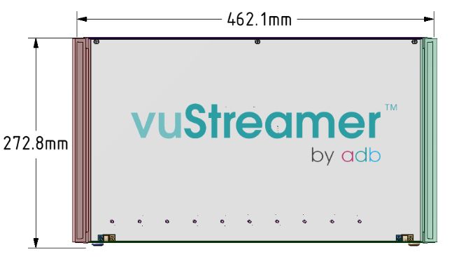
Business iQ (BiQ) IPTV Integration Guide

Figure 3 outlines the steps, responsibility and activities involved for the deployment of
the BiQ IPTV solution.

        Physical Requirements
1.    The ambient temperature of the room where vuStreamer shall be installed
      cannot exceed +5 to +40°C. Ideally vuStreamer should be installed in an
      airconditioned (temperature controlled) room.
2.    A sturdy shelf with at least 7RU (31.1cm) rack space above it is required to mount
      the vuStreamer. Note: The vuStreamer is 6RU (see Figure 4 for dimensions) but
      requires a minimum of 1RU space (4.5cm) above for heat dissipation.

                         Figure 4 vuStreamer Chassis Dimensions
3.    An AC power-point socket plus CET (Communications Earth Terminal) is
      required to be accessible from the mounting location.
4.    The vuStreamer requires connection to a satellite and/or FTA terrestrial feed.
      These feeds also need to be accessible from the mounting location.
5.    The vuStreamer requires connection to two Gigabit ports on a Core switch to
      which the vuStreamer will output video streams plus communicate with Foxtel’s
      Cloud based server across the Internet (for configuration and remote
      troubleshooting). The Core Switch needs to be accessible from vuStreamer’s
      mounting location.
6.    An RG45 Ethernet connector is required behind the TV in each room a SBB is
      to be installed.

        General Network Requirements
The following network requirements are applicable to all BiQ IPTV deployments:
1. Isolated Network – Foxtel highly recommends (but not mandatory) having an
   isolated IP network dedicated to the BiQ solution. The best way to achieve this is
   by having separate Ethernet network switches dedicated to the BiQ service and
   video delivery. All outbound traffic will join at the Internet ingress point, but this
   isolation prevents impact to the BiQ service and video delivery in the event local
   IT reconfigures parts of the network. The benefits of an isolated video network
   include:
   a. Less vulnerable to local networking changes
   b. BiQ and video traffic are not mixed with other property traffic
   c. Faster and improved support visibility and incident control

Printed: 7 July 2021
© FOXTEL Management Pty Ltd 2021           7
Business iQ (BiQ) IPTV Integration Guide
d. Allows for homogeneous network deployment (i.e. same switching network
vendors) to minimize the risk of interoperability issues.
2. VLAN / Subnet – A single VLAN should be created for the vuStreamer and the
property’s SBBs. The vuStreamer and all SBBs must be on the same subnet. If
the property desires to deploy BiQ over multiple VLANS, a L3 Core switch or
router device with PIM enabled is required (refer to section 5.2 for detail of L3
network requirements), otherwise a single VLAN may be utilised with a L2 Core
switch (refer to section 5.1 for detail of L2 network requirements).
3. Business Router and Core Switch – At the start of the network there will
typically be a business-class router that provides the following services:
a. Routing to the internet,
b. DHCP server to apportion 11x IP addresses to the vuStreamer’s internal
devices (1 switch and 10 tuner PCB cards) plus each SBB and
c. NAT
These services can alternatively be combined on a L3 Core device (switch/router)
which also provides the multicast routing of video content. If an all L2 network is
chosen, these services must run on the business-class router.
4. Static IP – Within the vuStreamer device is an Ethernet switch. This switch must
have its IP address reserved so that it does not change. The IP address should
be a local DHCP assigned IP address. The vuStreamer product labels provide
the switch MAC address to use for the IP reservation. Alternatively, the switch IP
address and all other MAC addresses of vuStreamer devices plus SBBs may be
obtained upon request from the Foxtel Commercial team.
5. GbEth Ports – The vuStreamer requires two gigabit Ethernet connections to the
Core switch which must be on the same subnet. One port is for multicast video,
the other is for device management.
6. Ports to Router / Gateway – It is important to confirm that no multicast traffic
leaks from the Core switch to which the vuStreamer connects to the upstream
router / gateway (e.g. business-class router). The switch’s uplink port to the
gateway / router should be locked down from this traffic. Most often, this is
already managed automatically.
7. Port Requirements – all communications are outgoing on port 22, 80, 123, 443,
7780, 8443 and 8453, plus 53, 67 and/or 123 if DNS, DHCP and/or NTP
respectively are managed outside of firewall. These ports shall be open to any IP
traffic from vuStreamer and SBBs.
8. Multicast Addresses –By default the IP addresses of the multicasts generated
by vuStreamer are between 239.0.0.1:10000 and 239.0.3.255:10000. The IP
address range may be changed upon request to Foxtel if there is a clash with
other multicast traffic within the same network.
Note:
• MDNS (Multicast DNS) is not required. The BiQ server informs vuStreamer what
IP address to multicast TV station on and the set-back-box know from the server
which IP address to tune to for each TV channel.
• vuStreamer audio/video multicast packets have a marking of 0x20 in case of QoS
based on DSCP.
Network Requirements (L2 vs. L3)
Refer to one of the following sections depending upon the target IT network topology
controlling vuStreamer IPTV multicast traffic; L2 multicast switching or L3 multicast
routing (via PIM).
Printed: 7 July 2021
© FOXTEL Management Pty Ltd 2021 8Business iQ (BiQ) IPTV Integration Guide
5.1. L2 Network Requirements
Follow the network recommendation described below if deploying vuStreamer to an all
Layer 2 network as illustrated in Figure 5.
Figure 5 L2 Network
1. STP (Spanning Tree Protocol) – All networks need to be configured for some
form of loop prevention even if they don't have any loops (redundant paths for
example) to start with. This setting or another like it is required to prevent network
loops but can have unintended consequences. If a network topology change
occurs, the IGMP snooping mechanism will allow a multicast flooding situation to
Printed: 7 July 2021
© FOXTEL Management Pty Ltd 2021 9Business iQ (BiQ) IPTV Integration Guide
occur to re-learn the network topology unless the no igmp snooping tcn flood
setting is made as shown below. Note: The following commands are Cisco-
specific. They may vary with other vendors.
• Set spanning-tree portfast for device ports connecting L2 switches to SBBs.
• Set spanning-tree portfast trunk on any inter-switch connected port that is
configured as a layer 2 trunk port.
• Set PVST
o spanning-tree mode pvst
• All interfaces must be set to not flood multicast upon a network topology
change. All interfaces must be set with the following “no flood” variable:
o no ip igmp snooping tcn flood
Note: If flooding were to occur resulting from a network change, the symptom would
be a momentary pixilation of the currently tuned TV station. This should be rare or
non-existent with the no igmp snooping tcn flood setting made above.
2. IGMP – IGMP is used among SBBs and switches on the LAN to track the
multicast groups, of which SBBs are members. The goal of the settings below is
to ensure that all the traffic on a given switch isn’t pushed to a single port that
feeds a SBB, thus ensuring that the only the one TV station that is being watched
goes out that port and only that port.
• All L2 switches (Core, Distribution and any Edge switches) must have IGMP
Snooping enabled so that they are able to pass the IGMP join/leave requests
to the Core switch on which an IGMP Querier is configured to properly direct
the multicast traffic. If L2 switches do not support IGMPv2, the SBBs will be
flooded with multicast traffic.
o Configure L2 multicasting (IGMP snooping) on all L2 switch interfaces. It
is also recommended that IGMP snooping be enabled on the L2 Core
switch interfaces as well.
o Configure an IGMP Querier on the L2 Core switch. The IP address
assigned to the IGMP Querier must be unique and within the same
subnet as vuStreamer and the SBBs. Note: It is highly recommended that
the IGMP Querier reside on the Core switch as it is closest to the
vuStreamer and thus the ingest point of the multicasts into the network.
• L2 IGMP snooping timeout should be at least twice the IGMP query interval.
• Fast-Join and Fast-Leave must be enabled (if not automatically done so).
3. DHCP Lease Duration – The DHCP lease duration should be extended in case
of loss of internet connectivity. The DHCP IP address lease duration should be
set to 24 hours.
4. Multicast Leakage – In a Layer 2 network, the IGMP Snooping settings, as
described above, should prevent multicast packets from ingress to the business-
class router.
Printed: 7 July 2021
© FOXTEL Management Pty Ltd 2021 10Business iQ (BiQ) IPTV Integration Guide
5.2. L3 Network Requirements
Follow the network settings described below if deploying to a Layer 3 network, which
may or may not include layer 2 Distribution (and Edge) switches as illustrated in Figure
6.
Figure 6 L3 Network
1. STP (Spanning Tree Protocol) – All networks need to be configured for some
form of loop prevention even if they don't have any loops (redundant paths for
example) to start with. This setting or another like it is required to prevent network
loops but can have unintended consequences. If a network topology change
occurs, the IGMP Snooping mechanism will allow a multicast flooding situation to
occur to re-learn the network topology unless the no igmp snooping tcn flood
setting is made as shown below. Note: The following commands are Cisco-
specific. They may vary with other vendors.
• Set spanning-tree portfast for device ports connecting L2 switches to SBBs.
• Set spanning-tree portfast trunk on any inter-switch connected port that is
configured as a layer 2 trunk port.
• Set PVST
o spanning-tree mode pvst
• All interfaces must be set to not flood multicast upon a network topology
change. All interfaces must be set with the following “no flood” variable:
o no ip igmp snooping tcn flood
Printed: 7 July 2021
© FOXTEL Management Pty Ltd 2021 11Business iQ (BiQ) IPTV Integration Guide
Note: If flooding were to occur resulting from a network change, the symptom would
be a momentary pixilation of the currently tuned TV station. This should be rare or
non-existent with the no igmp snooping tcn flood setting made above.
2. IGMP – IGMP is used among SBBs and switches on the LAN to track the
multicast groups, of which SBBs are members. Then goal of the settings below is
to ensure that all the traffic on a given switch isn’t pushed to a single port that
feeds an SBB, thus ensuring that the one TV channel that is being watched goes
out that port and only that port.
• All L2 switches (Core, Distribution and any Edge switches) must have IGMP
Snooping enabled so that they are able to pass the IGMP join/leave requests
to the Core switch to properly direct the multicast traffic. If L2 switches do not
support IGMPv2, the SBBs will be flooded with multicast traffic. Configure L2
multicasting (IGMP snooping) on all switch interfaces. It is also recommended
that IGMP snooping be enabled on the L3 core device interfaces as well.
• On L2 devices, IGMP snooping timeout should be at least twice the IGMP
query interval.
• Fast-Join and Fast-Leave must be enabled (if not automatically done so).
• If L3 switches are used, the L3 interfaces must be set as IGMP Queriers.
• The L3 device must enable the IGMPv2 protocol from the client side.
3. Enable Multicast Routing on all L3 devices expected to pass multicast traffic.
4. PIM-SSM - Protocol Independent Multicast – Source Specific Multicast allows a
SBB to receive multicast traffic directly from the source (vuStreamer). PIM-SSM
builds Shortest-Path Trees (SPTs) rooted at the source immediately (based on
join requests), as the router closest to the interested SBB is informed of the IP
address of the source for the multicast traffic. Thus, PIM-SSM bypasses the
Rendezvous Point (RP) connection stage, and through shared distribution trees,
goes directly to the source-based distribution tree.
• PIM is required where SBB are distributed over multiple VLANS (within the
same subnet) but may also be deployed in a single VLAN environment if
desired.
• L3 switches that feed L2 switches should have PIM-SSM set. Configure PIM
sparse mode on all router interfaces and issue the necessary SSM
commands, including specifying IGMPv2 on the receiver's LAN. If PIM sparse
mode is not explicitly configured on both the source and group member
interfaces, multicast packets are not forwarded.
• In SSM, an IP datagram is transmitted by a source to an SSM destination
address, and receivers can receive this datagram by subscribing to this
source and destination.
• SSM prevents traffic flooding to every router in the whole network as every
router learns the source address of the content for a multicast group. PIM
sparse mode (like any sparse mode protocol) achieves the required source
discovery functionality without flooding.
5. DHCP Lease Duration – The DHCP lease duration should be extended in case
of loss of internet connectivity. The DHCP IP address lease duration should be
set to 24 hours. Note: Double NAT-ing is not recommended (i.e. business router
and L3 switch both performing NAT).
6. Multicast Leakage – For devices connected to the L3 switch, multicast traffic
must be prevented from being forwarded to the business router/internet source.
The IGMP snooping settings as described further above should prevent multicast
packets from ingress to the business router/internet source.
Printed: 7 July 2021
© FOXTEL Management Pty Ltd 2021 12Business iQ (BiQ) IPTV Integration Guide
7. L3 Switch/Router – An optional additional L3 Core device may be connected to
the network (right side of Figure 6). In this case, L3 devices communicate
between each other using the multicast routing feature.
Important: If another L3 Core device is connected to the network, please alert
Foxtel Commercial Support in order that the Multicast Time to Live (TTL) setting
can be correctly configured for the vuStreamer device. This setting declares the
number of hops between Core devices. It is set to 1 by default. If not properly set,
multicast traffic will not be forwarded to the second Core device. This setting
would need to be changed to 2 for the network topology shown in of Figure 6.
Bandwidth Estimation
This section provides the information required to estimate the bandwidth requirements
to support the IPTV BiQ solution. The process involves:
1. Understanding the BiQ bandwidth consuming services and the average rate of
consumption per SBB.
2. Setting parameters for the specific property, the vuStreamer device, and potential
growth in bandwidth usage.
3. Using the above information to calculate:
• Floor Distribution switch bandwidth requirements
• Core switch requirements
• Internet bandwidth requirements
6.1. Bandwidth Consumption by BiQ Services
The BiQ services that consume network bandwidth can be found in Table 1.
Consumer Rate Remark
(1) 4K/UHD Live TV 30 Mbps (maximum) This represents the highest peak of bandwidth that could be
4 to 24 Mbps (typical) used by a SBB.
(2) HD Live TV 3 Mbps to 15 Mbps 720 and 1080 resolutions
(3) VOD
2.7 Mbps to 6.3 Mbps Foxtel uses MPEG-DASH adaptive bitrate streams.
(4) Casting (via
embedded Google 10 Mbps (maximum)
Chromecast) 5 Mbps (typical)
(5) BiQ Applications 256 Kbps to 512 Kbps
Table 1 BiQ Bandwidth Consumers
Except for BiQ Application traffic, all data consumers listed above are solitary, meaning
that a single SBB can only run one of the data consuming service at a time. For
instance, a SBB cannot present Casting and Live TV at the same time. The only
exception is the two-way BiQ Application traffic. BiQ Application traffic is always being
consumed by each SBB. Considering the above services, the average bandwidth
consumption per SBB is 11Mbps.
Printed: 7 July 2021
© FOXTEL Management Pty Ltd 2021 13Business iQ (BiQ) IPTV Integration Guide
6.2. BiQ Network Bandwidth Parameter
The parameter in Table 2 below must be defined, which will serve as inputs to the
BiQ network bandwidth calculation. A property of 180 rooms/SBBs is used for the
example.
Example Actual
Parameter Calculation Remark
Value Value
Property Parameters
Number of Floors 6
Over all floors, 6 in this
Total Number of SBBs 180
example.
Total Number of SBBs ¸
Average SBBs per Floor 30
Number of Floors
Full occupancy is used for
Occupancy Rate (%) 100%
example purposes.
In case future plans may
Potential SBB Expansion
0 include the addition of more
(avg. per floor)
SBBs.
Usage Parameters
For example purposes, full
(Avg. SBBs per Floor +
SBB Usage Factor per occupancy is used in this
30 Potential SBB expansion
Floor calculation and no SBB
per floor) x Occupancy rate expansion.
Growth Parameter
This factor allows room for
growth in bandwidth
consumption over time in
Growth Rate per SBB 1 Mbps
case new BiQ network
products and services are
required.
Growth Factor per Growth Rate per SBB x Example is using 30 SBBs per
30 Mbps
Floor Average SBBs per floor floor.
Printed: 7 July 2021
© FOXTEL Management Pty Ltd 2021 14Business iQ (BiQ) IPTV Integration Guide
Example Actual
Parameter Calculation Remark
Value Value
vuStreamer Parameter
810 Mbps is the vuStreamer
device outputting IPTV
streams at maximum (100%)
capacity. Current usage is in
the range of 500-600Mbps
vuStreamer Traffic 810 Mbps
(approx. 120 channels for
Movie Vault package with
availability of FTA channels
dependent on geographic
location).
Table 2 BiQ Network Bandwidth Parameters
6.3. BiQ Network Bandwidth Calculation
Bandwidth requirements shall differ dependent upon at what level of the network the
consumption takes place. As such, calculations are categorized by switch level. Most
variables in the calculations below take their values from the green parameters in the
section above.
Example Actual
Parameter Calculation Remark
Value Value
Floor Distribution Switches
If there will be significant
SBB Usage Factor per Floor differences across floors (e.g.
30 x 11
x Average Bandwidth over 5 or more SBBs), the 3
Floor Switch Input Mbps + 30
Consumption (11 Mbps) + calculations in this section of
Requirement Mbps =
Growth Factor Rate per the table should be
360 Mbps
Floor performed separately for
each floor.
30 x 11
Floor Switch Output Mbps + 30
Same equation as above
Requirement Mbps =
360 Mbps
This calculation is with respect
Floor Switch 360 Mbps
to the backplane of the
Throughput x2= Same equation as above x 2
switch, that needs to handle
Requirement 720 Mbps
both In and Out traffic.
Core Switch
810 Mbps Casting & VOD Traffic:
+ 517.5 810 Mbps is the maximum
Core Switch Input For this example, we are
(Casting rate from the vuStreamer
Requirement using 50% of SBBs
and VOD device at full capacity.
simultaneously Casting or
Traffic) + playing back VOD (180 x
Printed: 7 July 2021
© FOXTEL Management Pty Ltd 2021 15Business iQ (BiQ) IPTV Integration Guide
Example Actual
Parameter Calculation Remark
Value Value
92.16 (App 50% x 5.75 Mbps = 517.5
Traffic) = Mbps).
1419.66 Note: 5.75Mbps is the
Mbps average between a VOD
(1.420 session and a Casting
Gbps) session.
App Traffic:
For app traffic: 180 x 512
Kbps = 92.16 Mbps
Note: 512Kbps is reserved
for the app traffic.
vuStreamer Traffic +
Casting & VOD Traffic +
App Traffic
Floor Switch Input Important: If the Floor Switch
Input Requirements are
Core Switch Output
360 Mbps Requirement x Number of
performed separately by
Requirement x 6 = 2.160 Floors (or sum of each floor, add all the separate
Gbps floor’s individual switch floor requirements together
requirement) to get the total here.
1.420 Gbps Input and output added
Core Switch Input
Total Core Switch + 2.160 together to sum
Throughput Requirement + Core Switch
Gbps = requirements for switch
Output Requirement backplane.
3.580 Gbps
Table 3 BiQ Network Bandwidth Calculation
Note: The above calculations do not factor in the deployment of additional inhouse IP
video content (see chapter 7). Any such content should be added to the Core Switch
Input Requirement in addition to vuStreamer, VOD, Casting and Application traffic.
Additional Inhouse IP Video Content
A local welcome channel, promo channels and any other non-Foxtel additional content,
such as foreign language channels can be seamlessly integrated into the SBB channel
line-up. Ingestion of this inhouse IP content shall be in the form of an SPTS via Unicast
UDP (User Datagram Protocol), Multicast IGMP (Internet Group Management
Protocol) / UDP or MPEGDASH. If Multicast IGMP is used each channel shall be given
a unique multicast IP address. An address from 239.255.255.1 is recommend avoiding
the multicast traffic from vuStreamer. The inhouse multicast streams shall be ingested
into the same IPTV VLAN as the vuStreamer and it is recommended into the same
Core switch as vuStreamer.
Casting
Foxtel’s casting solution prevents a guest in one room casting to a TV in another room.
A SBB generates a WiFi AP (Access Point) when a guest selects the “Casting” option
Printed: 7 July 2021
© FOXTEL Management Pty Ltd 2021 16Business iQ (BiQ) IPTV Integration Guide
from the Foxtel main menu on the TV. Once selected a casting screen displays
instruction on how a guest connects their mobile device to the SBB unique WiFi AP.
Internet access through the WiFi AP allows a guest to control the casting session on
the integrated Chromecast (e.g. play/stop/pause streaming, change casted content or
the casting app uses), whilst still being able to receive mails and remain on social
media. The internet access is limited to 2Mbps. The bandwidth is throttled back
intentionally to force the guest to use the property’s guest WiFi network for any
significant internet usage, plus save as much of the internet bandwidth available to the
SBB as possible for the Chromecast device whilst casting.
A guest’s mobile device is disconnected from the WiFi AP one minute after casting is
exited on the TV (e.g. when the guest switches to watching live TV, plays VOD or uses
other features).
During SBB installation the channel for the Wifi AP (1 to 7 for 2.4GHz, and 36, 40 or
44 for 5GHz) shall be selected to avoid interference with neighbouring SBBs and other
Wifi APs within the property.
Switch Requirements & Recommendations
In addition to the network bandwidth requires above, switches employed in the BiQ
network have the following requirements to adequately support multicasting.
9.1. L2 Switch Requirements
1. Core Switch - Must support IGMP Querier.
2. Distribution Switch – A typical layer 2 floor switch which provides 1MbE ports
for the connection of BiQ end point SBBs and has a 1GbE uplink to the Core
switch should be sufficient for the vast majority of BiQ implementations (e.g. up
48x 100MbE ports simultaneous streaming an average of 11 Mbps per port).
3. Packets Per Second (pps)
• When used as the Core switch, the L2 switch should support 78,200 pps for
multicast throughput (using 1,358 bytes per UDP packet) for the maximum
810 Mbps total output of the vuStreamer.
• The total maximum multicast throughput of any given L2 Distribution or Edge
switch is the lesser of 78,200 pps and 2,900 pps x quantity of set-back-boxes
connected directly or indirectly to the switch.
4. IGMP Processing – It is recommended that the IGMP Snooping be implemented
on high-end switches with specialized Application-Specific Integrated Circuits
(ASICs) performing the IGMP checks in hardware. Implementing on a low-end
switch with a slow CPU may have a severe performance impact.
5. Multicast Groups - The maximum multicast groups required to be supported by
any given switch is the lesser of 200 and the quantity of set-back-boxes
connected directly or indirectly to the switch.
9.2. L3 Core Switch Requirements
The following are the requirements of a L3 Core switch:
1. Must support PIM and IGMP Querier.
2. Packets Per Second (pps) – A L3 Core switch should support 78,200 pps for
multicast throughput (using 1358 Bytes per UDP packet) for the maximum 810
Mbps total output of the vuStreamer.
Printed: 7 July 2021
© FOXTEL Management Pty Ltd 2021 17Business iQ (BiQ) IPTV Integration Guide
3. IGMP Processing – It is recommended that IGMP Snooping be implemented on
high-end switches with specialized application-specific integrated circuits (ASICs)
performing the IGMP Snooping in hardware. Implementing on a low-end switch
with a slow CPU may have a severe performance impact.
4. Multicast Groups - The maximum multicast groups required to be supported by
any given switch is the lesser of 200 and the quantity of set-back-boxes
connected directly or indirectly to the switch.
9.3. Recommended Switch Models
Core Switch - Cisco Catalyst C9200, C9300, C9500, and C3850 or equivalent
dependent on size of network.
Distribution Switch - Cisco Catalyst C9200 or equivalent.
Definitions, Acronyms and Abbreviations
Term Definition
ASIC Application Specific Integrated Circuits
BiQ Business iQ
CAT Category of Ethernet cable
CET Communications Earth Terminal
DHCP Dynamic Host Configuration Protocol
DNS Domain Name System
DSCP Differentiated Services Code Point
IDF Intermediate Distribution Frame
IGMP Internet Group Management Protocol
IP Internet Protocol
LED Light Emitting Diode
MDF Main Distribution Frame
MDNS Multicast DNS
NAT Network Address Translation
NTP Network Time Protocol
PCB Printed Circuit Board
PIM Protocol Independent Multicast
Printed: 7 July 2021
© FOXTEL Management Pty Ltd 2021 18Business iQ (BiQ) IPTV Integration Guide
QoS Quality of Service
SBB Set-Back-Box
SPTS Single Program Transport Stream
TTL Time To Live
Table 4 Definitions, Acronyms, and Abbreviations
Related Document
The documents listed below compliment this document in providing a complete
understanding of the Business iQ IPTV technology:
• FXTL-D-0298 BiQ Satellite Infrastructure Guide
• FBIQ-001 BiQ SBB Installation Guide
• FBIQ-002 BiQ vuStreamer Installation Guide
• FBIQ-005 BiQ Self Help Troubleshooting Guide
• BUS0355 BiQ Technical Overview
• CISCO 2001, IP Multicast Technology Overview, viewed 13 January
2021,
https://www.cisco.com/c/en/us/td/docs/ios/solutions_docs/ip_multicast/
White_papers/mcst_ovr.html
Contacts
Foxtel Commercial Business support:
• Phone: 1300 874 403
• Email: Business.iQ@foxtel.com.au
Printed: 7 July 2021
© FOXTEL Management Pty Ltd 2021 19Business iQ (BiQ) IPTV Integration Guide
Pre-Installation Check List
My property has a network diagram/design (e.g. As Built) document to share with
Foxtel, detailing all routers/switches/access points involved in the IPTV deployment
and identifying which switch/router the vuStreamer is to be connected to and which
switches/access points are available in each room to connect a Set-Back-Box to.
My property has a secure room in which to install the vuStreamer IPTV headend
with:
Ambient temperature +5 and +40⁰C
A sturdy shelf on which to mount the vuStreamer with at least 7RU (31.1cm)
space above
A spare AC power-point socket
A minimum of 2.5mm2 yellow green earth copper wire to ground the vuStreamer
chassis to a known electrical earth point (CET)
Two GbE ports available on the same Core switch, within the same VLAN
assigned to the Foxtel service. The port numbers are: __________________.
My property has a DHCP server to assign IP addresses to the vuStreamer (11
internal devices: 1 switch and 10 tuner PCB cards) plus each Set-Back-Box. The
IP addresses are within the same subnet (no specific range required). The IP
address range of the subnet is:________________________________________.
My property has assigned the following static DHCP IP address to the
vuStreamer’s switch:________________________.
My property’s DHCP IP address lease duration is set to ______hours.
Note: 24 hours is required for the Foxtel service,
My property’s Core, Distribution and Edge switches within the VLAN(s) assigned
to the Foxtel service support IGMPv2.
The make/model of switches are:
core:____________________________________________________________
distribution:_______________________________________________________
edge:____________________________________________________________
access point: ______________________________________________________
My property has an IGMP Querier set within the VLAN(s) allocated to the Foxtel
service. It’s unique IP address within the subnet is:________________________.
My property has IGMP Snooping enabled on all Layer 2 Distribution switches and
any Edge switches between the Core switch and the client Set-Back-Boxes.
My property has the IGMP query interval set to: ________________.
My property has the IGMP snooping timeout set to: _______________.
Note: An IGMP snooping timeout of at least twice the IGMP query interval is
required.
My property has IGMP Fast-Join and Fast-Leave enabled.
My property has a spare 100MbE capable port patched into a Layer 2 Distribution
switch (or indirectly via a Layer 2 Edge switch) behind all required TVs. This port,
to which a Set-Back-Box shall be connected, is assigned to a VLAN allocated to
the Foxtel service.
My property has the following downstream Internet bandwidth assigned to the
Foxtel service: ___________Mbps
Note: A minimum of 512Kbps downstream Internet bandwidth is required for
vuStreamer, plus for every 10 Set-Back-Boxes. Additional bandwidth is required
for VOD and/or casting depending on your requirements (see BiQ Technical
Overview for more information).
Printed: 7 July 2021
© FOXTEL Management Pty Ltd 2021 20Business iQ (BiQ) IPTV Integration Guide
My property has outgoing ports 22, 80, 123, 443, 7780, 8443 and 8453 open to the
Internet in the property’s firewall for vuStreamer and each Set-Back-Box, plus 53,
67 and/or 123 if DNS, DHCP and/or NTP respectively are managed outside of
firewall.
My property uses the following WiFi channels: ____________________________
Note: Foxtel shall configure the casting wireless access points to best avoid these
channels.
My property has a HDMI port available on all required TVs.
The contact details for onsite IT support during installation are:
name: ______________________
job title: ______________________
phone no.: ______________________
Printed: 7 July 2021
© FOXTEL Management Pty Ltd 2021 21You can also read


