Experimental Study on Crack Characteristics of Damaged Reinforced Concrete Beams strengthened with CFRP - IOPscience
←
→
Page content transcription
If your browser does not render page correctly, please read the page content below

IOP Conference Series: Earth and Environmental Science

PAPER • OPEN ACCESS

Experimental Study on Crack Characteristics of Damaged Reinforced
Concrete Beams strengthened with CFRP
To cite this article: Junhao Huang et al 2021 IOP Conf. Ser.: Earth Environ. Sci. 787 012096

View the article online for updates and enhancements.

                               This content was downloaded from IP address 46.4.80.155 on 27/07/2021 at 07:29
CEAEE 2021                                                                                                     IOP Publishing
IOP Conf. Series: Earth and Environmental Science 787 (2021) 012096                        doi:10.1088/1755-1315/787/1/012096

Experimental Study on Crack Characteristics of Damaged
Reinforced Concrete Beams strengthened with CFRP

                     HUANG Junhao1, QIAN Yongjiu1, YANG Huaping2, LI Jing3, PAN Xingwei4
                     1
                         School of Civil Engineering, Southwest Jiaotong University, Chengdu 610031, China;
                     2
                     School of Architecture and Civil Engineering, Chengdu University, Chengdu 610106,
                     China;
                     3
                         Sichuan Railway Investment Group Co. Ltd., Chengdu 610094, China;
                     4
                         China Railway Eryuan Engineering Group Co. Ltd., Chengdu 610094, China
                     corresponding author’s e-mail: hjhbridge@my.swjtu.edu.cn

                     Abstract: The bending tests of 2 control beams and 6 damaged beams strengthened with CFRP
                     (DBSC) were carried out to study the effects of adhesive layer thickness, number of CFRP layers
                     and reinforcement ratio on crack characteristics of DBSC. The test results show that the crack
                     development of the DBSC is accelerated and the crack resistance of the DBSC is reduced
                     compared with the intact beam. With the increase of the thickness of the adhesive layer, the crack
                     development of the DBSC is slowed down and the crack resistance is improved. Increasing the
                     number of CFRP layers is helpful to restrain the crack development of DBSC under high load
                     level. The increase of reinforcement ratio can significantly improve the crack resistance of
                     DBSC.

1. Introduction
Bridge is an important part of modern traffic network. A large number of existing bridges have been
working with diseases for a long time due to low engineering technical standards during construction,
inadequate management and maintenance during operation, and imminent expiry of design service life.
The hidden danger of safety cannot be ignored, and the huge economic and social costs of complete
demolition and reconstruction are unbearable. How to solve the problem to ensure the safety and
reliability of existing bridges has become a major practical demand of China and even the world[1].
    Fiber Reinforced Polymer (FRP) has been widely used in the reinforcement of existing bridges
because of its advantages such as light weight, corrosion resistance, high strength and convenient
construction. For CFRP reinforced beams, the development of cracks will not only reduce the overall
stiffness and durability of the structure, but also affect the bonding performance of CFRP-concrete
interface. Ceroni[2] found that concrete strength, reinforcement ratio and CFRP layer number would
have an impact on the bonding performance of the reinforced members by single shear test. Ueda[3]
conducted double shear test and found that with the increase of the CFRP amount, the average stress of
concrete specimens decreased, and the average and maximum spacing of cracks both decreased.
Sebastian[4] found that the peeling failure of the bond interface in the middle of the reinforced beam was
caused by the high shear stress of FRP transferred to the concrete through the bond adhesive. Smith[5]
and Lu[6] described the interface stripping failure process through the bond-slip relationship between
FRP and concrete interface. Gong[7] found that the crack load of the reinforced beam was less affected

              Content from this work may be used under the terms of the Creative Commons Attribution 3.0 licence. Any further distribution
              of this work must maintain attribution to the author(s) and the title of the work, journal citation and DOI.
Published under licence by IOP Publishing Ltd                          1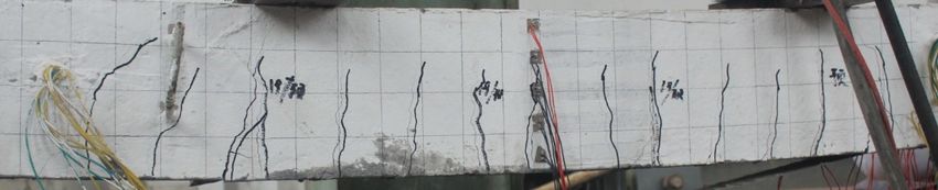
CEAEE 2021 IOP Publishing
IOP Conf. Series: Earth and Environmental Science 787 (2021) 012096 doi:10.1088/1755-1315/787/1/012096
by FRP, and FRP inhibited the crack development of the reinforced beam. The crack width and spacing
of the reinforced beam were smaller than the corresponding the unreinforced beam. Liu[8], Tan[9] and
Zhuang[10] respectively deduced the formula for calculating crack width of reinforced beams. Cao[11]
established a crack analysis model of the reinforced beam based on bond-slip theory. Lin[12] established
an analytical model to study the bond slip of CFRP-concrete interface between adjacent cracks.
These studies promote the application and development of FRP in the field of RC beam
reinforcement, but the research objects are mostly intact RC beams reinforced by FRP. In order to
accord with actual structure, this paper takes damaged beam as the object to study the influence of
adhesive layer thickness, reinforcement amount and reinforcement ratio on the crack characteristics of
damaged beams strengthened with CFRP (DBSC).
2. Experimental program
2.1. mechanical properties of materials
Standard cube specimen and standard prism were poured with the same batch of concrete poured into
the test beam, and were cured synchronously with the test beam for 28d. Based on the measured data, the
standard value of concrete’s compressive strength is 39.6MPa, the standard value of axial tensile
strength is 2.49MPa, and the elastic modulus is 2.72 104 MPa. The mechanical property parameters of
the steel bars are calculated according to Code for Design of Concrete Structures (GB 50010-2010).
Toray UT70-30 CFRP and Sikadur 330CN two-component epoxy carbon cloth impregnated adhesive
are used. The mechanical properties of the materials are shown in Table 1.
Table 1. Mechanical properties of materials
materials Mechanical properties Values
CFRP effective thickness (mm) 0.167
tensile strength (MPa) 3896
elasticity modulus (MPa) 2.39× 10⁵
ultimate tensile strain 0.0173
Adhesive tensile strength (MPa) 49.8
elasticity modulus (MPa) 2550
elongation 0.0184
flexure strength (MPa) 79.4
Tensile bond strength (MPa) 3.23
2.2. Test specimens
The specimens were simply supported beams. Each specimens was 200×120×2300mm and the
calculated span was 2100 mm. The longitudinal bars of the test beams were HRB335 steel bars (N1)
with diameters of 10 mm,12 mm,14 mm, respectively. The vertical reinforcement (N2) and stirrup (N3)
were made of HPB235 steel bars with a diameter of 6 mm. The space between stirrups in pure bending
section was 160 mm, and the space between stirrups in bending and shearing section was 100 mm. The
CFRP with the length of 1900 mm and width of 80 mm were pasted on the bottom of the specimens. The
specimens and CFRP are shown in Figure 1.
30 8×100 4×160 8×100 30
120
29
N2
200
N3
139
N1
32
100 100 1900 CFRP 100 100
80
Figure 1. Geometry and reinforcing details of test beams (unit: mm)
2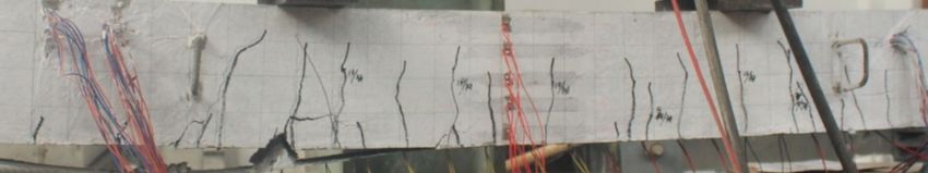
CEAEE 2021                                                                                 IOP Publishing
IOP Conf. Series: Earth and Environmental Science 787 (2021) 012096    doi:10.1088/1755-1315/787/1/012096

   A total of 8 RC beams were designed in the test. DB-1 was an unreinforced RC beam. DB-2 was a
RC beam strengthened with CFRP. JG-1 to JG-6 were damaged RC beams strengthened with CFRP
(DBSC). JG-1 to JG-3 took the thickness of the adhesive layer as the variable. JG-4 increased the
number of CFRP layers. JG-5 and JG-6 changed the reinforcement ratio of the test beam.
   The damage degree of the test beam is quantified by the damage coefficient, which is the ratio of the
pre-crack load to the ultimate load of the unreinforced reference beam (DB-1). The measured ultimate
load of DB-1 is 48.1 kN, and the damage coefficient of experimental design is 0.3, so the pre-cracking
load of JG-1 to JG-4 is 14.4 kN. Since there is no measured data of unreinforced reference beam with
corresponding reinforcement ratio, the pre-cracking loads of JG-5 and JG-6 are obtained by multiplying
the ultimate loads calculated by the finite element model and the damage coefficient 0.3, which are 11.3
kN and 18.1 kN, respectively. The design parameters of each specimen are shown in Table 2.

                           Table 2. The design parameters of each specimen
               Reinforcement          number of CFRP       adhesive layer             damage
    specimen
               ratio(%)               layers               thickness(mm)              coefficient
    DB-1       1.19                   /                    /                          /
    DB-2       1.19                   1                    0.5                        /
    JG-1       1.19                   1                    1                          0.3
    JG-2       1.19                   1                    2                          0.3
    JG-3       1.19                   1                    3                          0.3
    JG-4       1.19                   2                    1                          0.3
    JG-5       1.63                   1                    1                          0.3
    JG-6       0.82                   1                    1                          0.3

2.3. Test procedures
During the test, the hydraulic jack with the maximum lifting mass of 20 t was used to apply the load. The
jack was arranged in the position of the middle line of the distribution beam, and the distance between
the two fulcrums of the distribution beam was 700 mm. The load of the test beam was controlled before
the yield of the longitudinal bars, and the load of each stage was 2 kN. The mid-span displacement of the
test beam was used to control the loading after the yield of the longitudinal bars, and the displacement of
each stage was 1 mm. After the completion of loading at each stage, the load was held for 2 min, and the
test data were collected after the load and deformation were stabilized. The test loading device is shown
in Figure 2.

                          Figure 2. Schematic representation of the test system

3. General behavior and mode of failure
When the load reached 9.7 kN, the bottom of DB-1 beam cracked, and three initial cracks appeared near
the loading point and mid-span section. With the increase of load, several main cracks appeared
successively among the initial cracks. The width and length of each crack developed with the increase of

                                                     3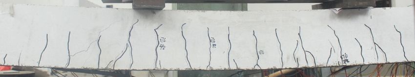
CEAEE 2021                                                                                IOP Publishing
IOP Conf. Series: Earth and Environmental Science 787 (2021) 012096   doi:10.1088/1755-1315/787/1/012096

load, and the growth of the crack near the loading point and mid-span section developed the fastest.
There were few new cracks in this stage and the crack spacing was large. After the longitudinal bars
yielded, the new cracks no longer appeared, and the developing speed of the main crack was accelerated.
Finally, the crushing of the concrete compression zone marked the end of loading. At this time, the main
crack developed to 4/5 of beam height, and there were several penetrating cracks at the bottom of the
beam, as shown in Figure 3.

                                  Figure 3. Crack distribution of DB-1

    When the loading value researched 10.8 kN, the bottom of DB-2 beam cracked, and initial cracks
appeared near the loading point and mid-span section. With the increase of load, several main cracks
appeared between the initial cracks. The width and length of each crack developed with the increase of
the load. In this stage, more new cracks appeared, and the average width and spacing of cracks were
significantly reduced compared with DB-1. There were still small oblique cracks near the main crack
after yielding of the longitudinal bars, and the development speed of the main crack was accelerated.
Finally, the loading ended with the peeling of CFRP, as shown in Figure 4.

                                  Figure 4. Crack distribution of DB-2

    JG-1 to JG-6 were damaged reinforced beams. Before formal loading, pre-cracking load with a
damage coefficient of 0.3 was applied to each specimen. The crack development process of JG-1 to
JG-6 were generally similar, and the difference was mainly reflected in the crack development rate and
final distribution pattern.
    In the process of pre-cracking loading, the initial cracks also appeared near the loading point and
mid-span section, and then a small number of secondary cracks appeared between the initial cracks. In
this stage, the crack spacing was large and the width is small. After the pre-cracking loading was
completed, the test beams were unloaded and reinforced. At the initial stage of formal loading, the width
and length of the old cracks generated by several pre-cracking loading developed with the increase of
load, while the crack spacing decreased with the emergence of new cracks, and the development of
cracks was similar to that of DB-2. With the yield of the longitudinal bars, the oblique crack appeared
near the section of the loading point. Finally, the loading ended with the peeling of CFRP cloth, as
shown in Figure 5.

                                                (a)JG-1

                                                     4
CEAEE 2021 IOP Publishing
IOP Conf. Series: Earth and Environmental Science 787 (2021) 012096 doi:10.1088/1755-1315/787/1/012096
(b)JG-2
(c)JG-3
(d)JG-4
(e)JG-5
(f)JG-6
Figure 5. Crack distribution of damaged reinforced beams
4. Test results and discussion
The crack morphology of each specimen from the beginning of loading to the yield stage of longitudinal
bars is taken as the research object.
4.1. Crack width
The average widths of the main crack in the area near the loading point section of each test beam are
taken to draw the load-crack width curve, as shown in Figure 6.
5CEAEE 2021 IOP Publishing
IOP Conf. Series: Earth and Environmental Science 787 (2021) 012096 doi:10.1088/1755-1315/787/1/012096
Figure 6. Load-crack width curve
The average crack width of DB-2 is significantly smaller than that of DB-1, indicating that CFRP
cloth has an inhibitory effect on the crack development of the reinforced beam. The average crack width
of DB-2 is less than that of JG-1, indicating that the speed of crack development of the damaged
reinforced beam is faster than that of the intact reinforced beam. Compared with JG-1, JG-2 and JG-3, it
can be seen that the three curves are very similar before the load reaches 25 kN. Before the yield of
longitudinal bars, the larger the thickness of the adhesive layer is, the smaller the average width of
cracks will be, indicating that the increase of the thickness of the adhesive layer can slow down the crack
development of the reinforced beam. Compared with JG-1 and JG-4, it can be seen that the average
crack width of the two curves is close before the load reaches 30 kN. As the load continues to increase,
the average crack width of JG-4 is less than that of JG-1, indicating that the growth of thickness of CFRP
layers can inhibit the crack development of the reinforced beam under high load level. Compared with
JG-1, JG-5 and JG-6, it can be seen that the developments of the three curves are significantly different.
The order of the average crack width from large to small is JG-6, JG-1 and JG-5, indicating that the
increase of reinforcement ratio has a significant inhibitory effect on the crack development of the
reinforced beam.
4.2. Crack characteristic
The crack characteristic of each test beam under typical load are shown in Table 3.
Table 3. Crack characteristic
Specimen Load (kN) Average spacing (mm) Average width (mm) Maximum width (mm)
DB-1 36.3 95.2 0.22 0.32
DB-2 41.8 77.3 0.15 0.25
JG-1 41.8 84.7 0.19 0.29
JG-2 42.6 82.4 0.17 0.27
JG-3 43.5 81.2 0.16 0.28
JG-4 45.3 78.6 0.17 0.25
JG-5 48.0 82.1 0.16 0.26
JG-6 36.5 85.4 0.22 0.34
6CEAEE 2021 IOP Publishing
IOP Conf. Series: Earth and Environmental Science 787 (2021) 012096 doi:10.1088/1755-1315/787/1/012096
Compared with DB-1, the average crack spacing, average crack width and maximum crack width of
DB-2 are significantly reduced, indicating that the crack resistance of the reinforced beam is improved.
The average crack spacing, average crack width and maximum crack width of DB-2 are all smaller than
that of JG-1, indicating that the crack resistance of the DBSC decreases compared with that of the intact
strengthened beam. Compared with JG-1, JG-2 and JG-3, it can be seen that the average crack spacing
and average crack width of the reinforced beam decrease with the increase of the thickness of the
adhesive layer, indicating that the increase of the thickness of the adhesive layer can enhance the crack
resistance of the reinforced beam. The yield load of JG-4 is larger than that of JG-1, and the average
crack spacing and average crack width are smaller, indicating that the increase of the number of CFRP
layers can improve the crack resistance of the strengthened beam. Compared with JG-1, JG-5 and JG-6,
it can be seen that the average spacing, average width and maximum width of cracks of the strengthened
beams decrease with the increase of reinforcement ratio, indicating that the increase of reinforcement
ratio can significantly improve the crack resistance of the strengthened beams.
5. Conclusion
The bending tests of 2 control beams and 6 DBSC were carried out to study the effects of adhesive layer
thickness, number of CFRP layers and reinforcement ratio on crack characteristics of DBSC. The
following conclusion can be drawn.
[1] Compared with the intact beams, the growth speed of cracks of DBSC is accelerated and the crack
resistance of the damaged beams is reduced.
[2] With the increase of the thickness of the adhesive layer, the crack development of the DBSC
slows down, and the average spacing and width of the crack decrease.
[3] Increasing the number of CFRP layers has little effect on the crack resistance of the beams under
low load, but it is helpful to restrain the crack development of the beams under high load.
[4] The increase of reinforcement ratio can obviously delay the crack development and enhance the
crack resistance of the reinforced beam.
References
[1] Qian Yong-jiu, Du Yan-liang. Analysis on Ways of Guaranteeing the Safety of Civil Structures in
Traffic Systems during Long Service Lives[J]. Engineering Science, 2017, 19(6): 6-11.
[2] Ceroni F, Pecce M, Matthys S. Tension Stiffening of Reinforced Concrete Ties Strengthened with
Externally Bonded Fiber-Reinforced Polymer Sheets[J]. Journal of Composites for
Construction, 2004, 8(1): 22-32.
[3] Ueda T, Yamaguchi R, Shoji K, et al. Study on Behavior in Tension of Reinforced Concrete
Members Strengthened by Carbon Fiber Sheet[J]. Journal of Composites for Construction,
2002, 6(3): 168-174.
[4] Sebastian W M. Significance of Midspan Debonding Failure in FRP-Plated Concrete Beams[J].
Journal of Structural Engineering, 2001, 127(7): 792-798.
[5] Smith S T, Gravina R J. Modeling Debonding Failure in FRP Flexurally Strengthened RC
Members Using a Local Deformation Model[J]. Journal of Composites for Construction, 2007,
11(2): 184-191.
[6] Lu X Z, Teng J G, Ye L P, et al. Intermediate Crack Debonding in FRP-strengthened RC Beams:
FE Analysis and Strength Model[J]. Journal of Composites for Construction, 2007, 11(2):
161-174.
[7] Gong Chang. Mechanical Behavior of FRP Reinforced Concrete Structure[D]. Changsha: School
of Civil Engineering Hunan University, 2011.
[8] Liu Ji-wei, Hua Ming, Zhai Rui-xing, et al. Crack Widths of Rectanglar Reinforced Concrete
Beams Strengthened with Externally Bonded CFRP Sheets[J]. Journal of Highway and
Transportation Research and Development, 2007, 24(12): 79-84.
[9] Tan Jun, Zheng Wen-zhong, Wang Ying. Calculation Method of Creak Width of Concrete Beams
Strengthened with CFRP Sheet[J]. Journal of Harbin Institute of Technology, 2010, 42(2):
7CEAEE 2021 IOP Publishing
IOP Conf. Series: Earth and Environmental Science 787 (2021) 012096 doi:10.1088/1755-1315/787/1/012096
180-185.
[10] Zhuang Jiang-bo, Ye Lie-ping, Bao Yi-zhou, et al. Crack Width of Reinforced Concrete Beams
Strengthened with CFRP Sheets[J]. Journal of Southeast University (Natural Science Edition),
2006, 36(1): 86-91.
[11] Cao Shuang-yin, Lin Xin-yan, Jing Deng-hu, et al. A Study on Cracking Behaviors of RC Beams
Strengthened with External CFRP Sheets[J]. Journal of Building Structures, 2010, 31(1):
33-40.
[12] Lin Xin-yan, Cao Shuang-yin. Study on Bond Behavior of Inter-Crack CFRP and Concrete in
Beams Strengthened with Fibers[J]. Engineering Mechanics, 2008, 25(11): 149-155.
8You can also read


