DESIGN GUIDELINES FOR ACCESSIBLE AUTOMATED VEHICLES: MOBILITY FOCUS - KATHLEEN D. KLINICH, NICHOLE R. ORTON, MIRIAM A. MANARY
←
→
Page content transcription
If your browser does not render page correctly, please read the page content below

UMTRI-2022-8                         JULY 2022

     DESIGN GUIDELINES FOR ACCESSIBLE
   AUTOMATED VEHICLES: MOBILITY FOCUS

        KATHLEEN D. KLINICH, NICHOLE R. ORTON,
                  MIRIAM A. MANARY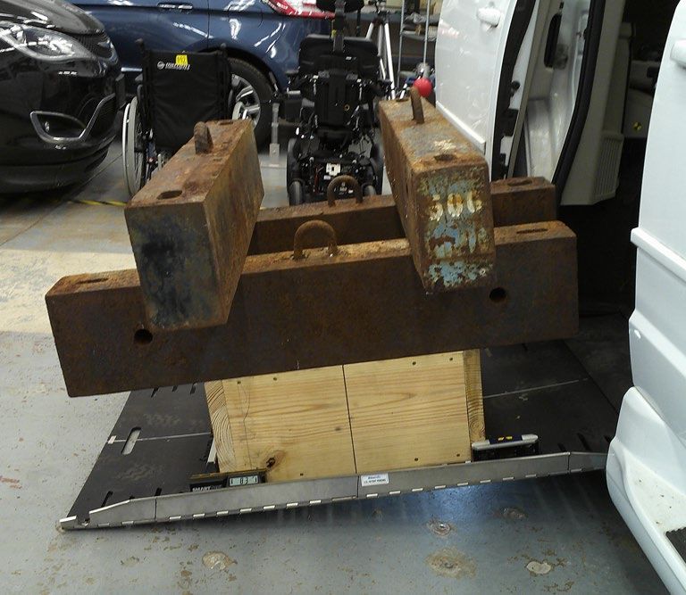
Technical Report Documentation Page
 1. Report No.                                 2. Government Accession No.                3. Recipient’s Catalog No.
 UMTRI-2022-8
 4. Title and Subtitle                                                                    5. Report Date
 Design Guidelines for Accessible Automated Vehicles: Mobility Focus                      July 2022
                                                                                          6. Performing Organization Code

 7. Author(s)                                                                             8. Performing Organization Report No.
 Kathleen D. Klinich, Nichole R. Orton, Miriam A. Manary                                  UMTRI-2022-8
 9. Performing Organization Name and Address                                              10. Work Unit No. (TRAIS)
 University of Michigan Transportation Research Institute
 2901 Baxter Rd. Ann Arbor, MI 48109                                                      11. Contract or Grant No.

 12. Sponsoring Agency Name and Address                                                   13. Type of Report and Period Covered
 Mcity                                                                                    Final July 2022
 2905 Baxter Rd. Ann Arbor, MI 48109                                                      14. Sponsoring Agency Code

 15. Supplementary Notes
 Thanks to Jennifer Bishop, Brian Eby, Joshua Fischer, Jessica Huang, Kayla Rowell, and Rishik Tatavarthi for their
 assistance in creating fixtures, drawings and analyzing data.
 16. Abstract
 Transportation for people with mobility impairments who use wheelchairs depends on
 vehicle environments that accommodate their needs for safe and easy-to-use vehicle spaces.
 This report provides design guidelines on how to make passenger vehicles, and particularly
 autonomous vehicles, accessible for people in wheelchairs. The vehicle aspects addressed
 include doorways, ramps, lifts, handholds, interior access routes, wheelchair spaces,
 wheelchair securement, occupant protection for people in wheelchairs, floor surfaces, and
 operable parts. The recommendations were derived from the literature and precedents set
 by the Americans with Disabilities Act (ADA), where applicable. In the areas of ramp strength
 and wheelchair positioning, where no clear precedents exist, the project team developed
 relevant procedures that are documented in the Appendices. This document can be used to
 evaluate vehicle accessibility using the “good/better/best” categories established for each
 topic. These guidelines promote vehicle designs that can allow more people in wheelchairs to
 travel more independently, more safely, and more easily.

 17. Key Words                                                                            18. Distribution Statement
 Accessiblity, autonomous vehicles, wheelchairs, safety, ADA
 19 Security Classif. (of this report)           20. Security Classif. (of this page)           21 No. of Pages        22. Price
 Unclassified                                    Unclassified                                   54
Form DOT F 1700.7 (8-72)                                                                Reproduction of completed page authorized

                                                                    i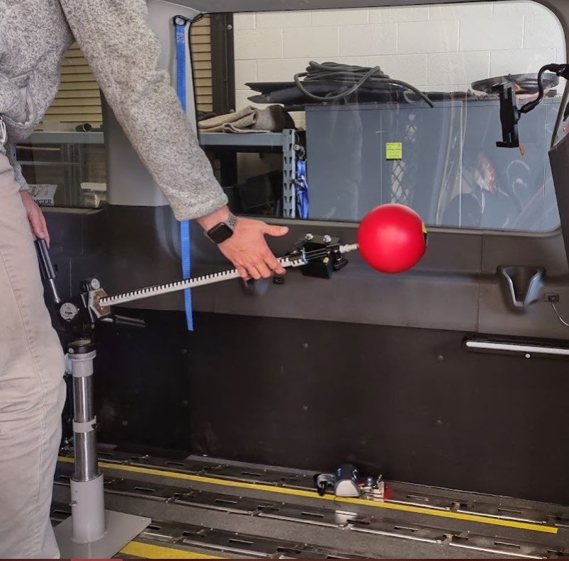
Contents
List of Figures ________________________________________________________________ iv
List of Tables _________________________________________________________________ iv
Introduction _________________________________________________________________ 1
 Overview __________________________________________________________________ 1
 Assumptions and Exclusions __________________________________________________ 1
 Definitions _________________________________________________________________ 2
Ingress/Egress _______________________________________________________________ 4
 Doorways _________________________________________________________________ 4
 Ramps ____________________________________________________________________ 6
 Lifts ______________________________________________________________________ 9
Handrails, Stanchions, and Handholds (HSH) ______________________________________ 10
Passenger Access Routes ______________________________________________________ 12
Wheelchair spaces ___________________________________________________________ 15
 Procedures _______________________________________________________________ 15
 Placement ________________________________________________________________ 15
 Dimensions _______________________________________________________________ 17
 Securement: Large Vehicles __________________________________________________ 19
 Securement: Small Vehicles __________________________________________________ 21
 Occupant restraint systems __________________________________________________ 24
 Locating Seatbelt Anchorages Relative to Wheelchair Stations ______________________ 27
Surfaces____________________________________________________________________ 31
Operable parts ______________________________________________________________ 32
References _________________________________________________________________ 33
 ADA/ADAAG ______________________________________________________________ 33
 ANSI-RESNA Procedures _____________________________________________________ 33
 FMVSS Procedures _________________________________________________________ 33
 ISO Procedures ____________________________________________________________ 34
 SAE Procedures ____________________________________________________________ 34

                                          ii
Literature ________________________________________________________________ 34
Appendix A: Relevant Federal Procedures ________________________________________ 35
  Lift Requirements __________________________________________________________ 35
  Head Impact Protection _____________________________________________________ 36
  Wheelchair Securement Anchorages and Devices ________________________________ 36
  Seatbelt Assemblies ________________________________________________________ 36
Appendix B: Relevant Procedures from SAE, RESNA, ISO _____________________________ 37
  Interior Dimensions ________________________________________________________ 37
  Surface friction ____________________________________________________________ 37
  Wheelchair Displacement ___________________________________________________ 38
Appendix C: Ramp Strength ____________________________________________________ 40
Appendix D: Wheelchair Positioning Procedure ____________________________________ 42
Appendix E: Checking Zone for Potential Head Contact ______________________________ 46
Appendix F: Checklist for vehicles
List of Figures
Figure 1. Illustration of good, better, best recommendations for door dimensions. .................... 5
Figure 2. Illustration of ramp lengths needed to meet good, better, best recommendations for
ramp angles (for a 150 mm/ in sill height), plus good, better, and best ramp widths. . 8
Figure 3. Example of wheelchair station template (left), closeup of markings (center), and back
view of Velcro placement (right).................................................................................. 12
Figure 4. Example of passenger access template. ........................................................................ 13
Figure 5. Illustration of placing different sizes of wheelchair templates relative to the better and
best circle recommendations for clear space relative to the wheelchair station. ...... 14
Figure 6. Illustration of good, better, and best recommendations for wheelchair station
dimensions. .................................................................................................................. 18
Figure 7. Illustration of ideal sideview tiedown angle between 30-45 degrees and lateral
positions of tiedowns. .................................................................................................. 22
Figure 8. Combined rear tiedown loads measured in ~1500 tests run using WC19 protocols. ... 23
Figure 9. Example of a manual wheelchair with low seatback. .................................................... 26
Figure 10. Estimated range of H-points for occupants seated in wheelchairs relative to rear
boundary of wheelchair station. .................................................................................. 28
Figure 11. Optimal D-ring location measured from pretest photos of 342 wheelchair sled tests,
with origin located at rear tiedown floor anchorage................................................... 29
Figure 12. Illustration of recommended belt geometry from NHTSA AWTORS study. ................ 30
Figure 13. Controller with flush buttons modified with soft raised extensions. .......................... 32
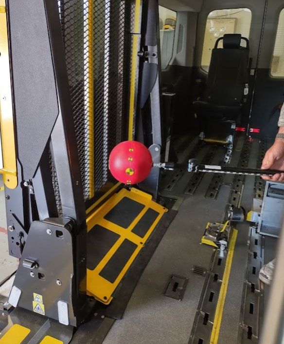
Figure 14. Demonstration photos of forward push test (left) and lateral pull test (right)........... 39
Figure 15. Placement of loading crate along ramp centerlines. ................................................... 40
Figure 16. Demonstration of static ramp strength test procedure: applying static load through
loading crate, and slope measurement before and after loading. .............................. 41
Figure 17. Illustration of ideal sideview tiedown angle between 30-45 degrees and lateral
positions of tiedowns. .................................................................................................. 43
Figure 18. Illustration of recommended belt fit. .......................................................................... 44
Figure 19. Diagram of head contact tool from 1989 FMVSS 201 procedure. .............................. 46
Figure 20. Photos demonstrating use of adapted tool, set to the forward-high location of the
wheelchair station (left). When the upper component is adjusted to the longest
setting, it would not contact the forward panel behind the driver (center) or the
stowed wheelchair lift (right). ...................................................................................... 47
Figure 21. Estimated range of H-points for occupants seated in wheelchairs relative to rear
boundary of wheelchair station. .................................................................................. 48
List of Tables
Table 1. Nominal ramp lengths needed to achieve good, better, best recommendations for
different vehicle sill heights. .......................................................................................... 7
Table 2. Test force and direction of application for measuring wheelchair displacement .......... 38
iv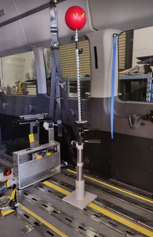
Introduction
Overview
The purpose of this document is to provide guidance on the design of automated vehicles to
improve accessibility and accommodation for people with mobility disabilities, including people
who use wheelchairs as vehicle seating. However, the recommendations are also relevant for
personal and paratransit vehicles used by passengers seated in wheelchairs. The guidelines
focus on design of the interior and ingress/egress features of the vehicle. The vehicle features
addressed include doorways, ramps, lifts, handholds, interior access routes, wheelchair spaces,
wheelchair securement, occupant protection for people in wheelchairs, floor surfaces, and
operable parts. As much as possible, we have identified three levels to consider for each
feature being evaluated: good, better, and best.
The majority of the good requirements are excerpted/adapted from the 2016 version of the
Americans with Disabilities Act Accessibility Guidelines for Transportation Vehicles (ADAAG),
and reflect minimum targeted legal requirements to be compliant with the ADA in 2022. While
the ADAAG was originally developed for public transportation (such as large buses), AVs
providing shared services will likely need to comply as well.
The ADAAG requirements were originally intended for large buses and other LATVs, where
likelihood of high severity crashes is low because of the vehicle’s high mass and travel
characteristics. While we include the ADAAG specifications for reference, we expect that the
majority of automated vehicles used by people with mobility disabilities will be of smaller size
and mass and should thus be designed for a high-g crash environment and aim for meeting
applicable federal regulations for occupant protection in private vehicles. While technologies
that allow deployment of AVs should reduce crash involvement and severity, it will be some
time before technologies are widespread enough to prevent other vehicles from crashing into
an AV, even in a geofenced area with low speed limits. For this reason, we include guidelines
for occupant protection considerations as well as accessibility.
For each topic, the specific reference providing the rationale for the guideline is included as a
footnote with a link to the source. As much as possible, we have identified current procedures
to assess requirements. Appendices include procedures (including new ones developed for
these guidelines), recommended readings, highlights from relevant literature, and links to
additional resources.

Assumptions and Exclusions
This document does not address the following topics that are included in the ADAAG:

       •   Seats
       •   Steps
       •   Communication systems
       •   Illumination

                                                1
•   Fare Boxes
       •   Level Boarding (related to infrastructure rather than vehicle)
Selected operational issues are addressed in the appendix of highlights from literature.
A vehicle would be considered large if it is longer than 25 feet (7.6 m) (ADAAG) or if it has
GVWR greater than 4,536 kg (10,000 lb.) (NHTSA). Otherwise, it should meet requirements for
small vehicles.

Definitions
From ADAAG
Boarding platform. A platform in a level boarding bus system raised above standard curb height
that aligns with the transit vehicle floor height level boarding and alighting.
Fixed route service (or fixed route). Transportation service provided by a non-rail vehicle along a
fixed schedule prescribed route.
Large transit entity. A public transportation provider that operates 100 or more buses in a fixed
route service annually.
Large non-rail vehicle. Non-rail vehicles longer than 25 feet (7.6 m).
Level boarding bus system. A bus system where at least some stops have boarding platforms
compatible with the vehicle floor height so the transition is close to level.
Non-rail vehicle. A self-propelled, rubber-tired vehicle used to provide transportation services
and intended for use on city streets, highways, or busways that constitutes either a bus, over-
the-road bus, or van.
Operable part. A component of a device or system used to insert or withdraw objects, or to
activate, deactivate, adjust, or connect to the device or system. Operable parts include, but are
not limited to, buttons, levers, knobs, smart card targets, coin and card slots, pull-cords, jacks,
data ports, electrical outlets, and touchscreens.
Small non-rail vehicle. Non-rail vehicles 25 feet (7.6 m) or less in length.
Surface discontinuities. Differences in level between two adjacent surfaces.
From NHTSA
Large vehicle: buses, school buses, and MPVs (motorized personal vehicles) other than motor
homes with a GVWR greater than 4,536 kg (10,000 lb.) per FMVSS 403.
Bridging devices: means that portion of a platform lift that provides a transitional surface
between the platform surface and the surface of the vehicle floor within the platform threshold
area.

                                                  2
From Dictionary
Handrail: a rail fixed to posts or a wall for people to hold on to for support.
Stanchion: an upright bar, post, or frame forming a support or barrier.
Handhold: something for a hand to grip on.
Bridgeplate: a mechanical, movable form of wheelchair ramp that is used on some low-floor
light rail vehicles (LRVs) to provide for wheelchair access.
Guidelines Color Scheme
Throughout this document, drawings and graphs use the following color scheme of red for
Good, yellow for Better, and blue for Best.

                                                  3
Ingress/Egress
At least one accessible way of boarding and alighting the vehicle is required, through lifts,
ramps/bridgeplates, or lowering/kneeling the vehicle to meet the roadway surface.

Doorways
Test Procedures
SAE J1100 200911 Motor Vehicle Dimensions (or the latest version available) should be used to
measure door width and height.
Good 1
Doorway thresholds should be marked with a strip that is at least 1 in (25 mm wide) and
contrasts with the surface.
Minimum vertical doorway clearance is:

    •    65 in (1650 mm) for over-the-road buses
    •    56 in (1420 mm) in small vehicles
    •    68 in (1725 mm) in large vehicles
Minimum horizontal doorway width should be 32 in (810 mm).
Better
Minimum vertical doorway clearance should be 60 in (1513 mm) 2.
Door width should be 34 in (838 mm) or more 3, measured at two locations: one 1.5 in (38 mm)
above the floor and a second at 28 in (713 mm) 4.

1 Architectural and Transportation Barriers Compliance Board, Dec. 14, 2016, Americans with
Disabilities Act (ADA) Accessibility Guidelines for Transportation Vehicles, 36 CFR Part 1192
[Docket No. ATBCB 2010–0004] RIN 3014–AA38. T602.4, p. 90627, to meet minimum standards
in 2022.
2 Steinfeld E, Paquet V, D’Souza CD, Joseph C, and Maisel J. 2010. Anthropometry of Wheeled

Mobility Project. Buffalo, NY, p. 133, based on maximum seated height measured in study.
3 Steinfeld E, Paquet V, D’Souza CD, Joseph C, and Maisel J. 2010. Anthropometry of Wheeled

Mobility Project. Buffalo, NY, p. 134, based on maximum device width measured in study.
4 Steinfeld E, Paquet V, D’Souza CD, Joseph C, and Maisel J. 2010. Anthropometry of Wheeled

Mobility Project. Buffalo, NY, p. 133, based on mean armrest height measured in study.
                                                 4
Best
Minimum vertical doorway clearance should be 65 in (1650 mm) 5.
Door width should be 36 in (864 mm) or more 6.

        Figure 1. Illustration of good, better, best recommendations for door dimensions.

5 Architectural and Transportation Barriers Compliance Board, Dec. 14, 2016, Americans with
Disabilities Act (ADA) Accessibility Guidelines for Transportation Vehicles, 36 CFR Part 1192
[Docket No. ATBCB 2010–0004] RIN 3014–AA38. T602.4, p. 90627, based on recommendations
for over-the-road buses.
6 Department of Justice. 2010. 2010 ADA Standards for Accessible Design, based on minimum

hallway width in buildings.

                                              5
Ramps
Test Procedures
Appendix C Ramp Strength
Appendix E Checking Zone for Potential Head Contact; adapted from FMVSS 201 test procedure.
Laboratory Test Procedure for FMVSS 201U: Occupant Protection in Interior Impact, Upper
Interior Head Impact Protection
Good 7
● Minimum ramp width is 30 in (760 mm).
● Ramp slope to road needs to be 9.5 degrees or less (1:6). Ramp slope to boarding
platform needs to be 7.1 degrees or less (1:8).
● Ramps need to have edge guards on each side that are at least 2 in (51 mm) tall. They
need to run from the vehicle to within 3 in (75 mm) of the end.
● Ramps 30 in (760 mm) or longer should be designed to support a 600 lb (273 kg) load,
shorter ones designed to support 300 lb load (136 kg). Factor of safety of 3 or more.
● Ramp surface perimeter needs to be marked with a stripe at least 1 in (25 mm) wide
that contrasts with main surface.
● When deployed, the gap between vehicle and ramp needs to be 5/8 in (16 mm) or less.
● When used, ramps need to be attached to the vehicle and need to be permanently
installed and power operated on large vehicles. They need to have a way to operate
manually in case of power failure.
● Ramp surfaces need to meet specifications in Surfaces section.
● Need to stow ramp when not in use.
Better
• Minimum ramp width is 34 in (838 mm) or more 8.
• Ramp slope to road is 6 degrees or less (1:10) 9.
• Taller edge guards are probably better; no data available to support a particular
recommendation.
7 Architectural and Transportation Barriers Compliance Board, Dec. 14, 2016, Americans with
Disabilities Act (ADA) Accessibility Guidelines for Transportation Vehicles, 36 CFR Part 1192
[Docket No. ATBCB 2010–0004] RIN 3014–AA38. T602.4, p. 90627, to meet minimum standards
in 2022.
8 Steinfeld E, Paquet V, D’Souza CD, Joseph C, and Maisel J. 2010. Anthropometry of Wheeled
Mobility Project. Buffalo, NY, p. 134, based on maximum device width measured in study.
9 Department of Justice. 2010. 2010 ADA Standards for Accessible Design, based on allowable
slope for buildings based on recommendations for ramp angles permitted on running slopes
with limited space.
6• Ramps are designed to support a 1000 lb (454 kg) load 10. Factor of safety of 3 or more.
• When ramp is stowed, no contactable sharp edges (Figure 2. Illustration of ramp lengths needed to meet good, better, best recommendations
for ramp angles (for a 150 mm/ in sill height), plus good, better, and best ramp widths.
8Lifts Test Procedures NHTSA provides a detailed illustrated test procedure for FMVSS 403/404 describing lift requirements. Laboratory Test Procedure for FMVSS 403 Platform Lift Systems for Vehicles Laboratory Test Procedure for FMVSS 404 Platform Lift Systems in Motor Vehicles Appendix A contains a summary of the lift requirements and procedures. Appendix E Checking Zone for Potential Head Contact; adapted from FMVSS 201U test procedure. Laboratory Test Procedure for FMVSS 201U Occupant Protection in Interior Impact, Upper Interior Head Impact Protection Good Lifts must meet the requirements of FMVSS 403. They should allow the wheelchair passenger to board the vehicle facing either toward or away from the vehicle. Better • When stowed, the lift should have no contactable sharp edges (
Handrails, Stanchions, and Handholds (HSH)
Test Procedures
ANSI-RESNA WC4, Section 10: Wheelchair containment and occupant retention systems for use
in large accessible transit vehicles: systems for rearward-facing passengers contains
dimensional specifications for locating HSH in rear-facing wheelchair stations that may be
useful when placing HSH near forward-facing wheelchair stations.
Appendix E Checking Zone for Potential Head Contact; adapted from FMVSS 201 test procedure.
Good 14
     •   Need to have handrails or stanchions at passenger doorways that allow grasping and
         use from outside the vehicle and throughout the boarding and alighting process.
     •   Small vehicles need to have HSH to assist with onboard circulation and assistance with
         seating and standing. Large vehicles need to have them on all seatbacks located
         adjacent to the aisle (except for vehicles with high-back seats, where overhead handrails
         can be used).
     •   HSH need to have rounded or eased edges.
     •   Cross section requirements:
             o Outside diameter of seatback handholds need to range from 0.875 in to 2 in (22-
                50 mm).
             o Outside diameter of round handrails and stanchions need to range from 1.25 in
                to 2 in (32 mm to 50 mm).
             o Non-circular versions need to have a perimeter between 4 in and 6.25 in (100-
                160 mm), and a cross section less than 2.25 in (57 mm).
             o Clearance between HSH and adjacent surfaces should be 1.5 in (38 mm) or more.
Better
     •   HSH should have no contactable sharp edges (
o Non-circular versions need to have a maximum section between 1.25 in to 1.4 in
(32 mm to 35 mm) and a minimum section not less than 20 mm (0.79 in).
Best
All HSH within the Zone for Potential Head Contact meet FMVSS 201U requirements.
11Passenger Access Routes
Test Procedures
During the vehicle layout/design phase, computer aided design tools can be used to evaluate
clearance circles and associated wheelchair station locations.
For in-vehicle evaluation, we recommend constructing templates out of sturdy woven fabric
(such as denim) because it can be manipulated more easily around obstacles without damage
compared to paper, cardboard, or plastic templates. Fabric should be washed before cutting.
Wheelchair template (Figure 3) should be sized to 34 x 60 in (864 x 1524 mm), with additional
stitching lines in contrasting color placed at widths of 30 and 32 in (762 and 813 mm) and
lengths of 48 and 54 in (1219 and 1372 mm). Additional stitching lines can be added to indicate
the longitudinal centerlines for each width of station, as well the estimated range of fore-aft H-
point positions located between 22 and 49 cm from the back of the template.
Access template (Figure 4) should be a circle of 60 in (1524 mm) diameter, with center point
marked, and additional stitching lines in contrasting color at 48 and 54 in (1219 and 1372 mm).
Additional stitching lines marking perpendicular centerlines are also helpful when aligning the
station template.
Figure 3. Example of wheelchair station template (left), closeup of markings (center), and
back view of Velcro placement (right).
12Figure 4. Example of passenger access template.
Good 16
Passengers in wheelchairs need to have sufficient room to move between each accessible
entrance and each wheelchair station, as well as to enter and exit wheelchair spaces.
Better 17
Aisles should be at least 34 in (864 mm) wide. The wheelchair station should fit within a 54 in
(1372 mm) diameter circle of clear space to allow room to maneuver.
16
Architectural and Transportation Barriers Compliance Board, Dec. 14, 2016, Americans with
Disabilities Act (ADA) Accessibility Guidelines for Transportation Vehicles, 36 CFR Part 1192
[Docket No. ATBCB 2010–0004] RIN 3014–AA38. T602.4, p. 90625, to meet minimum standards
in 2022.
17 Architectural and Transportation Barriers Compliance Board, Dec. 14, 2016, Americans with
Disabilities Act (ADA) Accessibility Guidelines for Transportation Vehicles, 36 CFR Part 1192
[Docket No. ATBCB 2010–0004] RIN 3014–AA38. T602.4, p. 90602, proposed in NPRM but not
adopted.
13Best
Aisles should be at least 36 in (914 mm) wide.18 The wheelchair station should fit within a 60 in
(1524) diameter circle of clear space to allow room to maneuver.19
Figure 5. Illustration of placing different sizes of wheelchair templates relative to the better
and best circle recommendations for clear space relative to the wheelchair station.
18 Department of Justice. 2010. 2010 ADA Standards for Accessible Design, based on minimum
hallway width in buildings.
19 Recommendation from BraunAbility.
14Wheelchair spaces
Procedures
Appendix E Checking Zone for Potential Head Contact; adapted from FMVSS 201U test
procedure.
Laboratory Test Procedure for FMVSS 201U Occupant Protection in Interior Impact, Upper
Interior Head Impact Protection
Placement
Good 20
• One wheelchair station is required for vehicles with length < 25 feet, two are required
for vehicles with length of > 25 feet.
• Wheelchair stations should be placed as close as possible to accessible entrance, with
one side located adjacent to passageway.
• Flip down seats over the wheelchair space are allowed when space not in use.
• Wheelchair stations should position the occupant facing the front of the vehicle. On
LATVs where passengers are allowed to stand during travel, a rear-facing station is
allowed, as long as there is at least one other station that is forward facing.
Better
Wheelchair stations are immediately adjacent to accessible entrances.
Wheelchair stations should be located to minimize chance of occupant head contact with
interior structures. Any structures should have no contactable sharp edges (Wheelchair stations should be located to minimize chance of occupant head contact with
interior structures. This means leaving a clear space 500 mm rearward of wheelchair seatback,
and 950 mm forward of occupant head 22, unless structures have been designed to meet
requirements specified by FMVSS 201U or provide occupant protection. Any structures near the
wheelchair passenger space or vehicle seating position, as determined by procedure for
Checking Zone for Potential Head Contact, should be designed to meet the requirements
specified by FMVSS 201U.
22RESNA. Wheelchair used as Seats in Motor Vehicles; ANSI/RESNA WC-4:2017 Section 19;
2017; p 19-40.
16Dimensions
Good 23
Wheelchair spaces should be at least 30 in (760 mm) wide and 48 in (1220 mm) long. It is
acceptable to locate wheelchair footrests under another seat if the space is at least 30 in (760
mm) wide, 9 in (230 mm) high, and 6 in (150 mm) deep.
Better
• Wheelchair spaces should be at least 32 in (813 mm) wide and 54 in (1372 mm) long 24.
• Tiedown hardware should be located outside the wheelchair station space to maximize
clear maneuvering space.
• Minimum vehicle ceiling height should be 60 in (1513 mm) 25.
Best
• Wheelchair spaces should be at least 34 in wide (864 mm) 26 and 60 in long (1524 mm) 27.
• Minimum vehicle ceiling height should be 65 in (1650 mm) 28.
• Tiedown hardware should be stowable to allow for easier wheelchair maneuvering.
23 Architectural and Transportation Barriers Compliance Board, Dec. 14, 2016, Americans with
Disabilities Act (ADA) Accessibility Guidelines for Transportation Vehicles, 36 CFR Part 1192
[Docket No. ATBCB 2010–0004] RIN 3014–AA38. T602.4, p. 90628, to meet minimum standards
in 2022.
24 Steinfeld, Edward, Victor Paquet, Clive D. D’Souza, Caroline Joseph, and Jordana Maisel.
2010. Anthropometry of Wheeled Mobility Project. Buffalo, NY. p. 88, to accommodate 90% of
2010 wheelchairs.
25 Steinfeld E, Paquet V, D’Souza CD, Joseph C, and Maisel J. 2010. Anthropometry of Wheeled
Mobility Project. Buffalo, NY, p. 133, based on maximum seated height measured in study.
26 Steinfeld, Edward, Victor Paquet, Clive D. D’Souza, Caroline Joseph, and Jordana Maisel.
2010. Anthropometry of Wheeled Mobility Project. Buffalo, NY. p. 88, to accommodate 95% of
2010 wheelchair widths.
27 Department of Justice. 2010. 2010 ADA Standards for Accessible Design. p. 109, to harmonize
with side entry alcove sizes in buildings.
28 Architectural and Transportation Barriers Compliance Board, Dec. 14, 2016, Americans with
Disabilities Act (ADA) Accessibility Guidelines for Transportation Vehicles, 36 CFR Part 1192
[Docket No. ATBCB 2010–0004] RIN 3014–AA38. T602.4, p. 90627, based on recommendations
for over-the-road buses.
17Figure 6. Illustration of good, better, and best recommendations for wheelchair station
dimensions.
18Securement: Large Vehicles
Procedures
ISO 10865-1:2012(E), Wheelchair containment and occupant retention systems for accessible
transport vehicles designed for use by both sitting and standing passengers — Part 1: Systems
for rearward facing wheelchair-seated passengers, First Edition, June 5, 2012
ANSI-RESNA WC4, Section 10: Wheelchair containment and occupant retention systems for use
in large accessible transit vehicles: systems for rearward-facing passengers, Annex B: Test for
Wheelchair Containment
ANSI-RESNA WC4, Section 18: Wheelchair tiedown and occupant restraint systems for use in
motor vehicles
Laboratory Test Procedure for FMVSS 222 School Bus Passenger Seating and Crash Protection,
Appendix C for checking floor/anchor strength.
Good 29
• For vehicles with a GVWR > 30,000 lb (13,08 kg), the securement should be designed for
a minimum forward longitudinal securement load is 2000 lbf (8,800 N).
• For vehicles with a GVWR < 30,000 lb (13,608 kg), the securement should be designed
for a minimum forward longitudinal securement load is 5000 lbf (22,000 N).
• When wheelchairs are secured following manufacturers’ directions, the occupied
wheelchair should move < 2 in (51 mm) under normal operating conditions.
Better
Rear-facing wheelchair stations need to have forward excursion barriers and padded head
restraints that meet requirements of ISO 10865-1:2012(E).
Best
Rear-facing wheelchair stations need to have forward excursion barriers and padded head
restraints that meet requirements of ANSI-RESNA WC4, Section 10.
Vehicle anchor points for forward-facing securement should be designed for securement loads
generated in the frontal impact test of ANSI-RESNA WC4, Section 18.
Annex F of WC19 contains specifications for a Universal Docking Interface Geometry (UDIG)
that has been proposed to allow development of docking systems that can be independently
29
Architectural and Transportation Barriers Compliance Board, Dec. 14, 2016, Americans with
Disabilities Act (ADA) Accessibility Guidelines for Transportation Vehicles, 36 CFR Part 1192
[Docket No. ATBCB 2010–0004] RIN 3014–AA38. T602.4, p. 90628, to meet minimum standards
in 2022.
19operated by the wheelchair user. Any wheelchair with UDIG-compatible attachments could be
docked with any vehicle equipped with UDIG-compatible anchors. However, until UDIG
attachments become more available, anchors should also be provided to allow use of 4-point
strap tiedowns.
Vehicle floor strength can be evaluated using procedures in Appendix C of the Laboratory Test
Procedure for School Bus Passenger Seating and Crash Protection.
20Securement: Small Vehicles
Procedures
ANSI-RESNA WC4, Section 18: Wheelchair tiedown and occupant restraint systems for use in
motor vehicles
Laboratory Test Procedure for FMVSS 222 School Bus Passenger Seating and Crash Protection,
Appendix C, for checking floor/anchor strength.
Good:
Because the crash environment of a small vehicle differs from an LATV, the static loading and
movement requirements described in ADAAG are not sufficient to provide adequate crash
protection for a person seated in a wheelchair in a small vehicle. Current designs of rear-facing
wheelchair seating stations are also not sufficient to provide adequate occupant protection in
small vehicles. Although not legally required, vehicle hardware for forward-facing securement
of wheelchairs in small vehicles should meet requirements of ANSI-RESNA WC4, Section 18.
Better 30
Vehicle anchors for forward-facing securement should meet requirements of ANSI-RESNA WC4,
Section 18.
Hardware for anchoring 4-point strap tiedown systems should be located between 48 to 51 in
(1219 and 1295 mm) apart longitudinally. Laterally, hardware should allow securement at a
range between 12 to 30 in (300 and 760 mm). As shown in Figure 7, the ideal angle for
attaching the rear 4-point strap tiedowns is 30 to 45 degrees relative to the floor. From the top
view, rear anchors should be located straight back from the wheelchair attachment points,
while the front anchors should be located in front of and outboard relative to the wheelchair
attachment points.
30RESNA. Wheelchair Tiedown and Occupant Restraint Systems for Use in Motor Vehicles;
ANSI/RESNA WC-4:2017 Section 18; 2017; pp. 1–93.
21Figure 7. Illustration of ideal sideview tiedown angle between 30-45 degrees and lateral
positions of tiedowns.
Best
FMVSS 222 procedures for evaluating the strength of wheelchair securement points on school
buses can be used to evaluate floor strength needed to secure wheelchairs. The FMVSS 222
procedure applies a load of 13344 N (3000 lbf) to each anchor. The procedure can be adapted
to apply higher loads.
Figure 8 shows the rear tiedown peak securement loads from ~1500 tests run using WC19
protocols, where the commercial wheelchair is secured to a rigid floor; these loads were
measured with a steel floor and deformation of a typical vehicle floor would mitigate loads. X-
axis values correspond to the sum of the peak left and right tiedown loads. These data can be
used to calculate a load based on the combined mass of wheelchair and occupant with or
without a wheelchair-anchored lap belt. For example, to design a floor to secure a combined
occupant weight of 500 lb using vehicle-mounted belts, the regression equation calculates the
target applied load for each anchor location to be (20.302 * 500/2)=5088 lbf using the FMVSS
222 test procedure.
2225000
Sum of peak left and right tiedown loads (lb)
20000
y = 29.738x + 20.353
R² = 0.7933
15000
10000
y = 20.302x
R² = 0.8993
5000
0
0 100 200 300 400 500 600 700
Combined WC & ATD Weight (lb)
Independent restraint Integrated restraint
Linear (Independent restraint) Linear (Integrated restraint)
Figure 8. Combined rear tiedown loads measured in ~1500 tests run using WC19 protocols.
Annex F of WC19 contains specifications for a Universal Docking Interface Geometry (UDIG)
that has been proposed to allow development of docking systems that can be independently
operated by the wheelchair user. Any wheelchair with UDIG-compatible attachments could be
docked with any vehicle equipped with UDIG-compatible anchors. However, until UDIG
attachments become more available, anchors should also be provided to allow use of 4-point
strap tiedowns.
23Occupant restraint systems
Procedures
ANSI-RESNA WC4, Section 18: Wheelchair tiedown and occupant restraint systems for use in
motor vehicles
ISO 7176-19 (2022), Wheelchairs for Use as Seats in Motor Vehicles, Annex G
Laboratory Test Procedure for FMVSS 209 Seat Belt Assemblies
Laboratory Test Procedure for FMVSS 201U Occupant Protection in Interior Impact, Upper
Interior Head Impact Protection
Laboratory Test Procedure for FMVSS 210 Seat Belt Assembly Anchorages
Good 31
Seatbelt systems for wheelchair seating stations must meet the requirements of FMVSS No.
209, and must not be used as a substitute for wheelchair securement systems.
Better 32
Seatbelt systems should comply with the requirements of WC18. Seatbelt anchorage systems
should meet requirements of FMVSS 210.
Best
The goal of occupant protection for people in wheelchairs is that they should have a level of
occupant protection that is comparable to other occupants in the vehicle. Findings from
research studies to examine occupant protection systems designed for wheelchair stations are
summarized below.
For frontal impacts, providing a lap-and-shoulder belt system with good anchorage geometry is
the first step in protecting an occupant in a wheelchair. Specific recommendations developed
through computational modeling and volunteer testing are included in the next section of this
document (Klinich et al. 2021). Simulations showed that with good belt geometry, and the
minimum wheelchair space fore/aft length of 48 in (1219 mm), likelihood was low for head
contact with a forward component during a 30 mph/20 g severity frontal crash of a midsized
male seated in a wheelchair. If optimal belt geometry is not feasible, use of a SCARAB airbag
mounted to a forward structure (back of driver’s seat) provided improved protection. A factor
31
Architectural and Transportation Barriers Compliance Board, Dec. 14, 2016, Americans with
Disabilities Act (ADA) Accessibility Guidelines for Transportation Vehicles, 36 CFR Part 1192
[Docket No. ATBCB 2010–0004] RIN 3014–AA38. T602.4, p. 90628, to meet minimum standards
in 2022.
32 RESNA. Wheelchair Tiedown and Occupant Restraint Systems for Use in Motor Vehicles;
ANSI/RESNA WC-4:2017 Section 18; 2017; pp. 1–93.
24to consider is that people seated in wheelchairs do not have the benefit of anti-submarining
features found in a vehicle seat, and given the minimum space requirements, do not have a
knee bolster or forward seat structure available to limit lower extremity motion if lap belt fit is
inadequate.
For wheelchair seating stations placed in the front row, installations should allow use of the
available standard airbag (Hu et al. 2020; Schneider et al. 2016), based on a study to investigate
restraint system designs for wheelchair users. MADYMO models of a surrogate wheelchair,
docking or 4-point tie-down system, 3-point seatbelt, knee bolster, steering wheel, and driver
airbag were validated against multiple sled tests with varied ATD sizes, belt fit, and airbag
conditions. The parametric simulation results clearly demonstrate that wheelchair-seated
occupants without a seatbelt or a seatbelt with poor belt fit experience higher injury risks in
frontal crashes. The simulation studies also demonstrated that a properly deployed driver
airbag can provide important safety benefits for occupants with a wide range of sizes who are
seated in wheelchairs in frontal crashes.
In simulations of nearside impacts without intrusion, use of a lap-and-shoulder belt with an
outboard D-ring, coupled with a standard side curtain airbag, provide comparable protection
for an occupant seated in a wheelchair. Because curtain airbag designs are not uniform in
properties along their length, wheelchair stations should position the occupant using a
wheelchair in a similar fore-aft location compared to the original design for occupants seated in
a vehicle seat.
In simulations and tests of farside impacts, the lap-and-shoulder-belt was ineffective at keeping
the occupant seated within the wheelchair. The study was able to demonstrate effectiveness of
a prototype CATCH (Center Airbag To Contain Humans) at keeping the occupant seated within
wheelchair during a farside impact.
The procedure in Appendix E should be used to identify any nonglazed surface with potential
for head impact. Any rigid components within this area should include energy-absorbing
materials that meet requirements of FMVSS 201U.
Annex G of ISO 7176-19 (2022) contains procedures for evaluating wheelchairs in rear impact.
However, research on rear impact occupant protection systems for wheelchair users has been
limited. While some wheelchairs are equipped with structures resembling head restraints to
provide postural support, they are likely not effective head restraints for rear impact conditions
unless they have been crash tested. In addition, some wheelchairs have a minimum height
seatback component to allow the user to have better reach for daily activities; an example is
shown below in Figure 9. Experience with examining rebound in voluntary frontal wheelchair
impact tests suggests that wheelchairs with a top of seatback level below the dummy’s scapula
do not contain the dummy effectively on rebound, and would be expected to do the same in
rear impact. Many people in wheelchairs who benefit from a low seatback can also effectively
transfer to conventional vehicle seating.
25Figure 9. Example of a manual wheelchair with low seatback.
Providing rear impact protection is complicated by the need to maintain a path to the
wheelchair station for vehicles with rear entry/exit. A few commercial products 33,34 that
provide vehicle-mounted head-and-back restraint for people seated in wheelchairs are
available. For these devices to be effective the head and back support surfaces must be able to
be located very close to the wheelchair users head and back. Some wheelchair designs do not
allow this because they have structural features on the back of the wheelchair. For a system like
this to be effective in a vehicle that transports many different people in wheelchairs, the
challenge of placing the head and back restraint close enough to the occupant’s head to be
effective is even greater, because the system must account for the range in occupant positions
resulting from the range in occupant and wheelchair sizes/designs as well as potential
differences in occupant posture resulting from disabilities.
Rear-facing wheelchair stations on large buses include requirements for a padded backboard,
as well as a forward panel to restrict movement. These types of structures might be considered
potential solutions for restricting rearward occupant movement in a rear impact. However,
they have not been assessed for use with small vehicles and must still be evaluated for
occupant fit.
33
https://www.amf-bruns-mobility.com/products/head-backrest/futuresafe
34
https://www.paravan.com/product-solutions/securement-systems/paravan-head-and-back-rest
26Locating Seatbelt Anchorages Relative to Wheelchair Stations
General recommendations
Minimizing the amount of webbing improves protection because shorter length allows less
elongation.
Lap belt anchors should be located as close to the occupant’s hip joint as possible while still
allowing space to maneuver the wheelchair.
Recommended placement for lap belt anchors will provide a 45-degree angle relative to the
occupant’s hip joint; allowable range is 30 to 60 degrees relative to horizontal.
Recommended placement for shoulder belt anchors will route the belt centered over the
occupant’s shoulder. Closer to the neck also offers good protection if it does not cause
discomfort.
A recent study of 44 manual wheelchairs and 28 power wheelchairs estimated the location of
the hip joint center of a crash dummy seated in the wheelchair by digitizing pretest photos of
WC19 tests. In these tests, the targeted angle of the rear 4-point strap tiedown is 45 degrees,
the optimal recommended position. Using these data, the wheelchair station should be located
fore-aft in the vehicle such that the H-point horizontal range shown in the figure overlaps with
the H-point range of the vehicle seats that are removed to install a wheelchair station.
27Estimated H-point Location
70
36, 64 49, 64
60
22, 53 49, 53
Vertical relative to floor (cm)
50
40
22, 41 36, 41
30
20
10
0
0 10 20 30 40 50 60
Forward Relative to Back of Wheelchair Station (cm)
Manual Hpt Power Hpt Mean HpointZone
Figure 10. Estimated range of H-points for occupants seated in wheelchairs relative to rear
boundary of wheelchair station.
Specific recommendations
When performing WC19 tests, the seatbelt D-ring is optimally located relative to the ATD
seated in the wheelchair, so the test can focus on wheelchair performance. Ewing et al. (2010)
performed an image analysis to digitize the optimal D-ring location from pretest photos of 342
wheelchairs. Since the goal of the study was to identify good locations for shoulder belt anchors
on school buses, the dataset includes many pediatric wheelchairs. The origin is set to the fore-
aft location of the rear tiedown floor anchors. A plot summarizing results is shown in Figure 11.
The average vertical distance to the floor is 1285 mm (std 80 mm), while the average fore-aft
distance is 178 mm (std 126 mm) forward of the rear tiedown. For a passenger vehicle
application, locating the rear boundary of the wheelchair station 178 mm rearward of a vehicle-
mounted D-ring location, would provide reasonable belt fit for a range of wheelchair sizes.
281800
45°
1600 30°
1400
1200
Vertical Z-axis Distance (mm)
1000
800
600
400
200
Rear
Wheelchair
0 Tiedowns
-1000 -800 -600 -400 -200 0 200 400 600
Fore-aft X-axis (mm)
Average 2 SD above 2 SD below
Figure 11. Optimal D-ring location measured from pretest photos of 342 wheelchair sled
tests, with origin located at rear tiedown floor anchorage.
In 2021, UMTRI completed a NHTSA-sponsored research study to develop an automated
wheelchair tiedown and occupant restraint system (Klinich et al. 2021). The project involved
computational modeling, prototype construction, volunteer assessment, and dynamic testing.
Recommendations for belt geometry for a wheelchair station are shown in Figure 12. The origin
is on the floor, at the rear center boundary of the wheelchair station. The modeling performed
in this study used the surrogate wheelchair base described in WC20. Restraint systems
optimized for this fixture worked in a similar manner when they were evaluated with modeling
and testing of a commercial and manual wheelchair. Because this study focused on optimal
restraint for a midsized male, this belt geometry differs from the findings of Ewing et al. (2010)
reported above.
29Figure 12. Illustration of recommended belt geometry from NHTSA AWTORS study.
30Surfaces
Procedures
ISO 7176-13:1989 Wheelchairs-Part 13: Determination of coefficient of friction of test surfaces.
RESNA WC Vol 1 Section 13- Determination of coefficient of friction of test surfaces
Good 35
• Openings
o should be less than 0.625 in (16 mm) in width or length.
o Elongated openings should be oriented with long direction aligned perpendicular
to vehicle travel direction.
o Exception 1: openings for wheelchair securement components can be up to
0.875 in (22 mm) wide if they contrast visually with floor.
o Exception 2: Ramps can have one opening that is up to 1.5 in x 4.5 in (38 mm x
115 mm) for use as a handhold during manual operation.
• Surface discontinuities
o up to 0.25 in (6.4 mm) are allowed
o over 0.5 in (13 mm) are not allowed
o between 0.25 in and 0.5in (6.4 and 13 mm) need a bevel with a slope of 45
degrees (slope1:2) or less
Better
• Floor surface material should have a coefficient of friction in the range of 0.65 to 0.8 36.
• Minimize number of floor transitions.
• Openings should be less than 0.5 in (13 mm) in width or length.37
Best
Floor surface material should have a coefficient of friction between 0.65 and 0.8 when wet and
dry.
35
Architectural and Transportation Barriers Compliance Board, Dec. 14, 2016, Americans with
Disabilities Act (ADA) Accessibility Guidelines for Transportation Vehicles, 36 CFR Part 1192
[Docket No. ATBCB 2010–0004] RIN 3014–AA38. T602.4, p. 90628, to meet minimum standards
in 2021.
36 RESNA. Wheelchair Containment and Occupant Retention Systems for Use in Large Accessible
Transit Vehicles: Systems for Rear-ward-Facing Passengers; ANSI/RESNA WC-4:2017 Section 10;
2017; p. 12.
37 Department of Justice. 2010. 2010 ADA Standards for Accessible Design, based on maximum
openings in buildings.
31Operable parts
Good
Controls should be located between 24-48 in (610-1220 mm) above floor.
For wheelchair spaces, controls need to be located between 24-36 in (610-915 mm) forward of
the rearmost point of the wheelchair space, measured horizontally.
Controls need to be usable with one hand and shall not require tight grasping, pinching, or
twisting of the wrist. Maximum force to activate components should be 5 lbf (22.2 N) or less.
Better
Occupants with limited dexterity benefit from controls that could be operated with a closed fist
rather than fingers. An example of modifying recessed buttons with soft raised extensions is
shown Figure 13.
Figure 13. Controller with flush buttons modified with soft raised extensions.
Best
Controlling operations through voice, smartphone, and/or tablet would be most accessible.
32References
ADA/ADAAG
Architectural and Transportation Barriers Compliance Board, Dec. 14, 2016, Americans with
Disabilities Act (ADA) Accessibility Guidelines for Transportation Vehicles, 36 CFR Part 1192
[Docket No. ATBCB 2010–0004] RIN 3014–AA38.
Department of Justice. 2010. 2010 ADA Standards for Accessible Design.
ANSI-RESNA Procedures
RESNA. Determination of Coefficient of Friction of Test Surfaces; ANSI/RESNA WC-1:2019
Section 13.
RESNA. Wheelchair Containment and Occupant Retention Systems for Use in Large Accessible
Transit Vehicles: Systems for Rear-ward-Facing Passengers; ANSI/RESNA WC-4:2017 Section 10;
2017; pp. 1–42.
RESNA. Wheelchair Tiedown and Occupant Restraint Systems for Use in Motor Vehicles;
ANSI/RESNA WC-4:2017 Section 18; 2017; pp. 1–93.
RESNA. Wheelchair used as Seats in Motor Vehicles; ANSI/RESNA WC-4:2017 Section 19; 2017;
pp. 1–93.
RESNA. Wheelchair Seating Systems for Use in Motor Vehicles; ANSI/RESNA WC-4:2017 Section
20; 2017; pp. 1–58.
FMVSS Procedures
NHTSA (2016) Laboratory Test Procedure for FMVSS 201U: Occupant Protection in Interior
Impact, Upper Interior Head Impact Protection,TP-201U-2.
NHTSA (2008) Laboratory Test Procedure for FMVSS 403 Platform Lift Systems for Vehicles TP-
403-01
NHTSA (2005) Laboratory Test Procedure for FMVSS 404 Platform Lift Systems in Motor
Vehicles TP-404-00
NHTSA (2007) Laboratory Test Procedure for FMVSS 209 Seat Belt Assemblies TP-209-8
NHTSA (1994) Laboratory Test Procedure for FMVSS 210 Seat Belt Assembly Anchorages TP-
210-09
NHTSA (2011) Laboratory Test Procedure for FMVSS 222 School Bus Passenger Seating and
Crash Protection TP-222-05, Appendix C
33ISO Procedures
ISO 10865-1:2012(E), Wheelchair containment and occupant retention systems for accessible
transport vehicles designed for use by both sitting and standing passengers — Part 1: Systems
for rearward facing wheelchair-seated passengers, First Edition, June 5, 2012
ISO 7176-19 (2022), Wheelchairs for Use as Seats in Motor Vehicles, Annex G
SAE Procedures
SAE J1100_200911 Motor Vehicle Dimensions
Literature
Ewing KA, Manary MA, Schneider LW. (2010) Locations and Adjustment Ranges of Shoulder-Belt
Upper Anchor Points Needed to Optimize Belt Fit on Wheelchair-Seated Students. RESNA
Annual Conference Proceedings.
Hu J, Orton NR, Manary MA, Boyle KJ, Schneider LW. (2020) Should airbags be deactivated for
wheelchair-seated drivers? Traffic Inj Prev 21, S37–S42.
Klinich KD, Manary MA, Boyle KJ, Orton NR, & Hu J. (2022) Development of an automated
wheelchair tiedown and occupant restraint system for automated vehicles (Report No. DOT HS
xxx xxx). National Highway Traffic Safety Administration.
Schneider LW, Manary MA, Orton NR, Hu J, Klinich KD. (2016) Wheelchair Occupant Studies.
University of Michigan Transportation Research Institute
Steinfeld E, Paquet V, D’Souza CD, Joseph C, and Maisel J. (2010) Anthropometry of Wheeled
Mobility Project. Buffalo, NY.
34Appendix A: Relevant Federal Procedures
Lift Requirements
NHTSA provides a detailed illustrated test procedure for FMVSS 403/404 describing lift
requirements.
Laboratory Test Procedure for FMVSS 403 Platform Lift Systems for Vehicles
Laboratory Test Procedure for FMVSS 404 Platform Lift Systems in Motor Vehicles
A summary is included below.
• Clear space test. Clear space on platform, measured 2 in (50 mm) above the surface,
should be 30 in x 48 in x 30 in (762 mm x 1219 mm x 762 mm) or larger.
• Gap and slope measurement. When the lift is loaded with standard mass (272 kg/600
lb), there should be no gaps vertically between the ground and lift or between the
vehicle and lift >0.25 in. No horizontal gaps >0.5 in. If there is a gap between 0.25-0.5 in
the platform or vehicle surface slope can’t exceed 1:2 ratio (26.6°). Above 13 mm gap,
slope can’t exceed 1:8 ratio (7.13°).
• Platform deflection measurement. Measured relative to the vehicle floor, the platform
should deflect no more than 1.8° during the entire range of lift operation when
unloaded. When loaded with 272 kg (600 lb), the platform should not deflect more than
3° from its unloaded position.
• Edge guard height. Edge guards must be at least 1.5 in high measured relative to the
platform surface.
• Slip Resistance test. Minimum coefficient of friction is 0.65.
• Environmental test. Check component hardware resistance corrosion.
• Threshold warning signal test. Checks threshold warning system which is activated when
one wheel is on the threshold area and the lift platform is more than 25 mm (1 in) below
the vehicle floor.
• Test to determine occupancy of outer barrier and interlock function. This test
determines compliance with two interlock requirements. The platform should stop if the
wheelchair retention device is not deployed, and the platform is greater than 76 mm (3
in) off the ground. When the wheelchair retention device is in the form of an outer
barrier, it assures that the outer barrier will not deploy when occupied by portions of
the passenger's body or mobility aid.
• Test to determine occupancy of inner roll stop and interlock function. This test assures
that the platform stops if the inner roll stop does not deploy when specified. It also
assures that the inner roll stop will not deploy when occupied.
• Wheelchair retention device impact test. This is a dynamic test using the wheelchair test
device, which measures the wheelchair retention device's ability to keep a wheelchair
entirely on the platform surface.
35• Inner roll-stop test. This is a dynamic test using the wheelchair test device, which
measures the inner roll stop's ability to keep a wheelchair entirely on the platform
surface.
• Static load tests. There are three static load tests, which test the strength of the lift
structure. Static load I test requires that the lift be deployed, lowered (loaded), raised
(unloaded), lowered (unloaded), raised loaded then stowed. This sequence is referred to
partially or in its entirety as a test procedure for several requirements. It also must be
repeated after the Static II test. The Static II test is a proof test. When the lift is loaded
with three times the standard load (816 kg) for two minutes, it must not suffer
separation, fracture or breakage and must remain operational after the test. The Static
III test is the ultimate load test. When the lift is loaded with four times the standard load
for two minutes, it must not suffer separation, fracture, or breakage. It is not required
that the lift be operational after the Static III test.
• Fatigue endurance test. This test assures a minimum endurance of working parts by
cycling the lift in a fashion that represents normal usage.
• Handrail test -Assures that handrails will not exhibit breakage or excessive deformation
(>25 mm deflection) when loads similar to those experienced during normal usage are
applied (445 N). Required to maintain 38 mm clearance from vehicle under load (no
hand pinch points).
• Wheelchair retention device overload test. Tests for a minimum strength of the
wheelchair retention device.
Head Impact Protection
Laboratory Test Procedure for FMVSS 201U: Occupant Protection in Interior Impact, Upper
Interior Head Impact Protection
After using the procedure in Appendix E: Checking Zone for Potential Head Contact, potential
head contact points should be assessed using the FMVSS 201U test Procedures.
Wheelchair Securement Anchorages and Devices
Laboratory Test Procedure for FMVSS 222 School Bus Passenger Seating and Crash Protection,
Appendix C, summarized below
1. Attach a load application device to the wheelchair anchor point. Angle of applied load
should range from 30 to 60 degrees relative to horizontal, and +/- 45 degrees relative to
longitudinal. Direction of applied load should be forward for rear anchors and rearward
for front anchors.
2. Apply a test force of 13,344 N, at a rate of not more than 133,440 N/s. The force should
be achieved within 30 s, and held for 10 s.
3. Damage to the anchor/surrounding area is allowed if the force can be applied and
maintained during the specified time.
Seatbelt Assemblies
Laboratory Test Procedure for FMVSS 209 Seat Belt Assemblies
36You can also read