Cisco Enterprise Campus Infrastructure - Best Practices Guide December 2014
←
→
Page content transcription
If your browser does not render page correctly, please read the page content below

Guide

                                 Cisco Enterprise Campus
                                       Infrastructure
                                                          Best Practices Guide

                                                                        December 2014

© 2014 Cisco and/or its affiliates. All rights reserved. This document is Cisco Public Information.   Page 1 of 45
Contents
                        Executive Summary ................................................................................................................................................. 3
                           Introduction ........................................................................................................................................................... 3
                           Enterprise Campus Network Design Alternatives ................................................................................................. 4
                           Campus Multitier Network Design Recommendations .......................................................................................... 4
                        Cisco Catalyst System-Level Design Best Practices............................................................................................ 5
                           Access-Layer System Design Recommendation .................................................................................................. 5
                           Access-Layer System Redundancy Best Practices .............................................................................................. 6
                           Distribution-Layer System Design Recommendations .......................................................................................... 8
                           Distribution-Layer System Redundancy Best Practices ........................................................................................ 9
                        Distribution-Layer Network Design Recommendations ..................................................................................... 10
                           Distribution-Layer Network Design Alternative .................................................................................................... 10
                           Virtual Switching System Resiliency ................................................................................................................... 11
                               Virtual Switching Domain and Best Practices ................................................................................................. 11
                               Virtual Switching Supervisor HA Best Practices ............................................................................................. 13
                               Virtual Switching Link Design and Best Practices .......................................................................................... 14
                           System and Network Connectivity Best Practices ............................................................................................... 17
                               Campus Network Oversubscription Best Practices ........................................................................................ 17
                               Access-Layer Network Connectivity Best Practices ....................................................................................... 18
                               Distribution-Layer Network Connectivity Best Practices ................................................................................. 21
                           Cisco Multi-Chassis Layer 2 EtherChannel Best Practices ................................................................................. 21
                               Multi-Chassis EtherChannel Best Practices ................................................................................................... 22
                        Campus Multilayer Network Design Best Practices ........................................................................................... 25
                           Multilayer VLAN Network Design Recommendations ......................................................................................... 25
                           Multilayer Network Protocols Best Practices ....................................................................................................... 26
                               VLAN Trunking Protocol Recommendations .................................................................................................. 27
                               Dynamic Trunking Protocol (DTP) Recommendations ................................................................................... 27
                               VLAN Trunk Design Recommendations ......................................................................................................... 27
                               Spanning Tree Protocol Recommendations ................................................................................................... 29
                               Unidirectional Link Detection Recommendations ........................................................................................... 29
                               VSS MAC Address Table Synchronization Recommendations ...................................................................... 30
                        Campus Core-Layer Network Design Best Practices ......................................................................................... 31
                           Core Uplink Design Recommendations .............................................................................................................. 31
                           Cisco Multi-Chassis Layer 3 EtherChannel Best Practices ................................................................................. 31
                           Enhanced Interior Gateway Routing Protocol Design Recommendations .......................................................... 32
                               Autonomous System and Network Best Practices ......................................................................................... 32
                               Secured Routing Best Practices ..................................................................................................................... 33
                               Network Route Summarization Best Practices ............................................................................................... 34
                               High-Availability Best Practices ...................................................................................................................... 34
                           Open Shortest Path First Routing Protocol Design Recommendations .............................................................. 35
                               Area and Network Design Best Practices ....................................................................................................... 35
                               Secured Routing Best Practices ..................................................................................................................... 36
                               Network Route Summarization Best Practices ............................................................................................... 37
                               High-Availability Best Practices ...................................................................................................................... 37
                           Multicast Routing Protocol Recommendations.................................................................................................... 39
                               PIM Sparse Mode Best Practices ................................................................................................................... 39
                               Secured Multicast Best Practices ................................................................................................................... 40
                               High-Availability Best Practices ...................................................................................................................... 41
                           General Routing Recommendations ................................................................................................................... 42
                               Equal Cost Multipath Routing Best Practices ................................................................................................. 42
                               Unicast IP Route Entry Purge Best Practices ................................................................................................. 43
                               IP Event Dampening ...................................................................................................................................... 43
                        Summary ................................................................................................................................................................ 44
                        References ............................................................................................................................................................. 44

© 2014 Cisco and/or its affiliates. All rights reserved. This document is Cisco Public Information.                                                                                      Page 2 of 45
Executive Summary
                        Cisco® Unified Access establishes a framework that securely, reliably, and seamlessly connects anyone,
                        anywhere, anytime, using any device to any resource. This framework empowers all employees with advanced
                        services, taking advantage of an intelligent, enterprise-wide network to increase revenue, productivity, and
                        customer satisfaction while reducing operational inefficiencies across the business. Cisco Unified Access includes
                        services-rich network edge systems and combines a core network infrastructure embedded with integration of
                        productivity-enhancing advanced technologies, including IP communications, mobility, security, video, and
                        collaboration services.

                        Such mission-critical business application demands enterprises to implement a resilient and agile network to
                        rapidly adapt to changing requirements and securely enable new and emerging services.

                        Introduction
                        This document consolidates the enterprise campus network design and deployment guidelines with various best
                        practices from multiple deeply focused Cisco Validated Design Guides. The best practices conclusions are derived
                        from thorough solution-level end-to-end characterization of various levels of system types, network design
                        alternatives, and enterprise applications.

                        By following the best practices from this guide, the enterprise campus network can greatly simplify network
                        operation, optimize application performance, and build resilience to operate networks in deterministic order during
                        various types of planned and unplanned outages. This document limits the focus to construct a solid foundation
                        and infrastructure between campus access, distribution, and core-layer systems. It covers the right set of
                        recommendations to be applied on various types of platforms based on their roles in the network.

                        Figure 1.      Large-Scale Enterprise Campus Distribution Network Design

© 2014 Cisco and/or its affiliates. All rights reserved. This document is Cisco Public Information.                                    Page 3 of 45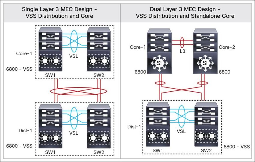
Table 1 summarizes the hardware and software revisions that are addressed in this document.

                        Table 1.        Cisco Catalyst Switches Hardware and Software Versions

                         Network Layer                   Cisco Catalyst Switch                                            Software Version
                         Distribution                    Cisco Catalyst 6800 Series Switches                              15.1(2)SY2
                         Access                          Cisco Catalyst 4500 Supervisor Engines 8-E, 7-E, and 7L-E        3.3.1.XO

                                                         Cisco Catalyst 3850/3650 Series Switches                         3.6.1.SE

                                                         Cisco Catalyst 3750-X/3560-X Series Switches                     3.6.1.SE

                                                         Cisco Catalyst 2960 S/X/XR Series Switches                       15.0.2-EX5

                        Enterprise Campus Network Design Alternatives
                        This section provides brief detailed network infrastructure guidance for each tier in the campus design model. Each
                        design recommendation is optimized to keep the network simplified and cost-effective without compromising
                        network scalability, security, and resiliency.

                        Campus Multitier Network Design Recommendations
                        The enterprise campus network deployment size and capacity vary broadly. Cisco offers a wide-ranging, rich Cisco
                        Catalyst® switching portfolio that meets precise business and technical needs of individual customer requirements.
                        With a variety of systems, offering variable port density, switching performance, scalability, and resiliency allows
                        users to design and construct an end-to-end high-performance multitier network infrastructure.

                        Figure 2.       Campus Multitier Network Deployment Models

                        Figure 2 illustrates multitier deployment models. Depending on the number of distribution-layer network blocks,
                        scale, and performance requirements, the campus can be deploy either of these models.

© 2014 Cisco and/or its affiliates. All rights reserved. This document is Cisco Public Information.                                     Page 4 of 45
As a best practice, Cisco recommends deploying a three-tier LAN design when numbers of distribution blocks are
                        greater than two. Following are the primary benefits of deploying three-tier LAN networks:

                              ●   Hierarchy:
                                  ◦ Facilitates understanding the role of each device at every tier
                                  ◦ Simplifies deployment, operation, and management
                                  ◦ Reduces fault domains at every tier
                              ●   Modularity: Allows seamless network expansion and integrated service enablement on an on-demand
                                  basis
                              ●   Resiliency: Satisfies user expectations for keeping the network always on
                              ●   Flexibility: Allows intelligent traffic load sharing by using all network resources

                        Cisco Catalyst System-Level Design Best Practices
                        The enterprise campus network size broadly varies across different verticals and industries to enable
                        communication infrastructure. The next-generation comprehensive Cisco Catalyst switching portfolio is designed to
                        meet the scale of all deployment models. It is imperative to analyze business, technical, and application
                        requirements to select the right products for unique and critical roles at different network tiers. This section
                        provides product guidance and individual system-level best practices to construct end-to-end networks with more
                        security, scalability, and resiliency.

                        Access-Layer System Design Recommendation
                        The access layer is the first tier or edge of the campus, where end devices such as PCs, printers, IP video
                        surveillance cameras, Cisco TelePresence® devices, and so on attach to the wired portion of the campus network.
                        It is also the place where IT managed devices are deployed that extend the network further out one more level,
                        such as IP phones and wireless access points connecting wired or wireless end users. The wide varieties of
                        possible types of devices that can connect and the various services and dynamic configuration mechanisms that
                        are necessary make the access layer one of the most feature-rich parts of the enterprise campus network.

                        Based on the broad range of business communication devices and endpoints, network access demands, and
                        capabilities, the following two types of access-layer design options can be deployed, as illustrated in Figure 3.

                        Figure 3.      Access-Layer System Design Alternatives

© 2014 Cisco and/or its affiliates. All rights reserved. This document is Cisco Public Information.                                        Page 5 of 45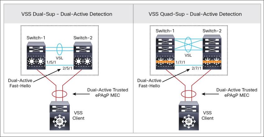
Primary Benefits: Modular/Stackable System Design

                              ●   Modular: Provides investment protection by allowing seamless wiring-closet network expansion without
                                  infrastructure change.
                              ●   Flexible: Easy integration of new network module or stack-member switch without disrupting operations.
                              ●   Resilient:
                                  ◦ Cisco Catalyst 4500E: Dual supervisor engine offers best-in-class system-level redundancy. Cisco
                                     recommended as best practices to deploy redundant supervisor to protect single-home endpoints using
                                     Stateful Switchover (SSO) technology. During planned outage such as In-Service Software Upgrade
                                     (ISSU) or abnormal supervisor failures, the network availability and capacity are fully protected for single-
                                     home devices.
                                  ◦ Cisco Catalyst 3850/3650 StackWise®: The next-generation StackWise technology supports SSO to
                                     provide protocol redundancy and forwarding state machines with distributed forwarding architecture.
                                     However, the single-home endpoints will be affected during individual failure of stack-member switches.
                                  ◦ Cisco Catalyst 3850 Cisco StackPower®: Network administrators must consider implementing power
                                     redundancy between the groups of Cisco Catalyst 3850s in a stack. The Cisco Catalyst 3850 provides
                                     nonstop forwarding even during catastrophic failures such as external power outage or the power supply
                                     unit failure.

                        Access-Layer System Redundancy Best Practices
                        The system-level redundancy support on modular versus fixed-configuration switches varies. When designed and
                        deployed based on Cisco recommended best practices, it enables resilient infrastructure to maintain network
                        communication for critical endpoint devices.

                        Supervisor and StackWise Best Practices
                        Table 2 provides best practices guidelines to deploy system-level redundancy with SSO technology on Cisco
                        Catalyst 4500Es equipped with dual-supervisor engine modules as well as on next-generation Cisco Catalyst
                        3850/3650 Series fixed-configuration switches deployed in StackWise mode.

                        Table 2.       Distribution-Layer System Resilient Best Practices

                         Best Practices                                                               Cisco Catalyst 4500/3850/3650
                         Enable SSO on Cisco Catalyst 4500E system deployed with dual                 4500E(config)#redundancy
                         supervisor engine modules (default)                                          4500E(config-red)#main-cpu
                                                                                                      4500E(config-r-mc)#mode sso
                         Enable SSO on 3850/3650 system deployed in StackWise (default)               3850-Stack(config)#redundancy
                                                                                                      3850-Stack(config-red)#mode sso

                        Cisco Catalyst 3750-X StackWise-Plus and 2960 Series platforms in FlexStack and FlexStack Plus mode do not
                        support SSO technology.

                        StackWise Software Autoupgrade Best Practices
                        The software resiliency in the Cisco Catalyst 3850/3650 is based on the Cisco IOS® Software high-availability
                        framework when these switches are stacked together in StackWise mode. These next-generation fixed-
                        configuration switches support 1+1 high-availability SSO function as modular-class platforms such as the 4500E.
                        Thus it is imperative to have consistent Cisco IOS Software and license installed on the switches of each stack-
                        member to provide 1+1 as well as N:1 ACTIVE stack system redundancy.

© 2014 Cisco and/or its affiliates. All rights reserved. This document is Cisco Public Information.                                       Page 6 of 45
If new a 3850/3650 running an inconsistent software version joins the stack ring with the current running version,
                        then such switch will force the stack ring down to an Route Processor Redundancy (RPR) state. In such a state the
                        system remains completely down.

                        As a best practice, the newly joined switch can automatically receive consistent software versions from an ACTIVE
                        switch and bring the system online without any user intervention. Table 3 illustrates simple command lines to
                        automatically download consistent software versions to newly joined switches.

                        Table 3.       Cisco Catalyst 3850/3650 Software Autoupgrade Best Practices

                         Best Practices                                                               Cisco Catalyst 3850/3650: StackWise
                         Enable software autoupgrade on Cisco Catalyst 3850/3650                      3850-Stack(config)#software auto-upgrade enable
                         StackWise switch to automatically install consistent Cisco IOS
                         Software on newly joined switch in stack ring

                        Cisco StackPower Best Practices
                        The Cisco Catalyst 3850 and 3750-X Series platform supports innovative Cisco StackPower technology to provide
                        power redundancy solutions for fixed-configuration switches. Cisco StackPower unifies the individual power
                        supplies installed in the switches and creates a pool of power, directing that power where it is needed. Up to four
                        switches can be configured in a Cisco StackPower stack with the special Cisco proprietary Cisco StackPower
                        cable. The Cisco StackPower cable is different than the StackWise data cables and is available on all Cisco
                        Catalyst 3850/3750X models. Cisco StackPower technology can be deployed in two modes:

                              ●   Sharing mode: All input power is available to be used for power loads. The total aggregated available
                                  power in all switches in the power stack (up to four) is treated as a single large power supply. All switches in
                                  the stack can provide this shared power to all powered devices connected to Power over Ethernet (PoE)
                                  ports. In this mode, the total available power is used for power budgeting decisions without any power
                                  reserved to accommodate power supply failures. If a power supply fails, powered devices and switches
                                  could be shut down. This is the default mode of operation.
                              ●   Redundant mode: The power from the largest power supply in the system is subtracted from the power
                                  budget and held in reserve. This reduces the total power available to PoE devices, but provides backup
                                  power in case of a power supply failure. Although there is less available power in the pool for switches and
                                  powered devices to draw upon, the possibility of having to shut down switches or powered devices in case
                                  of a power failure or extreme power load is reduced. Budgeting the required power and deploying each
                                  Cisco Catalyst 3850/3750-X switch in the stack with dual power supplies to meet demand are
                                  recommended. Enabling redundant mode offers power redundancy as a backup should one of the power
                                  supply units fail.

                        For better power redundancy across the stack ring, Cisco recommends deploying Cisco StackPower in redundant
                        mode as the best practice.

                        Because Cisco StackWise-480 can group up to nine 3850 Series Switches in the stack ring, Cisco StackPower
                        must be deployed with two power stack groups in order to accommodate up to four switches. The sample
                        configuration in Table 4 demonstrates deploying Cisco StackPower in redundancy mode and grouping the stack
                        members into power stack groups. To make the new power configuration effective, it is important that network
                        administrator plan for network downtime because all the switches in the stack ring must be reloaded.

© 2014 Cisco and/or its affiliates. All rights reserved. This document is Cisco Public Information.                                                     Page 7 of 45
Table 4.       Cisco Catalyst 3850/3750-X Cisco StackPower Best Practices

                         Best Practices                                                               Cisco Catalyst 3850/3650: StackWise
                         Deploy Cisco StackPower technology to provide hitless power                  3850-Stack(config)#stack-power stack PowerStack-1
                         switchover on 3850 Series Switches. Redundant mode is                        3850-Stack(config-stackpower)#mode redundant
                         recommended
                                                                                                      3850-Stack(config)#stack-power switch 1
                                                                                                      3850-Stack(config-switch-stackpower)#stack PowerStack-1

                        Cisco StackWise and FlexStack Stack-MAC Best Practices
                        To provide a single unified logical network view in the network, the MAC addresses of Layer 3 interfaces on
                        StackWise (physical, logical, Switch Virtual Interface (SVI), port channel) are derived from the Ethernet MAC
                        address pool of the master switch in the stack. All Layer 3 communication from the StackWise switch to the
                        endpoints (such as IP phones, PCs, servers, and core network system) is based on the MAC address pool of the
                        master switch.

                        The stack-mac address on Cisco Catalyst 3850/3650 Series Switches deployed in StackWise mode maintains the
                        stack-mac during ACTIVE stack switchover. By default, the stack-mac persistent timer is set to infinite, meaning do
                        not modify the MAC address of Layer 3 interface. As best practices, retaining default settings and not modifying
                        any stack-mac configuration are recommended.

                        Table 5.       Cisco Catalyst 3850/3650 and 3750X Stack-MAC Best Practices

                         Best Practices                                                               Cisco Catalyst 3850/3650: StackWise

                         Retain default stack-mac persistent setting on Cisco Catalyst                3850-Stack(config)#default stack-mac persistent timer
                         3850/3650 StackWise switches

                        By default the Cisco Catalyst 3750X StackWise-Plus and 2960 S/X/XR Series Switches do not protect the stack-
                        mac address as do the Cisco Catalyst 3850/3650. Hence, as a best practice, setting the stack-mac persistent timer
                        to zero (infinite) to prevent Address Resolution Protocol (ARP) and routing outages in the network is
                        recommended.

                        Table 6.       Cisco Catalyst 3750X and 2960-XR/S Stack-MAC Best Practices

                         Best Practices                                                               Cisco Catalyst 3750-X: StackWise
                         Modify default stack-mac persistent timer to infinite on Cisco               3750-Stack(config)#stack-mac persistent timer delay 0
                         Catalyst 3750X and 2960 S/X/XR Series Switches

                        Distribution-Layer System Design Recommendations
                        The distribution or aggregation layer is the network demarcation boundary between the Layer 2 wiring closet
                        network and the Layer 3 routed campus core network. The network operation, manageability, and application
                        performance could become very complex with traditional Layer 2 technologies such as spanning-tree. The
                        framework of the distribution-layer system must be designed with consideration of Cisco recommended best
                        practices, which significantly reduce network complexities, increase reliability, and accelerate network
                        performance. To build a strong campus network foundation with the three-tier model, the distribution layer has a
                        vital role in consolidating networks and enforcing network edge policies.

                        The next-generation fixed and modular-class Cisco Catalyst switching portfolio enables a robust scale-up and
                        scale-out networking architecture to build a high-performance infrastructure. It is imperative to analyze and deploy
                        the right set of Cisco Catalyst switching products for building a mission-critical distribution-layer system. Figure 4
                        illustrates two system-level designs for distribution-layer deployments using enterprise-class networks.

© 2014 Cisco and/or its affiliates. All rights reserved. This document is Cisco Public Information.                                                             Page 8 of 45
Figure 4.      Large Campus Distribution-Layer System Design Alternatives

                        Primary benefits: modular and extensible fixed system design:

                              ●   Modular: Provides investment protection with seamless network port and throughput expansion with
                                  multiterabit switching backplane without comprehensive infrastructure change.
                              ●   Flexible: Easy integration of new and mixed-medium network module in a switch without disrupting current
                                  network and business operations.
                              ●   Resilient:
                                  ◦ Supervisor module: Enables nonstop network communication and uncompromised performance at
                                     distribution layer. Cisco SSO technology protects business continuity during planned outages such as
                                     software upgrade in real time or in unplanned outages such as catastrophic software failures. The Cisco
                                     Catalyst 6880X supports interchassis SSO with Cisco virtual switching system (VSS) technology.
                                  ◦ Network module: Online insertion and removal procedure of network module is supported to complete
                                     new installation or migration without introducing system downtime.
                                  ◦ Power supplies: Redundant power supplies provides environmental protection in system against power
                                     outages or supply unit failures. Modular power redundancy design provides flexibility to replace swap
                                     faulty unit without introducing network downtime.
                                  ◦ Fan trays: Hot-swappable and redundant fan tray provides better cooling support and provides flexibility
                                     to replace faulty tray without introducing network downtime.

                        Alternatively, Cisco Catalyst 4500E/4500X or 3850 StackWise can be also deployed in distribution to meet the
                        needs of small to medium-size network deployments. This best practices document primarily focuses on Cisco
                        Catalyst 6800 Series systems for the distribution-layer role and providing best practices guidelines.

                        Distribution-Layer System Redundancy Best Practices
                        The Cisco Catalyst 6800 Series Switches are a leading enterprise-class high-performance and highly scalable
                        system that is broadly deployed in campus distribution-layer and core-layer roles. The Cisco Catalyst 6880X switch
                        is built upon the strong Cisco Catalyst 6500 Series Supervisor Engine 2T architecture but with a small form factor
                        that expands consistent performance and scale for network deployments in a space constraint environment.

                        Table 7 provides best practices guidelines for Cisco Catalyst 6807-XL Series Switches deployed in recommended
                        Cisco VSS mode or in traditional standalone mode and equipped with dual supervisor modules for additional
                        system-level redundancy.

© 2014 Cisco and/or its affiliates. All rights reserved. This document is Cisco Public Information.                                   Page 9 of 45
Table 7.       Distribution-Layer System Resilient Best Practices

                         Best Practices                                                               Cisco Catalyst 6800
                         Supervisor Module                                                            Dist(config)#redundancy
                         Enable SSO on system deployed with dual supervisor engine module             Dist(config-red)#main-cpu
                         (default).                                                                   Dist(config-r-mc)#mode sso
                         Network Module                                                               VSS Configuration Mode
                         Reduce higher data losses by powering down network module first prior        Dist(config)#no power enable switch [1 | 2] module [slot id]
                         to removing the module from service.
                                                                                                      Standalone Configuration Mode
                                                                                                      Dist(config)#no power enable module [slot id]
                         Power Supply Redundancy                                                      VSS Configuration Mode
                         Enable 1:1 power redundancy protection during catastrophic power             Dist(config)#power redundancy-mode switch [1 | 2] redundant
                         outage or supply unit failure (default).
                                                                                                      Standalone Configuration Mode
                                                                                                      Dist(config)#power redundancy-mode redundant

                        Distribution-Layer Network Design Recommendations
                        Distribution-Layer Network Design Alternative
                        The enterprise campus distribution-layer network can be deployed in variety of designs to meet business,
                        technical, and service needs. Most commonly it can be deployed in any of the design options as illustrated in
                        Figure 5. Depending on network designs and primary technical requirements, network architects must make
                        appropriate aggregation-layer design choices to enable end-to-end unified access network services.

                        Figure 5.      Campus Distribution-Layer Network Design Alternatives

                        All of the preceding distribution design models offer consistent network foundation services, high availability,
                        expansion flexibility, and network scalability at a system level. Each design option must be carefully evaluated to
                        compare scale, performance, operation, and resiliency requirements:

                              ●   Distribution-layer design option 1: VSS mode
                                  This deployment model is intended for large to medium-size enterprise campus network deployments using
                                  Cisco VSS technology. Cisco Catalyst 6800 enables multiterabit high-performance aggregation blocks to
                                  build nonstop communication networks without compromising user-level complexity.

© 2014 Cisco and/or its affiliates. All rights reserved. This document is Cisco Public Information.                                                              Page 10 of 45
This is the primary recommended deployment mode for distribution-layer systems.
● Distribution-layer design option 2: standalone mode
The standalone mode is the default and has been a proven mode in enterprise networks for many years.
The Cisco Catalyst 6800E system can be deployed in standalone mode with advanced fine tunings on
distribution and access-layer switches to manually construct reliable networks based on Spanning Tree
Protocol (STP). The network operation might become complex to deploy and troubleshoot when it expands
significantly.
This is a secondary recommended deployment mode for distribution-layer systems. This document does not
focus on this deployment mode.
● Distribution-layer design option 3: collapsed core/distribution mode
This deployment mode is sufficient for small campus or remote branch office networks. Any Cisco Catalyst
Series Switches can be deployed in collapsed core and distribution role to provide demarcation between
Layer 2 and Layer 3 network boundaries.
This document does not focus this deployment mode for distribution-layer systems.
Virtual Switching System Resiliency
Virtual Switching Domain and Best Practices
Domain ID Best Practices
Defining the VSS domain identifier (ID) is the initial premigration step toward implementing VSS with two
standalone physical chassis. The VSS domain ID value ranges from 1 through 255. The virtual switch domain
(VSD) includes two physical switches, and they must be configured with a common domain ID.
As a best practice, when implementing VSS in a multitier campus network design, the unique domain ID between
different VSS pairs prevents network protocol conflicts and allows for simplified network operation, troubleshooting,
and management.
Figure 6. VSS Domain ID Best Practices
© 2014 Cisco and/or its affiliates. All rights reserved. This document is Cisco Public Information. Page 11 of 45Table 8. VSS Switch Domain and ID Best Practices
Cisco Catalyst 6800: SW1 Cisco Catalyst 6800: SW2
Distribution Layer: SW1 Distribution Layer: SW2
Dist-1(config)#switch virtual domain 10 Dist-2(config)#switch virtual domain 10
Dist-1config-vs-domain)#switch 1 Dist-2(config-vs-domain)#switch 2
Core Layer: SW1 Core Layer: SW2
Dist-1(config)#switch virtual domain 20 Dist-2(config)#switch virtual domain 20
Dist-1config-vs-domain)#switch 1 Dist-2(config-vs-domain)#switch 2
VSS Switch Priority Best Practices
When the two switches boot, switch priority is negotiated to determine control-plane ownership for the virtual
switch. The virtual switch configured with the higher priority takes control-plane ownership, while the lower priority
switch boots up in redundant mode. The default switch priority is 100; the lower switch ID is used as a tiebreaker
when both virtual switch nodes are deployed with the default settings.
As a best practice, deploying both virtual switch nodes with identical hardware and software to take full advantage
of the distributed forwarding architecture with a centralized control and management plane is recommended.
Control-plane operation is identical on each of the virtual switch nodes.
Hence modifying the default switch priority is an optional setting and retains default values, as each of the virtual
switch nodes can provide transparent operation to the network and the user.
Routed MAC Best Practices
The MAC address allocation for the interfaces does not change during a switchover event when the hot-standby
switch takes over as the active switch. However, if both chassis are rebooted at the same time and the order of the
active switch changes (the old hot-standby switch comes up first and becomes active), then the entire VSS domain
uses that switch's MAC address pool. Any connected devices that do not support gratuitous ARP will be affected in
network communication until the MAC address of the default gateway/interface is refreshed or timed out.
To avoid such a disruption, Cisco recommends using the configuration option provided with the VSS in which the
MAC address for Layer 2 and Layer 3 interfaces is derived from the reserved pool. This takes advantage of the
virtual switch domain identifier to form the MAC address. The MAC addresses of the VSS domain remain
consistent with the usage of virtual MAC addresses, regardless of the boot order.
As a best practice, implementing routed MAC during the VSS migration process to avoid multiple system reboots is
recommended. If VSS is already implemented without routed MAC address, then plan for downtime to get the new
virtual MAC address effective on the next reboot cycle.
Table 9. VSS Routed MAC Best Practices
Cisco Catalyst 6800: SW1 Cisco Catalyst 6800: SW2
Distribution Layer: SW1 Distribution Layer: SW2
Dist-1(config)#switch virtual domain 10 Dist-2(config)#switch virtual domain 10
Dist-1config-vs-domain)#mac-address use-virtual Dist-2(config-vs-domain)#mac-address use-virtual
Standby Chassis Restoration Best Practices
The ACTIVE supervisor in a virtual switch will periodically update dynamic forwarding information to peer
HOT_STANDBY supervisor module and local and remote distributed forwarding card (DFC) line cards to provide
fully distributed forwarding capabilities.
© 2014 Cisco and/or its affiliates. All rights reserved. This document is Cisco Public Information. Page 12 of 45This active synchronization provides rapid switchover to alternate connected paths, which helps protect user and
application experience while the system undergoes the recovery process. The failed unit could be restoring for
service, and during reinitialization state, the modules and ports become operational before actual forwarding
information is resynchronized from the current ACTIVE switch.
Such a partial operational state of rejoined virtual switch will attract the data plane from peer devices while
forwarding information is still pending. As a result, at the network level it will introduce higher data loss in the
system recovery process than actual system loss.
As a best practice, Cisco recommends implementing a delay timer on standby chassis ports to become operational
during bootup time. With this recommendation, the standby chassis will have sufficient time to first synchronize
forwarding tables from the ACTIVE switch prior to becoming available for servicing user data from peer devices.
Table 10. VSS Routed MAC Best Practices
Best Practices Cisco Catalyst 6800: VSS
Configure standby delay timer to 300 seconds Dist(config)#switch virtual domain 10
Dist(config-vs-domain)#standby port delay 300
Dist(config-vs-domain)#standby port bringup 1 2
Virtual Switching Supervisor HA Best Practices
The Cisco VSS technology uses well-proven SSO technology to deliver supervisor module redundancy extending
beyond a single system. The next-generation Supervisor Engine 2T in the Cisco Catalyst 6800 Series VSS system
supports multidimension redundancy to protect against supervisor modules and chassis reset or failure. Figure 7
illustrates two supervisor redundancy alternatives to build simple and resilient distribution-layer networks.
Figure 7. Dual- and Quad-Sup Redundancy
● Dual-supervisor redundancy mode: This deployment is equipped with a single Supervisor Engine 2T
module on each Cisco Catalyst 6807-XL modular system. The system is limited to interchassis SSO
redundancy where it provides nonstop communication to all dual-homed connected devices. Supervisor
reset on any of the virtual switch systems will require complete chassis reset, including network modules
causing performance to reduce by half and recovery time decrease depending on reset cause, failure type,
and so on.
The fixed-configuration Cisco Catalyst 6880X in VSS mode can only support this redundancy mode
because of its system architecture.
© 2014 Cisco and/or its affiliates. All rights reserved. This document is Cisco Public Information. Page 13 of 45● Quad-supervisor redundancy mode: This deployment is applicable for two 6807-XL systems deployed
with two Supervisor Engine 2T modules per system in VSS mode. The system-level redundancy gets
quadrupled with total four Supervisor Engine 2T modules to protect network availability and capacity during
planned or unplanned network outages. This redundancy mode also offers redundancy to any single-homed
network devices connected directly to Cisco Catalyst 6807-XL VSS systems.
As a best practice, quad-supervisor redundancy mode is recommended when the business and technical
requirement demands a best-in-class resilient infrastructure to support network availability and capacity during
planned or unplanned network outage.
Virtual Switching Link Design and Best Practices
To cluster two physical chassis into a single logical entity, Cisco VSS technology enables the extension of various
types of single-chassis internal system components to the multichassis level. Each virtual switch must be deployed
with direct physical links, which extend the backplane communication boundary (known as virtual switch links
[VSLs]). VSLs can be considered Layer 1 physical links between two virtual switch nodes and are designed to
operate without network control protocols. Therefore, VSLs cannot establish network protocol adjacencies and are
excluded when building the network topology tables.
VSL Physical Link Connectivity Best Practices
The Cisco Catalyst 6807-XL or 6880X supports VSL capabilities on any supported 10G or 40G network modules.
VSL physical connectivity between two systems must be deployed with special consideration to make sure it has
the best level of redundancy to address various external or internal fault conditions. As a best practice, Cisco
recommends equally diversifying VSL fiber connections between the Supervisor Engine 2T and network module.
Figure 8 illustrates VSL connectivity best practices when a Cisco Catalyst 6800 Series system is deployed in VSS
mode.
Figure 8. Cisco VSS VSL Best Practices
VSL Capacity Planning Best Practices
Cisco VSS forwards user data plane over VSL as a last resort when a virtual switch does not find a local forwarding
path to switch the traffic. To minimize congestion on the VSL interface, as a best practice, the network
administrator must also consider VSL capacity planning. This planning should make sure the VSL interface has
sufficient aggregated bandwidth to reroute the user data plane in case of primary local path failure. These four
major factors must be considered when calculating required VSL bandwidth capacity:
● The aggregated network uplink bandwidth capacity on per virtual switch node basis, for example, 2 x 10GE
diversified to the same remote core system.
© 2014 Cisco and/or its affiliates. All rights reserved. This document is Cisco Public Information. Page 14 of 45● Designing the network with single-homed device connectivity (no multichassis EtherChannel [MEC]).
Single-homed network devices connectivity is highly discouraged.
● Remote Switched Port Analyzer (SPAN) from one switch member to another virtual switch system.
● If the 6807-XL system is deployed with integrated service module (that is, ASA-SM, WiSM2, and so on),
then depending on the service module forwarding design and capacity, the user data may be carried over
the VSL bundle.
Maximum VSL EtherChannel interface can carry up to 8 x 10G/40G ports. For optimal traffic load sharing between
VSL member links, bundling VSL member links in powers of 2 (that is, 2, 4, and 8) is recommended.
VSL Redundancy Best Practices
The VSL EtherChannel functions as an extended backplane link that enables system virtualization by transporting
interchassis control traffic, network control plane, and user data traffic. The state machine of the unified control-
plane protocols and distributed forwarding entries gets dynamically synchronized between the two virtual switch
nodes. Any fault triggered on a VSL component breaks the system virtualization and introduces a dual-active
condition into the network. Figure 9 illustrates two techniques to detect such fault conditions and rapidly recover the
system before the network and end-user applications are affected.
Figure 9. Dual Active Detection Best Practices
● Dual active fast hello best practices:
◦ Up to four ports of any link type and speed can be used to pair up for dual active fast hello detection.
Minimum one port is recommended.
◦ Dual-active fast hello is supported on supervisor and network module ports. For dual-sup network design,
onboard supervisor 1G port can be used for fast hello. For quad-sup network design one of the available
ports from network module should be selected for better redundancy during failure of either supervisor
module.
◦ Dual-active fast hello can coexist with enhanced Port Aggregation Protocol (ePAgP). Having both
mechanics implemented for better redundancy is recommended.
© 2014 Cisco and/or its affiliates. All rights reserved. This document is Cisco Public Information. Page 15 of 45Table 11. Implementing Dual Active Fast Hello
Cisco Catalyst 6800: VSS
Dist(config)#interface range Gig 1/3/1, Gi2/3/1
Dist(config-if-range)#dual-active fast-hello
● Enhanced PAgP+ best practices:
◦ Large number of Layer 2 or Layer 3 PAgP-enabled EtherChannels can be used for dual-active detection
method. Minimum of two dual-active trusted MECs is recommended for better redundancy.
◦ Trusted Layer 2 MEC could be an access-layer switch. Layer 3 MEC could be a core-layer switch. Both
can coexist and are recommended.
◦ Enabling or disabling dual-active trust setting on Layer 2 or Layer 3 requires interfaces to be in
administrative shutdown state. Hence, as a best practice, planning a short downtime to implement the
solution is recommended.
Table 12. VSS Dual-Active Trust on PAgP MEC Best Practice
Cisco Catalyst 6800: VSS Dual-Active PAgP VSS Client
Dist(config)#interface range Port-Channel 101-102 No configuration required
Dist(config-if-range)#shutdown
Dist(config)#switch virtual domain 1
Dist(config-if-range)#dual-active detection pagp trust channel-group 101
Dist(config-if-range)#dual-active detection pagp trust channel-group 102
Dist(config)#interface range Port-Channel 101-102
Dist(config-if-range)#no shutdown
● Dual active exclude best practices:
◦ During dual active state the recovery chassis automatically disables all ports to prevent network
malfunction. As a best practice it recommended to exclude the Layer 3 out-of-band management port
from each virtual switch chassis to remain operational for additional troubleshooting and debugging.
◦ Any management port can be used from supervisor and network modules. For dual-sup network design
onboard supervisor 1G port can be used. For quad-sup network design an available port from network
module should be selected for better redundancy during failure of either supervisor module.
◦ These excluded management ports must be reachable through separate Layer 2/Layer 3 network
infrastructure instead from core routing space.
◦ The static route from each Layer 3 excluded interface would be required to reach network beyond local
subnet.
Table 13. VSS Dual-Active Trust Exclude Interface Best Practices
Cisco Catalyst 6800: VSS
Dist(config)#interface Gig1/3/2
Dist(config-if)#ip address
Dist(config-if)#no shutdown
Dist(config)#interface Gig2/3/2
Dist(config-if)#ip address
Dist(config-if)#no shutdown
© 2014 Cisco and/or its affiliates. All rights reserved. This document is Cisco Public Information. Page 16 of 45Cisco Catalyst 6800: VSS
Dist(config)#switch virtual domain 1
Dist(config-if-range)#dual-active exclude interface Gi1/3/2
Dist(config-if-range)#dual-active exclude interface Gi2/3/2
Dist(config)#ip route
Dist(config)#ip route
System and Network Connectivity Best Practices
Campus Network Oversubscription Best Practices
The switching performance demands can be combined with the scale factors at every network layer. Most large
enterprise campus networks in multitier architectures are oversubscribed. The network expansions at the edge
always demanded refreshing campus core switching capacity, but it is becoming increasingly challenging to
maintain oversubscription ratios with prolific 10G use in next-generation wiring-closet networks. The high-speed
switching capacity demands are fueled by several reasons: new devices such as 1G desktop, wireless 802.11AC,
video, mobile device proliferations, and so on. To maintain consistent quality of experience (QoE) with increased
scale and performance demands, IT needs to reevaluate two major bottleneck points in campus networks. These
bottlenecks are at the campus distribution layer that aggregates 10G physical connection and core switching
capacity to maintain 4:1 oversubscription ratios.
As a best practice, to mitigate campus and data center core scale and performance challenges and to protect 4:1
oversubscription ratios, the 40G Ethernet innovations in Cisco Catalyst 6800-E and Cisco Nexus® 7000 systems
allow easy and seamless upgrade from existing 10G-based core infrastructure. The distribution layer should
maintain a 20:1 oversubscription ratio in distribution-access networking blocks. If the access-layer switches in
Intermediate Distribution Frame (IDF) are increasing capacity by tenfold, then network architects must make sure
that aggregation switches, modules, and ports are able to meet the required performance. In modular distribution-
layer design, the leading Cisco Catalyst 6800 Series system can be deployed with next-generation Supervisor
Engine 2T with Cisco Catalyst 6904 or 6816 line-card modules for 10G port aggregations.
Figure 10. Network Oversubscription Best Practices
© 2014 Cisco and/or its affiliates. All rights reserved. This document is Cisco Public Information. Page 17 of 45Access-Layer Network Connectivity Best Practices
The uplink network connectivity design from a variety of access-layer model switches to distribution-layer systems
is critically important for optimizing application performance and network resiliency. This best practice makes sure
the user data plane is well load balanced to optimally utilize all system resources and that network protocols are
building redundant forwarding paths to rapidly switch over during various types of planned and unplanned network
outages.
Cisco Catalyst 4500-E Redundant Supervisor Uplink Recommendation
In redundant mode, the Cisco Catalyst 4507R+E or 4510R+E chassis is deployed with dual Supervisor Engine 8-E
or 7-E modules in a redundant SSO configuration. The four 1G/10G uplink ports on each supervisor module are
divided into two port groups: port group 1 (port 1 and 2) and 2 (port 3 and 4). Port group 2 becomes automatically
inactive on both supervisor modules when the Cisco Catalyst 4500E system detects redundant modules installed in
the chassis.
As illustrated in Figure 11, as a best practice, utilize all four uplink ports from both supervisors to a redundant Cisco
Catalyst 6800 Series distribution-layer VSS system. Both supervisor modules can equally diversify port group 1
with the redundant upstream system for the same consistent bandwidth capacity, load balancing, and link
redundancy as nonredundant mode.
Figure 11. 4500-E Redundant Supervisor Uplink Recommendations
Cisco StackWise and FlexStack Uplink Recommendation
Cisco Catalyst 3850/3650, 3750-X, and 2960 Series Switches support up to 4 physical uplink ports to connect
distribution-layer switches. Typically up to 2 physical uplink interfaces are deployed from access-layer switches for
optimal load balancing and redundancy in the wiring closet.
When these switches are deployed in stack configuration mode, maintaining the same uplink connection design
principle as with a dual stack-member system is recommended. For example, nine Cisco Catalyst 3850 switches
deployed in a stack ring would have 2 diversified uplink ports from switch 1 and 2 diversified uplink ports from
switch 9. The remaining seven switches forward the data toward the core using a high-speed stack backplane.
This recommended uplink port design offers various benefits, from application performance to optimal user
experience:
● Improved application performance by increasing aggregated stack switching capacity with multiple
distributed high-speed 10Gbps uplinks between stack member Cisco Catalyst switches
© 2014 Cisco and/or its affiliates. All rights reserved. This document is Cisco Public Information. Page 18 of 45● Enhanced bidirectional traffic engineering with intelligent network data load sharing within the stack ring and
across all distributed uplink physical ports
● Improved system and application performance by utilizing the distributed forwarding architecture advantage
of hardware resources: buffers, queues, ternary content-addressable memory (TCAM), and so on.
● Protection of stack and network-level redundancy and minimization of congestion between distributed
aggregation systems caused during a major outage at the access or distribution layer
Figure 12. Cisco StackWise and FlexStack Uplink Recommendations
Cisco StackWise and FlexStack Switch Priority Recommendation
Cisco introduced various generations of StackWise and FlexStack technologies on different generations of
switching portfolio. Every new generation of this technology offered advanced capabilities to optimize scale,
performance, and resiliency while maintaining simplicity to the user and network.
The stack technology simplicity is attained by centralizing control and management planes from all stack-member
switches to a dynamically elected single switch in a ring. The switching performance is optimized by building a fully
distributed forwarding architecture to optimally utilize through stack backplane and all diversified system resources
such as uplink fiber ports, TCAM, and so on.
As a best practice, decoupling the control and management-plane operation with uplink port operation in
StackWise and FlexStack switches is imperative. This can be achieved by statically assigning switch IDs for each
stack-member switch. The switch with higher priority is deterministically elected for ACTIVE/master role in a stack
ring. For rapid reelection, a secondary switch can be preset with the next lower priority level. This best practice
reduces network reconvergence time when the ACTIVE/master switch fails in the stack.
© 2014 Cisco and/or its affiliates. All rights reserved. This document is Cisco Public Information. Page 19 of 45Figure 13. Cisco StackWise and FlexStack Switch Priority Recommendations
Table 14 provides best practices configuration to statically configure switch priority on Cisco Catalyst 3850/3650,
3750-X, and 2960 Series Switches.
Table 14. Cisco StackWise Switch Priority Best Practices
Cisco Catalyst StackWise and FlexStack Switch Cisco StackWise and FlexStack Switch Priority
3850-Stack#switch 1 priority 1 3750X-Stack#config terminal
! Switch 1 with Uplink ports 3750X-Stack(config)#switch 1 priority 1
3850-Stack#switch 2 priority 11 ! Switch 1 with Uplink ports
3850-Stack#switch 3 priority 12 3750X-Stack(config)#switch 2 priority 11
3850-Stack#switch 4 priority 13 3750X-Stack(config)#switch 3 priority 12
3850-Stack#switch 5 priority 15 3750X-Stack(config)#switch 4 priority 13
3850-Stack#switch 6 priority 14 3750X-Stack(config)#switch 5 priority 15
3850-Stack#switch 7 priority 10 3750X-Stack(config)#switch 6 priority 14
3850-Stack#switch 8 priority 9 3750X-Stack(config)#switch 7 priority 10
3850-Stack#switch 9 priority 2 3750X-Stack(config)#switch 8 priority 9
! Switch 9 with Uplink ports 3750X-Stack(config)#switch 9 priority 2
! Switch 9 with Uplink ports
Table 15. Cisco FlexStack Switch Priority Best Practices
Cisco Catalyst StackWise and FlexStack Switch Cisco StackWise and FlexStack Switch Priority
2960XR-Flex#config terminal 2960S-Flex#config terminal
2960XR-Flex(config)#switch 1 priority 1 2960S-Flex(config)#switch 1 priority 1
! Switch 1 with Uplink ports ! Switch 1 with Uplink ports
2960XR-Flex(config)#switch 2 priority 11 2960S-Flex(config)#switch 2 priority 14
2960XR-Flex(config)#switch 3 priority 12 2960S-Flex(config)#switch 3 priority 15
2960XR-Flex(config)#switch 4 priority 13 2960S-Flex(config)#switch 4 priority 2
2960XR-Flex(config)#switch 5 priority 15 ! Switch 4 with Uplink ports
2960XR-Flex(config)#switch 6 priority 14
2960XR-Flex(config)#switch 7 priority 10
2960XR-Flex(config)#switch 8 priority 2
! Switch 8 with Uplink ports
© 2014 Cisco and/or its affiliates. All rights reserved. This document is Cisco Public Information. Page 20 of 45Distribution-Layer Network Connectivity Best Practices
The campus distribution and core-layer systems typically have modular hardware with centralized processing on a
supervisor module and distributed forwarding on high-speed network modules. The fundamentals of building a
resilient campus network design with diversified, distributed, and redundant physical paths do not vary by role,
system, or deployed configuration mode. The physical uplink connection from each distribution layer to the core
can be with single or dual uplink Layer 3 interfaces. The single link builds a square physical topology that does not
offer optimal load balancing and redundancy. It also affects application performance with slower network recovery
during planned system or network-level failures.
Following common physical-layer network design principles as a best practice, Cisco recommends deploying full-
mesh redundant physical connections at any level of network tiers as illustrated in Figure 14.
Figure 14. Full-Mesh Distribution Core-Layer Connectivity Best Practices
Cisco Multi-Chassis Layer 2 EtherChannel Best Practices
Traditionally campus networks were designed with standalone network systems and equal cost multipath (ECMP),
which did not provide the flexibility to simplify network design with redundant devices or paths to logically act as a
single entity. Campus network designs are evolving with Cisco's system virtualization innovation in Cisco Catalyst
switching platforms, such as VSS, StackWise, and FlexStack, with redesign opportunities in all three tiers. While
each of these virtualization techniques clusters multiple physical systems into a single large and unified logical
system, the distributed multiple parallel physical paths can now be bonded into logical point-to-point EtherChannel
interfaces between two systems. The principle of building a full-mesh physical campus network should not be
changed when a campus device or link is implemented to operate in logical mode.
Designing a multilayer or campus backbone network with EtherChannel between two systems offers multiple
benefits:
● Simplify: Bundling multiple ECMP paths into logical EtherChannel reduces redundant protocol adjacencies,
routing databases, and forwarding paths.
● Optimize: Reduces the number of control-plane operations and optimizes system resources, such as
CPU/memory utilization. Provides flexible Layer 2 to Layer 4 variables to intelligently load share and utilize
all resources for network data traffic across each bundled interface.
© 2014 Cisco and/or its affiliates. All rights reserved. This document is Cisco Public Information. Page 21 of 45You can also read