CFD SIMULATION FOR REDUCTION THROMBOSIS IN BILEAFLET MECHANICAL HEART VALVE USING VORTEX GENERATORS
←
→
Page content transcription
If your browser does not render page correctly, please read the page content below
Journal of Engineering Science and Technology
Vol. 16, No. 3 (2021) 2736 - 2747
© School of Engineering, Taylor’s University

 CFD SIMULATION FOR REDUCTION
 THROMBOSIS IN BILEAFLET MECHANICAL
 HEART VALVE USING VORTEX GENERATORS

 NURSYAIRA MOHD SALLEH1,
 MOHAMAD SHUKRI ZAKARIA1,2,*, MOHD JUZAILA ABD LATIF1,3
 1Fakulti Kejuruteraan Mekanikal, Universiti Teknikal Malaysia Melaka,
 Hang Tuah Jaya, 76100 Durian Tunggal, Melaka, Malaysia
 2Centre for Advanced Research on Energy, Universiti Teknikal Malaysia Melaka,

 Hang Tuah Jaya, 76100 Durian Tunggal, Melaka, Malaysia
 3Advanced Manufacturing Centre, Universiti Teknikal Malaysia Melaka,

 Hang Tuah Jaya, 76100 Durian Tunggal, Melaka, Malaysia
 *Corresponding Author: mohamad.shukri@utem.edu.my

 Abstract
 Present study was done to investigate the performance of steady state flow
 through bileaflet mechanical heart valve (BMHV) with fixed fully open leaflet
 that equipped with vortex generator (VG) by using computational fluid
 dynamic (CFD) method. The VGs as a passive flow device that can improve
 the pressure gradient and reducing turbulent are investigated. For better
 understanding, the implications that VGs has on the blood flow through these
 valve, analysis of flow characteristic such as velocity and pressure drop was
 performed. The novelty of this study is to determine the performance of VGs
 configurations affect the computed velocity and pressure gradient associated
 with the development of the blood clotting. The laminar flow cases that
 computed mean velocity profile are done validate close to the experimental
 result. Results suggested that triangular VGs caused increase velocities and
 reduce pressure drop. The straight triangular VGs showed lower pressure drop
 and 5.3% improvement in pressure drop. percentage.
 Keywords: Bi-leaflet mechanical valves, Computational fluid dynamics, Pressure
 drop, Thrombosis, Vortex generator.

 2736
CFD Simulation for Reduction Thrombosis in Bileaflet Mechanical Heart . . . . 2737

1. Introduction
Complications arise when using artificial prosthetic heart valves, such as
bioprosthetic heart valve or mechanical heart valve (MHV), as replacement in heart
valve diseases. The most common replacement used in the world is bileaflet
mechanical heart valve because their design can minimize flow disturbance
(BMHV) [1]. However, replacing BMHV causes major complications, such as
thrombosis (blood clotting) and bleeding, even though the design of BMHV already
been improved [2]. Warfarin is a medicine that can treat blood clotting, but this
medicine should be taken at the right dosage to prevent the development of
haemorrhage [3]. The medicine may change the lifestyle of the patient which they
will encounter a problem when injured or requires surgery especially during the
surgery it will cause excessive bleeding if not control the dosage of medicine.
 The problem with blood clotting also can be treated by using vortex generator
(VGs) as a passive flow device which can control the non-physiological flow in the
vicinity of heart valve. Therefore, the analysis of non-physiological flow through
BMHV are important to determine blood cell damage because it will initiate
thrombus formation [4]. Ge et al. [5] investigated the numerical simulation of
instantaneous limiting streamlines, contours of wall shear stress magnitude along
the sinus wall and velocity field which are not available by experimental methods.
Then they used detached eddy simulation (DES) approaches to reveals the
unknown features of the flow that it is potential as a powerful modeling tool of
cardiovascular flows at physiological conditions.
 Thrombosis complication can be reduced by converting the valves into
thrombus-resistant materials or adding a vortex generator (VG) on the leaflet to
lessen the use of warfarin. Previous study analysed the blood material interactions
rendering a BMHV with superhydrophobic coating. Bark et al. [6] explored ways
of superhydrophobic coating experiment with a receding contact angle of 160º
strikingly could eliminates platelet and leukocyte adhesion to the surface.
Superhydrophobic BMHV has the potential to relax the requirement for antiplatelet
and anticoagulant drug regimens typically required for patients receiving MHVs by
minimizing blood-material interaction. Another study investigated passive flow
control device that applied to BMHV could optimizes leakage flow hemodynamics
at length scales that relevant to blood damage and platelet activation [7, 8].
 Dasi et al. [7] analysed rectangular and hemispherical VG using particle high
velocimetry (PIV) technique under pulsatile and steady flow condition. This study
presents the significant diminution of turbulence stresses, specifically with the
rectangular VG configuration. Then, Hatoum et al. [8] reported that rectangular VG
configuration under pulsatile flow condition using PIV technique could improve
pressure gradient and reducing turbulent. This study using rectangular VGs through
different arrangement to generate a more delayed flow separation and more
homogenized, streamline transition of flow. The application of VGs as a passive
flow device in heart valve replacement contribute for controlling the development
of blood clots by improving the hemodynamics of the valve.
 The objective of this study is to investigate the performance of blood flow through
BMHV at different level of triangular VGs configuration by reporting the relevant
flow structure using contour and vector information, calculating the changes of
pressure drop and comparing the result of pressure drop with triangular VGs
configuration. The numerical simulation was performed on SJM valve model as a

Journal of Engineering Science and Technology June 2021, Vol. 16(3)

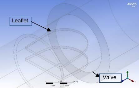
2738 N. M. Salleh et.al

prosthetic replacement for the aortic heart valve as shown in Fig. 1. In current study,
Computational Fluid Dynamics (CFD) is used to model the valves and blood flows
as the software allows relatively easy and economical conduction of parametric
studies. This study also could provide data that can enhance our understanding of the
VGs application which can lead to improve the design of MHV.

 Housing Suture ring

 Leaflet

 Fig. 1. The St. Jude Medical (SJM) valve model [6].

2. Numerical Method
The numerical method that used to develop the SJM valve laminar flow pattern was
performed by solving the Navier-Stokes equation. The equation provides
information on instantaneous velocity and pressure distribution. The application to
solving the equation in medical field was previously used extensively in solving in
other engineering area such as wind turbine [9], pipe flow [10], hydraulic [11], etc.
The equations discuss the Navier-Stokes equations in differential form that
obtained by using an infinitesimal control volume moving along a streamline with
 �⃗ = ( , , ) equal to the flow velocity at each point. For the three-
velocity vector
dimensional incompressible flow, the continuity in Eq. (1) and three momentum
equation is shown in Eqs. (2) to (4) [12].

 + + =0 (1)

 =− +� + + � + (2)

 =− +� + + � + (3)

 =− +� + + � + (4)

where Eq. (1) is the continuity equation, and Eqs. (2), (3) and (4) are momentum
equations in y. In equation above, is the density of fluid, D/Dt is the material
derivative and is a pressure that present in a fluid at rest and acts normal to a
surface and viscous stress which act normal to a surface or tangentially (shear
stress). The pressure drop value can be calculated by identifying the pressure
value in the simulation result. The pressure drop equation is non-dimensional ∆P
coefficient equation, as shown in Eq. (5).
 1
∆ = �( 1 − 2 )/( 2 )� (5)
 2

where V is the average velocity, P1 is the pressure at the leading edge of the leaflet,
P2 is the pressure at trailing edge of the leaflets and ρ is the blood density.

Journal of Engineering Science and Technology June 2021, Vol. 16(3)
CFD Simulation for Reduction Thrombosis in Bileaflet Mechanical Heart . . . . 2739

Numerical geometry
The geometry of the SJM valve as a prosthetic replacement for the aortic heart valve
is shown in Fig. 2, with an inlet and outlet diameter of 25.4 mm representing the
idealized aortic sinus root [2, 5]. The geometric model using aortic root contained a
single axisymmetric sinus. The SJM valve has an orifice internal diameter of 20.4
mm and is geometrically identical to the prostheses implanted to the patients. The
leaflet of the valve is fully open at an angle of 85° along the y-z plane.

 (a) (b)
 Fig. 2. Numerical geometry: (a) plan view of streamwise vertical
 axis at three different locations (F1-F3) and (b) geometry of SJM valve.

 The VG geometry with triangular shape mounted on the downstream side of
SJM valve with different arrangements was chosen in this study. Figure 3 shows
the two different VG arrangements where the model of the valve is designed using
Solidwork 2018. The base VG dimensions were chosen to be 1 mm of thickness,
height 1 mm and length 4 mm based on Hatoum et al. [8].

Flow direction Flow direction

 (a) (b)
 Flow direction

 (c)

 Fig. 3. VG leaflet arrangement: (a) equally triangular
 VG (b) straight triangular VG (c) triangular VG dimension.

Journal of Engineering Science and Technology June 2021, Vol. 16(3)
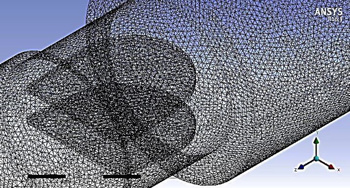
2740 N. M. Salleh et.al

 For the meshing process, the maximum value of the skewness is ideally less than
0.85 [13]. For this study, the number of nodes 482K and elements 2M provide
maximum value of skewness is 0.83 that show it is good quality of meshing. This
study used a mesh configuration with tetrahedron shape. This configuration has a
maximum mesh size of 0.0004 m. This method was used to assure that the mesh
configuration can produce good simulation result. The mesh configuration of the
geometry is shown in Fig. 4, by using ANSYS meshing application.

 Fig. 4. Mesh configuration of SJM valve.

 Figure 5 shows the grid-independent test study of the SJM valve for steady state
solution at Re = 750. The velocity in stream-wise direction at the downstream of
the leaflet at central plane (x = 0 mm) was computed (see Fig. 6, for plotted
location). The velocity profile becomes grid-independent with increasing total
number of elements [14]. Although choosing a large grid number 1.3 M is
sufficient, the model with 1.08 M was chosen for mesh generation due to slight
difference in the velocity profile.

 Fig. 5. Grid independent test.
 The fluid used in the simulation had a density of 1060 kg/m3 and dynamic
viscosity of 5.5×10⁻³ kg/ms [5]. The boundary conditions were set with inlet, outlet
and wall domain at the geometry as following.

Journal of Engineering Science and Technology June 2021, Vol. 16(3)
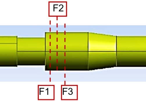
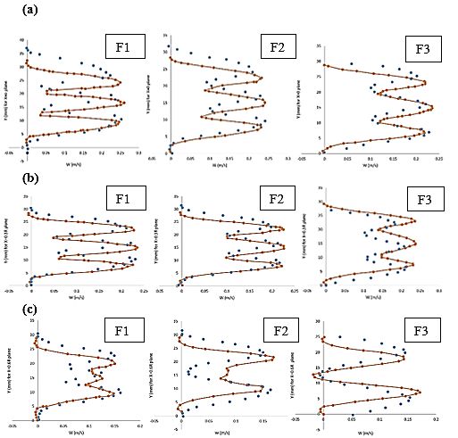
CFD Simulation for Reduction Thrombosis in Bileaflet Mechanical Heart . . . . 2741

 At the inlet of the domain, the velocity inlet, V (m/s) was set with user-defined
function (UDF) at the center of the z-plane. The inlet boundary conditions were
assumed according to the parabolic profile in the boundary layer by setting the
velocity profile to compute the non-uniform velocity distribution at the inlet.
 Reynolds number is defined as Re = VavgD/v, where D is the inlet diameter,
is the kinematic viscosity and Vavg is the average velocity [6]. The reference
inlet was set at a fully developed velocity with Vavg = 2/3Vmax and 25.4 mm of
inlet diameter.
 The radius from the central axis of parabola was calculated using Eq. (6). The
parabolic inlet boundary equation was derived as a velocity profile equation in
Eq. (7).
 = �( [0] − 0 )2 + ( [1] − 0 )2 + ( [2] − 0 )2 (6)
 2
 = �1 − � � � (7)

where r is the radius from central axis of parabola, and R is the maximum radius of
the valve.
 A pressure outlet in the domain was applied with a pressure gauge of zero
pascal because of the same effect generated by the difference in fluid distribution
function in the flow [15]. The domain wall was set to no-slip shear condition
because the wall motion is stationary.
 The discretization scheme was a phase-coupled Semi-Implicit Method for
Pressure Linked Equations (SIMPLE) for pressure-velocity coupling in the Navier
stokes equation, least square cell based for the gradient, second order for pressure
and second order upwind for momentum. The solution control was 0.3 for pressure
and 0.7 for momentum under relaxation factors. The convergence criteria were set
to 1x10⁻⁶ to achieve the convergence. The calculation was computed until reaching
the steady state.
 There are several assumptions that are made by simplifying the fundamental
equations in order to approximate blood flow characteristic of the domain. The
assumption for blood flow through BMHVs are incompressible fluid with constant
density that assumed to behave as Newtonian fluid [16]. This is because the main
constituent of blood is the plasma where it is has properties of Newtonian fluid that
the shear rate is linear, then this assumption is considered valid [17].

3. Validation and Verification
The numerical method was validated to determine the accuracy and ability of the
method to produce accurate flow physics. The results were compared with the
available experimental data [5]. The capabilities of the model were compared in
Fig. 6. The graph was found in computed steady state condition with stream-wise
velocity profiles (physical velocity) and three different locations (F1-F3) shown in
Fig. 2, at different planes parallel to the leaflet (central planes, 0.3R mm and 0.6 R)
for the Re = 750 case. The 25.4 mm value of R referred to the radius of the inlet
diameter for SJM valve. The root mean square (RMS) is calculated to quantify the
difference between computational and experimental results. The RMS of the
velocity profile difference was 2.5% of the maximum velocity.

Journal of Engineering Science and Technology June 2021, Vol. 16(3)

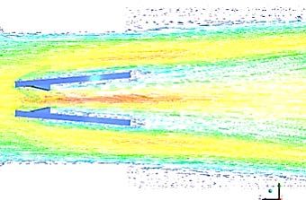
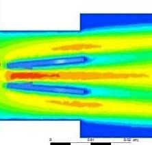
2742 N. M. Salleh et.al

 Fig. 6. Velocity profile comparison between previous study and CFD
 method for (a) X=0 (b) X=0.3R mm (c) X=0.6R mm plane position
 (previous study – PIV [4, 5], Present CFD method).

 The graph showed that the numerical simulation was essentially accurate in
all features observed in the experiment. The complex transverse distribution of
the momentum within the cross section and the rate at which the three jets diffuse
and merge in stream-wise direction.

4. Results and Discussion
The numerical simulation for laminar flow regime at Re = 750 was conducted with
the SJM valve at a fully open position. This study aimed to investigate and
understand the effect of using VG as a method in reducing blood clots. Validating
the numerical method is essentially important to achieve accurate flow physics. The
laminar flow regimes were repeated with different triangular VG arrangements to
obtain the pressure losses with and without VG. Figure 7 shows the velocity contour
and vector for the different arrangements of triangular VGs. The instantaneous
stream-wise velocity at x=0 plane (symmetry plane perpendicular to the leaflets).
The highest max velocity among VG arrangement was found in an equally
triangular VG at 0.291 m/s, followed by straight triangular VG at 0.286 m/s and
without VG at 0.282 m/s. A velocity with a smaller value could lead to blood
clotting [18]. For straight triangular VG, the blood flow seemed to have a uniform
velocity compared to the equally triangular VG.

Journal of Engineering Science and Technology June 2021, Vol. 16(3)
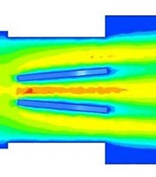
CFD Simulation for Reduction Thrombosis in Bileaflet Mechanical Heart . . . . 2743

 Contour Vector

 (a) Without VG

 (b) Straight triangular VG

 (c) Equally triangular
 Fig. 7. Velocity contour and vector for
 VG leaflet at different arrangements of VGs.

 Moreover, the velocity vector is responsible for the combination of vortex
shedding where the wake is produced at the trailing edge of VGs [19]. The direction
of the blood flow within sinuses and from leaflet could determine from velocity
vector representation [20]. The vortex normally encountered in the bluff body and
sharp edge due to inertia. The detail analysis through computational study can
improve the design of MHV which is the vortices can be reduced then the blood
clotting can be prevented [21]. Figure 8 shows the velocity profile comparison of
triangular VGs configuration. The blood flow through BMHV without VG seemed
to have non-uniform velocity than having VGs.
 The effect of using triangular VG with different arrangements can be measured
by calculating the non-dimensional ∆P coefficient equation to find pressure loss
through VGs. The identification of the location of the inlet and outlet pressures are
shown in Fig. 9. The pressure drop value was identified by using Fig. 9, as a guide
for obtaining the value of pressure loss. The pressure drops were calculated to
determine the value of decreasing blood clots. The pressure losses were calculated
with and without triangular VG. The values of inlet and outlet pressures were
collected from the numerical simulation under steady state conditions.

Journal of Engineering Science and Technology June 2021, Vol. 16(3)
2744 N. M. Salleh et.al

 35

 30

 25
 without VG
 20
Y (mm)

 15 straight triangle
 VG
 10 equally triangle
 VG
 5

 0
 -0.1 0 0.1 0.2 0.3
 W (m/s)

 Fig. 8. Velocity profile comparison with VG ( without VG
 ---- straight triangular VG equally triangular VG)

 P1 P2

 Fig. 9. Pressure drop, ∆ = −

 Table 1 demonstrates that less pressure drop across the heart valves indicates
the small obstruction area. Therefore, a good efficiency of the heart valve can be
obtained. The blood flow through vessel or across the heart valve have a force
propelling the blood which this force is the difference in blood pressure. The result
of pressure drop tended to increase from 0% to 5.3% with straight triangular VG
and 2.7% for equally triangular VG. The development of blood clotting increases
with increasing pressure drop. A similar phenomenon occurs with increasing
velocity. The rotating motion of blood particles increases at the same spot, and the
probability of blood accumulation reduce thrombus development.

 Table 1. Data for the pressure drop.
 Without VG Straight triangular VG Equally triangular VG
 P1 24.5699 Pa 24.041 Pa 24.526 Pa
 P2 10.059 Pa 10.303 Pa 10.402 Pa
 ∆ 1.165 1.103 1.134
 Percentage, % 0 5.3% 2.7%

Journal of Engineering Science and Technology June 2021, Vol. 16(3)
CFD Simulation for Reduction Thrombosis in Bileaflet Mechanical Heart . . . . 2745

5. Conclusions
In this study, the blood flow through BMHV is analysed at different arrangement of
triangular VGs. Results suggested that using VGs could affect the performance of
BMHV flow. For instance, as BMHV equipped with triangular VGs, the maximum
velocity magnitude increases from 0.25 m/s to 0.28 m/s in the middle for straight
triangular VGs configuration. Higher velocities and flow separation at the leaflet
surface were accompanied by growing eddies and vorticity downstream of the valve.
The pressure drop was found to increase from 0% to 5.3% for straight triangular VGs.
Even though pulsatile flow, turbulent flow and motion of the leaflets were not
considered in this paper, the study comprises an important step toward the
development of a numerical simulation structure for MHV flows. This study also
yielded a validated and reliable flow solver, which can help further investigation to
tackle the next level complexity. Therefore, further studies are needed in improving
the method or geometry to obtain satisfactory results.

Acknowledgement
The authors thank to the Universiti Teknikal Malaysia Melaka (UTeM) and the
Ministry Education Malaysia (MOE) for funding this research project through
grants no: FRGS/2018/FKM-CARE/F00367 and Faculty of Mechanical
Engineering at UTeM for its practical support.

 Nomenclatures
 D Diameter of the valve, mm
 Re Reynolds number
 r Radius of valve, mm
 �⃗
 Velocity vector, m/s
 Vavg Average velocity, m/s
 Vmax Maximum velocity, m/s
 ∆P Pressure drop, Pa

 Abbreviations
 BMHV Bileaflet Mechanical Heart Valve
 CFD Computational Fluid Dynamics
 NS Navier-Stokes
 RMS Root mean square
 SIMPLE Semi-Implicit Method Pressure Linked Equations
 VG Vortex Generator

References
1. Dasi, L.P.; Simon, H.A.; Sucosky, P.; and Yoganathan, A.P. (2009). Fluid
 mechanics of artificial heart valves. Clinical Experimental Pharmacology and
 Physiology, 36(2), 225-237.
2. Yun, B.M.; Wu, J.; Simon, H.A.; Arjunon, S.; Sotiropoulos, F.; Aidun, C.K.;
 and Yoganathan, A.P (2012). A numerical investigation of blood damage in
 the hinge area of aortic bileaflet mechanical heart valves during the leakage
 phase. Annals of Biomedical. Engineering, 40(7), 1468-1485.

Journal of Engineering Science and Technology June 2021, Vol. 16(3)
2746 N. M. Salleh et.al

3. Zakaria, M.S.; Ismail, F.; Tamagawa, M.; Aziz, A.F.A.; Wiriadidjaja, S.; Basri,
 A.A.; and Ahmad, K.A. (2017). Review of numerical methods for simulation of
 mechanical heart valves and the potential for blood clotting. Medical Biological
 Engineering Computing, 55, 1519-1548.
4. Yun, B.M.; Dasi, L.P.; Aidun, C.K.; and Yoganathan, A.P. (2014).
 Computational modelling of flow through prosthetic heart valves using the
 entropic lattice-Boltzmann method. Journal of Fluid Mechanics, 743, 170-201.
5. Ge, L.; Leo, H.L.; Sotiropoulos, F.; and Yoganathan, A.P. (2005). Flow in a
 mechanical bileaflet heart valve at laminar and near-peak systole flow rates:
 CFD simulations and experiments. Journal Biomechanical Engineering,
 127(5), 782-797.
6. Bark Jr, D.L.; Vahabi, H.; Bui, H.; Movafaghi, S.; Moore, B,; Kota, A.K.;
 Popat, K.; and Dasi, L.P. (2017) Hemodynamic performance and
 thrombogenic properties of a superhydrophobic bileaflet mechanical heart
 valve. Annals Biomedical Engineering, 45(2), 452-463.
7. Dasi, L.P.; Murphy, D.W.; Glezer, A.; and Yoganathan, A.P. (2008). Passive
 flow control of bileaflet mechanical heart valve leakage flow. Journal
 Biomechanics, 41(6), 1166-1173.
8. Hatoum, H.; and Dasi, L.P. (2019). Reduction of pressure gradient and
 turbulence using vortex generators in prosthetic heart valves. Annals of
 Biomedical Engineering, 47(1), 85-96.
9. Sudhamshu, A.R.; Pandey, M.C.; Sunil, N.; Satish, N.S.; Mugundhan, V.; and
 Velamati, R.K. (2016). Numerical study of effect of pitch angle on
 performance characteristics of a HAWT. Engineering Science Technology an
 International Journal, 19(1), 632-641.
10. Dutta, P.; Saha, S.K.; Nandi, N.; and Pal, N. (2016). Numerical study on flow
 separation in 90° pipe bend under high Reynolds number by k-ε modelling.
 Engineering Science Technology an International Journal, 19(2), 904-910.
11. Oh, H.S.; Kang, S.H.; Nam, S.H.; Kim, E.J.; and Hwang, T.M. (2019). CFD
 modelling of cyclonic-DAF (dissolved air flotation) reactor for algae removal.
 Engineering Science Technology an International Journal, 22(2), 477-481.
12. Wendt, J. (2009). Computational fluid dynamics: An introduction. New York:
 Springer-Verlag.
13. Chirica, I.; Angheluta, C.M.; Perijoc, S.D.; Hobjila, A.I.; and Fratita, M.
 (2019). Mesh independence of a transient multiphase fluid-solid interaction.
 Journal of Physics: Conference Series, 1297, 012026.
14. Zakaria, M.S.; Ismail, F.; Tamagawa, M.; Aziz, A.F.A.; Wiriadidjaja, S.; Basri,
 A.A.; and Ahmad, K.A. (2018). Computational fluid dynamics study of blood
 flow in aorta using OpenFOAM. Journal Advance Research Fluid Mechanical
 Thermal, Science, 43(1), 81-89.
15. Zou, Q.; and He, X. (1997). On pressure and velocity boundary conditions for
 the lattice Boltzmann BGK model. Physics of Fluids, 9(6), 1591-1598.
16. Sotiropoulos, F.; Le, T.B.; and Gilmanov, A. (2015). Fluid mechanics of
 heart valves and their replacements. Annual Review of Fluid Mechanics,
 48(1), 259-283.
17. Su, B.; Kabinejadian, F.; Phang, H.Q.; Kumar, G.P.; Sangho, C.; Kim, S.; Tan,
 R.S.; Hon, J.K.F.; Allen, J.C.; Leo, H.L.; and Zhong, L. (2015). Numerical

Journal of Engineering Science and Technology June 2021, Vol. 16(3)
CFD Simulation for Reduction Thrombosis in Bileaflet Mechanical Heart . . . . 2747

 modeling of intraventricular flow during diastole after implantation of BMHV.
 PLOS ONE, 10(5): e0126315.
18. Fogelson, A.L.; and Neeves, K.B. (2015). Fluid mechanics of blood clot
 formation. Annual Review of Fluid Mechanics, 47, 377-403.
19. Salleh, N.M.; Zakaria, M.S.; and Abd Latif, M.J. (2019). The vortex shedding
 for an inclined flat plate of thrombosis using CFD simulation. Proceedings of
 Mechanical Engineering Research Day. Melaka, Malaysia, 152-154.
20. Amindari, A.; Saltik, L.; Kirkkopru, K.; Yacoub, M.; and Yalcin, H.C. (2017).
 Assessment of calcified aortic valve leaflet deformations and blood flow
 dynamics using fluid-structure interaction modeling. Journal of Informatics in
 Medicine Unlocked, 9, 191-199.
21. Zhen, T.K.; Zubair, M.; and Ahmad, K.A. (2011). Experimental and numerical
 investigation of the effects of passive vortex generators on Aludra UAV
 performance. Chinese Journal of Aeronautics, 24(5), 577-583.

Journal of Engineering Science and Technology June 2021, Vol. 16(3)
You can also read


