California Floating Offshore Wind Regional Ports Assessment - OCS Study BOEM 2023-010
←
→
Page content transcription
If your browser does not render page correctly, please read the page content below
OCS Study
                                    BOEM 2023-010

California Floating Offshore Wind
Regional Ports Assessment

U.S. Department of the Interior
Bureau of Ocean Energy Management
Pacific OCS Region, Camarillo, CA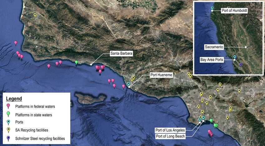
OCS Study
                                                  BOEM 2023-010

California Floating Offshore Wind
Regional Ports Assessment

January 2023

Authors:
Matt Trowbridge | MTrowbridge@moffattnichol.com
Jennifer Lim | JLim@moffattnichol.com
Shane Phillips | SPhillips@moffattnichol.com
Ashley Knipe | AKnipe@moffattnichol.com

Prepared under Contract No.140M0121D0008
By
Moffatt & Nichol
1300 Clay Street, Suite 350
Oakland, CA 94612
+1 510 788 8959

U.S. Department of the Interior
Bureau of Ocean Energy Management
Pacific OCS Region, Camarillo, CA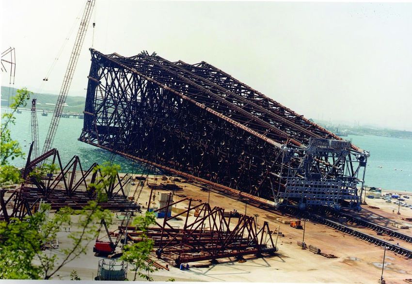
DISCLAIMER
Study concept, oversight, and funding were provided by the U.S. Department of the Interior, Bureau of
Ocean Energy Management (BOEM), Pacific OCS Region, Camarillo, CA under Contract Number
140M0121D0008. This report has been technically reviewed by BOEM, and it has been approved for
publication. The views and conclusions contained in this document are those of the authors and should
not be interpreted as representing the opinions or policies of BOEM, nor does mention of trade names or
commercial products constitute endorsement or recommendation for use.

                                  REPORT AVAILABILITY
To download a PDF file of this report, go to the U.S. Department of the Interior, Bureau of Ocean
Energy Management Recently Completed Environmental & Technical Studies – Pacific webpage
(https://www.boem.gov/Pacific-Completed-Studies/), and click on the link for 2023-010.

                                             CITATION
Trowbridge M, Lim J, Phillips S (Moffatt & Nichol, Long Beach, CA). 2023. California Floating
       Offshore Wind Regional Ports Assessment. U.S. Department of the Interior, Bureau of Ocean
       Energy Management. 61 p. Report No.: OCS Study BOEM 2023-010. Contract No.:
       140M0121D0008.

                                     ABOUT THE COVER
Photo Description: Floating offshore wind turbines installed at sea and one turbine being towed out for
installation.

Photo Credit: Moffatt & Nichol

                                   ACKNOWLEDGMENTS
We would like to thank the following for their time and participation in completing this effort: City of
Alameda, City of Morro Bay, Crescent City Harbor District, Diablo Canyon, Port of Benicia, Port of
Hueneme, Port of Humboldt, Port of Long Beach, Port of Los Angeles, Port of Oakland, Port of Redwood
City, Port of Richmond, Port of San Diego, Port San Luis, Port of San Francisco, Port of Stockton, Port of
San Francisco, AMPORTS (Port of Benicia), BAE Systems (Port of San Diego), NASSCO (Port of San
Diego), and Pasha Automotive Services (Port of San Diego).
Contents
List of Figures ............................................................................................................................................. ii
List of Tables ............................................................................................................................................... ii
List of Abbreviations and Acronyms ....................................................................................................... iv
How to Read this Report ............................................................................................................................ 1
Executive Summary .................................................................................................................................... 3
1      Introduction ......................................................................................................................................... 6
2      Port Requirements .............................................................................................................................. 9
    2.1     Turbine Size .................................................................................................................................. 9
    2.2     Port Requirements ...................................................................................................................... 11
       2.2.1 Port Wharf and Loading Requirements ................................................................................... 11
       2.2.2 Floating Foundation Type and Launching ............................................................................... 11
       2.2.3 Wet Storage Requirements ..................................................................................................... 13
       2.2.4 Additional Port Requirements ................................................................................................. 13
    2.3     Design Life .................................................................................................................................. 13
    2.4     Governing Codes, Standards, and References .......................................................................... 13
3      Deployment Scenarios ..................................................................................................................... 16
    3.1     Deployment Targets and Planning Goals ................................................................................... 16
    3.2     Required Number of Port Sites ................................................................................................... 16
       3.2.1 Required Number of Staging and Integration Sites ................................................................ 17
       3.2.2 Required Number of Blade Manufacturing / Fabrication Sites ................................................ 18
       3.2.3 Required Number of Tower Manufacturing / Fabrication Sites ............................................... 18
       3.2.4 Required Number of Nacelle Assembly Sites ......................................................................... 19
       3.2.5 Required Number of Foundation Assembly Sites ................................................................... 20
4      Port Outreach .................................................................................................................................... 21
5      Port Inventory and Assessment ...................................................................................................... 22
    5.1     Staging and Integration (S&I) Sites ............................................................................................. 22
    5.2     Manufacturing / Fabrication (MF) Sites ....................................................................................... 24
    5.3     Operations and Maintenance (O&M) Sites ................................................................................. 25
    5.4     Summary ..................................................................................................................................... 27
6      Offshore Oil and Gas Decommissioning Considerations............................................................. 31
    6.1     California Offshore Oil and Gas Platforms Background.............................................................. 32
    6.2     Planning Process for Decommissioning Offshore Oil and Gas Platforms on the Pacific Federal
            OCS ............................................................................................................................................ 36
    6.3     Case Study – Decommissioning of Brent Field Platforms Alpha and Delta................................ 37
       6.3.1 Topside Removal .................................................................................................................... 39
       6.3.2 Steel Jacket Removal ............................................................................................................. 43
    6.4     California Port Needs .................................................................................................................. 44
    6.5     Port Assessment ......................................................................................................................... 47
    6.6     Recommendations / Synergies Between OSW and Offshore Oil and Gas Decommissioning ... 50
    6.7     Industrial Circular Economy: Energy Transition Facility – Ardersier Port, U.K. .......................... 51
7      Conclusion and Next Steps ............................................................................................................. 53
8      References ......................................................................................................................................... 55
List of Relevant Literature ........................................................................................................................ 58
  Offshore Wind Literature ......................................................................................................................... 58

                                                                                i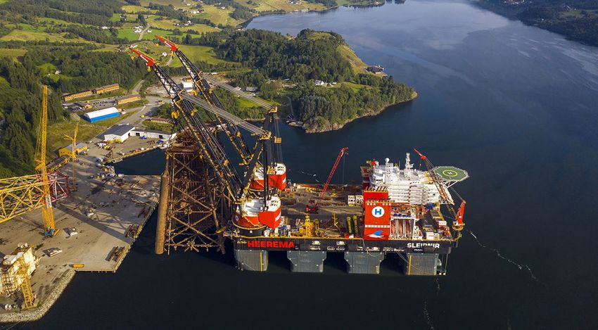
Offshore Oil and Gas Decommissioning Literature................................................................................. 59

List of Figures
Figure 1. California final lease areas (BOEM 2022) ..................................................................................... 8
Figure 2. Floating offshore wind turbine dimensions (20 – 25 MW) ........................................................... 10
Figure 3. Illustration of floating foundation types (left to right: spar, semi-submersible, TLP) (NREL
               2022) ...................................................................................................................................... 12
Figure 4. Staging and integration (S&I) candidate status of each port ....................................................... 23
Figure 5. Manufacturing / fabrication (MF) candidate status of each port .................................................. 25
Figure 6. Operation and maintenance (O&M) candidate status of each port ............................................. 27
Figure 7. S&I, MF, and O&M candidate status for each port ...................................................................... 28
Figure 8. Platform Harmony jacket onshore prior to installation (Bull 2018) .............................................. 31
Figure 9. California offshore oil & gas platforms (CSLC 2018) ................................................................... 34
Figure 10. Schematic of typical offshore oil & gas platform (Bernstein 2017) ............................................ 35
Figure 11. Schematic of skirt piles (Frieze, year unknown) ........................................................................ 36
Figure 12. Photo of Brent Alpha prior to decommissioning in the North Sea (Shell 2020a) ....................... 38
Figure 13. Photo of Brent Delta prior to decommissioning in the North Sea (Adams 2015) ...................... 39
Figure 14. Pioneering Spirit transporting the Brent Delta topside (Shell 2019) .......................................... 40
Figure 15. Iron Lady barge transporting the Brent Delta topside (Shell 2017b) ......................................... 40
Figure 16. Skidding the Brent Delta topside from Iron Lady to Quay 6 at the Able Seaton Port
             Facility, U.K. (Shell 2019) ....................................................................................................... 41
Figure 17. Skidding Brent Delta topside onto Able Seaton Port (Shell 2019) ............................................ 42
Figure 18. Skidding Brent Delta topside onto Able Seaton Port (Shell 2019) ............................................ 42
Figure 19. Sleipnir transporting upper Brent Alpha’s upper jacket (Heerema Marine Contractors) ........... 43
Figure 20. Sleipnir loading Brent Alpha’s upper jacket onto the wharf at AFOD Facility in Norway
             (Heerema Marine Contractors) .............................................................................................. 44
Figure 21. Locations of offshore oil & gas platforms, ports, and metal recycling facilities ......................... 48
Figure 22. Ardersier Port site plan (Industrial Circular Economy 2021) ..................................................... 51
Figure 23. Ardersier Port fully circular energy transition facility (Industrial Circular Economy 2021) ......... 52

List of Tables
Table 1. Floating offshore wind turbine dimensions (20 – 25 MW)............................................................. 10
Table 2. Port infrastructure requirements ................................................................................................... 11
Table 3. Deployment targets ....................................................................................................................... 16
Table 4. Required number of sites to meet 2045 deployment targets ........................................................ 17
Table 5. Required number of S&I sites to meet deployment scenario targets ........................................... 17
Table 6. Assumed turbine production rate per week .................................................................................. 18

                                                                              ii
Table 7. Required number of blade MF sites to meet deployment targets ................................................. 18
Table 8. Required number of tower MF sites to meet deployment targets ................................................. 19
Table 9. Required number of nacelle assembly sites to meet deployment targets .................................... 19
Table 10. Required number of foundation assembly sites to meet deployment targets ............................. 20
Table 11. Summary of potential California offshore wind port sites ........................................................... 29
Table 12. Data for platforms in state waters ............................................................................................... 32
Table 13. Data for platforms in federal waters ............................................................................................ 32
Table 14. Comparison of platforms Brent Alpha, Brent Delta, and Harmony ............................................. 38
Table 15. Design vessel characteristics ...................................................................................................... 40
Table 16. Vessel characteristics ................................................................................................................. 43
Table 17. Port infrastructure requirements for offshore oil & gas platform decommissioning .................... 46
Table 18. Port assessment for offshore oil & gas decommissioning .......................................................... 49
Table 19. Comparison of offshore wind and offshore oil & gas decommissioning key criteria ................... 51

                                                                         iii
List of Abbreviations and Acronyms
AB        Assembly Bill
ABS       American Bureau of Shipping
ACI       American Concrete Institute
AFOD      AF Offshore Decommissioning
AISC      American Institute for Steel Construction
API       American Petroleum Institute
ASCE      American Society of Civil Engineers
AWS       American Welding Society
BOEM      Bureau of Ocean Energy Management
BSEE      Bureau of Safety and Environmental Enforcement
CARB      California Air Resources Board
CBC       California Building Code
CEC       California Energy Commission
CEQA      California Environmental Quality Act
cfs       cubic feet per second
CSLC      California State Lands Commission
CTV       Crew transfer vessel
e.g.      Exempli gratia (for example)
EIR       Environmental Impact Report
EIS       Environmental Impact Statement
etc.      et cetera
ft        feet
GBS       Gravity-based structure
GW        Gigawatts
i.e.      id est (that is)
IDIQ      Indefinite Delivery Indefinite Quantity
IDWG      Interagency Decommissioning Working Group
LSU       Louisiana State University
m         meter / meters
M&N       Moffatt & Nichol
MF        Manufacturing / Fabrication
MMS       Minerals Management Service
MW        Megawatt
N/A       Not applicable
NEPA      National Environmental Policy Act
NFPA      National Fire Protection Association
NOA       Notice of Availability
NOI       Notice of Intent
NOP       Notice of Preparation
NREL      National Renewable Energy Laboratory

                                                    iv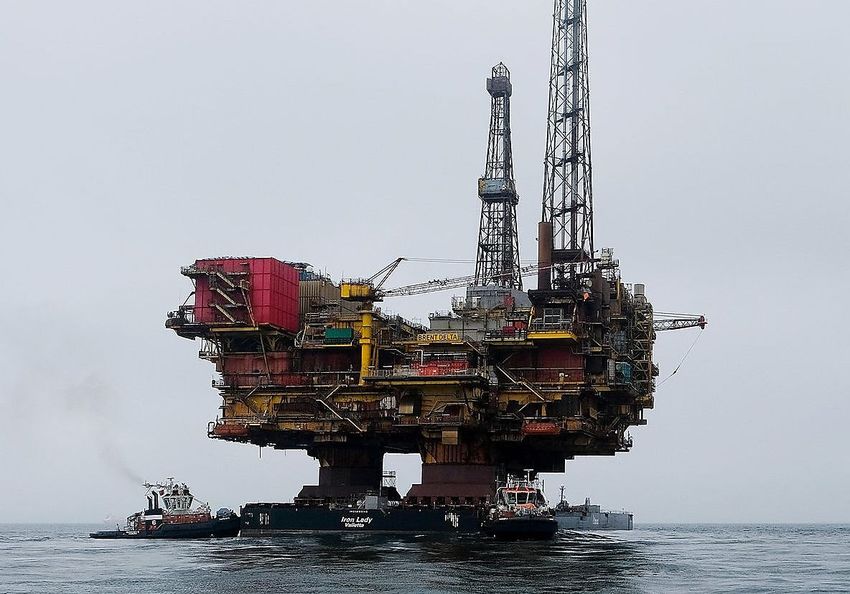
O&M           Operation and Maintenance
OCIMF         Oil Companies International Marine Forum
OCS           Outer Continental Shelf
OEM           Original equipment manufacturers
OSW           Offshore wind
Pacific OCS   Outer Continental Shelf off the coasts of California, Oregon, Washington, and Hawaii
PARS          port access route study
PIANC         Permanent International Association of Navigation Congresses
PPE           Personal protection equipment
psf           pounds per square foot
ROD           Record of Decision
RORO          Roll-on / roll-off
S&I           Staging and Integration
SATV          Service accommodation transfer vessel
Schatz        Schatz Energy Research Center
SLO           San Luis Obispo
SOV           Service operations vessel
SPMTs         self-propelled modular trailers
TLP           Tension Leg Platform
U.K.          United Kingdom
UC            University of California
UFC           Unified Facilities Criteria
U.S.          United States
USACE         United States Army Corps of Engineers
USC           University of Southern California
USCG          U.S. Coast Guard
USDOE         U.S. Department of Energy
WEA           Wind Energy Area
WTG           Wind turbine generator
yr            Year

                                                      v
How to Read this Report
The overall goals of this California Floating Offshore Wind Energy Regional Ports Assessment are to:

    1. Identify port requirements and deployment scenarios needed to support an offshore wind industry
       in California, concurrently with reasonably foreseeable Pacific Outer Continental Shelf (OCS) oil
       and gas decommissioning activities; and,
    2. Assess physical, operational, and regulatory capabilities and constraints of port facilities and
       infrastructure.

This report has the following structure:

    •   Section 1 provides an introduction and background to the study.
    •   Section 2 documents the port requirements from a previous Bureau of Ocean Energy
        Management (BOEM) study titled Port of Coos Bay Port Infrastructure Assessment for Offshore
        Wind Development (Moffatt & Nichol 2022).
    •   Section 3 identifies the five deployment scenarios for 2030 through 2050 and determines the
        number of required staging and integration (S&I) and manufacturing/fabrication (MF) sites
        needed to meet the above deployment scenarios.
    •   Section 4 discusses the port outreach that was conducted as part of this study.
    •   Section 5 identifies the number and type of California port sites that are potentially available for
        offshore wind development.
    •   Section 6 identifies the port requirements for offshore oil and gas platform decommissioning and
        assesses which ports are ideal for this type of activity.
    •   Section 7 provides a summary of the study and recommended next steps.

There are three (3) main port facilities that are required for offshore wind development: staging and
integration (S&I), manufacturing/fabrication (MF), and operations and maintenance (O&M) facilities.
The following describes the type of activities conducted at each. For details on the specific requirements
of each site, refer to Section 2.

    •   Staging and Integration (S&I) Site: a site to receive, stage, and store offshore wind components
        and to assemble the floating turbine system for towing to the offshore wind area. This facility is
        likely to support the following services:
            o Turbine Maintenance Site: a facility to perform major maintenance on a fully
                 assembled turbine system that cannot otherwise be performed in the offshore wind area,
                 such as replacement of a nacelle or blade.
    •   Manufacturing / Fabrication (MF) Site: a port site located on a navigable waterway that
        receives raw materials via road, rail, or waterborne transport and creates larger components in the
        offshore wind supply chain. This site typically includes factory and/or warehouse buildings and
        space for storage of completed components.
    •   Operations and Maintenance (O&M) Site: a base of wind farm operations with warehouses/
        offices, spare part storage, and marine facility to support vessel provisioning and refueling/
        charging for the following O&M vessels during the operational period of the offshore wind farm:
            o Crew Transfer Vessel (CTV): transfers small crews to offshore wind turbine
                 installations for day-trip O&M visits and inspections.
            o Service Operating Vessel (SOV): vessels that loiter and operate as in-field
                 accommodations for workers and platform assist for wind turbine servicing and repair
                 work. This vessel may remain in the vicinity of an offshore windfarm for an extended
                 period of time with a permanent or semi-permanent personnel rotation.

                                                     1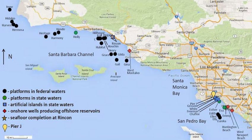
o   Service Accommodation Transfer Vessel (SATV): intermediate between SOVs and
                CTVs, with ability to sleep onboard for multiday trips.

Additional offshore wind port sites that are not included in this study but will be required for offshore
wind industry use include:

    •   Other Types of Offshore Wind Port Sites:
           o Installation Support Site: a base of construction operations for the fleet of construction
               vessels necessary for construction and commissioning of the offshore wind farm.
           o Mooring Line, Anchor, and Electrical Cable Laydown Site: a site to receive and stage
               mooring lines, anchors, and electrical cables to support the installation of the offshore
               wind farm.
           o Cable Landing Site: locations for the electrical cables to transition from the offshore
               (e.g., subsea cables) to a grid connection location. These sites may include electrical
               infrastructure onshore.
           o End of Life Decommissioning Site: a site to decommission, disassemble, recycle, and
               dispose of turbine systems that are at end of life.

                                                      2
Executive Summary
The Bureau of Ocean Energy Management (BOEM) is interested in a study of California ports to support
offshore wind development. Specifically, the infrastructure apart from the offshore energy facility itself,
such as ports, navigation, transmission, and supply chain. This study will address the needs and
requirements of California ports to support floating offshore wind. It will also support the California
Assembly Bill (AB) 525 Strategic Plan that is due June 30, 2023 (Chiu 2021).
The objective of this study is to develop offshore wind deployment scenarios, which include size
(gigawatts [GW]) and timing (e.g., years 2030 and 2045), as well as a high-level screening study to
identify the required quantity and size of various port facilities needed to support the deployment
scenarios. The feasibility of port upgrades and associated cost estimates are not included in this study but
will be included in the following BOEM study titled California Floating Offshore Wind Regional Ports
Feasibility Analysis. In addition to an assessment of existing ports, this study also considered port
capabilities and requirements needed to accommodate current and anticipated Pacific Outer Continental
Shelf (OCS) oil and gas decommissioning activities.
Based on this study, multiple port sites will need to be developed to meet the identified offshore wind
deployment targets. Fortunately, many existing port sites within California were identified that could
meet these goals. To do so, this will require significant investment into existing ports to support the
offshore wind industry needs.
In a letter to the California Air Resources Board (CARB) dated July 22, 2022, Governor Gavin Newsom
urged the California Energy Commission (CEC) to establish an offshore wind planning goal of at least
20 GW by 2045 (Newsom 2022). On August 1, 2022, the CEC established a preliminary offshore wind
planning goal of 2 to 5 GW by 2030 and 25 GW by 2045 for California (Flint et al. 2022). Using these
goals as a baseline, this study assessed a range of deployment scenarios for 2030 through 2050, which can
be found in Section 3.
From these deployment targets, the required number of staging and integration (S&I) and manufacturing /
fabrication (MF) sites were determined in Section 3. The determination of the number of operations and
maintenance (O&M) sites is not included in this study but will be provided in the future AB 525 Strategic
Plan. Refer to Table 2 and Section 2 for the requirements of each type of port site (e.g. acreage size,
length of wharf, berth depth, etc.).
After the deployment targets and number of required port sites were identified, an inventory of potentially
available port sites within California was taken. Moffatt & Nichol (M&N), BOEM, and California State
Lands Commission (CSLC) conducted outreach meetings with seventeen (17) California ports/facilities
and four (4) additional port tenants/operators to determine interest for offshore wind development and
assess availability and suitability of potential sites without relocating existing uses (e.g., container, cargo,
fishing, recreational boating, etc.). For a detailed list of the California ports and port tenants/operators that
were contacted as part of this outreach, refer to Section 5.
Following outreach efforts with the California ports, an assessment of the ports was conducted in Section
6. It is important to note that currently, existing port sites on the United States (U.S.) West Coast are not
ready to serve the offshore wind industry from a port infrastructure perspective (i.e., wharf, navigation
channel, backlands, etc.). All potential port sites will require some level of investment to upgrade existing
facilities, such as construction of a new wharf to withstand heavier loading and dredging of the navigation
channel and/or berth pockets.
S&I sites require a large amount of space, deep navigation channels, and cannot have any air draft
restrictions since the fully assembled turbine systems, which are 1,100 feet above water, need to be towed
3out to the installation site at the wind energy area (WEA). Therefore, only the ports of Humboldt, Los
Angeles, and Long Beach were identified to have good S&I candidate sites that meet the required
criteria.
MF sites can occupy less space than S&I sites and be at locations with air draft restrictions since the
components (e.g., tower sections, nacelles, blades, and floating foundations) can be transported
horizontally via vessel or barge. Therefore, ports located behind bridges, such as those in the Bay Area,
are candidates for offshore wind development as MF sites. The following ports, ordered north to south,
were identified to have good MF candidate sites with adequate acreage:
• Port of Humboldt
• Port of Benicia
• Port of Stockton
• Port of Richmond
• Port of San Francisco
• Port of Redwood City
• Port of Los Angeles
• Port of Long Beach
• Port of San Diego 1
Ideally, O&M sites that transfer crew to and from the offshore wind farm shall be close to the wind farm
location to minimize travel time. The following ports, ordered north to south, were identified to have
good O&M candidate sites:
• Crescent City Harbor District
• Port of Humboldt
• City of Morro Bay
• Diablo Canyon Power Plant
• Port San Luis
• Port of Hueneme
While this study focuses on assessing the seventeen (17) existing California ports/facilities, another study
for the CSLC assessed additional existing harbors between San Francisco and Long Beach to identify
additional O&M sites that are closer to the Morro Bay WEA (Moffatt & Nichol 2023b).
The information gathered from this, and previous studies, will inform the next BOEM study titled
California Floating Offshore Wind Regional Ports Feasibility Analysis, which will assess the feasibility
of port upgrades and associated cost estimates and construction timelines. In addition, the AB 525
Strategic Plan, with support from the BOEM and CSLC studies, will include the following:
• Identify required port infrastructure improvements, including cost and schedule,
• Identify impacts to natural and cultural resources, including coastal resources, fisheries, and
Native American and Indigenous peoples,
• Rank the recommended port sites,
• Determine workforce development needs, training, and strategy,
• Develop the seaport chapter for the AB 525 Strategic Plan due June 30, 2023.
1
Within the Port of San Diego, manufacturing / fabrication of offshore wind floating foundations is possible at the
NASSCO site and steel component fabrication and ship repair services are possible at the BAE Systems site.
4As part of this study of assessing California ports, BOEM has also indicated the need to identify port
requirements and capabilities to support Pacific OCS oil and gas decommissioning activities. As the
twenty-three (23) Federal oil and gas platforms offshore southern California reach the end of their
production lifetimes, decommissioning is the next step. As of this writing, eight Federal offshore oil and
gas platforms have already ceased production, therefore requiring the platforms to undergo the
decommissioning process. Identifying port requirements and capabilities to support the current and
increasing Pacific OCS oil and gas decommissioning activities is an important outcome of this study.
After identifying the necessary port requirements for decommissioning activities, an assessment was
completed to determine whether these activities could be co-located with offshore wind port sites. Refer
to Section 7 for offshore oil and gas decommissioning considerations.
There are some synergies between the offshore wind industry and the offshore oil and gas
decommissioning industry. These synergies include similar business lines from a terminal equipment,
operator, and vessel perspective, and the efficiency of two facilities located within the same port.
However, they cannot be located at the same port site as both need designated berth and upland space for
long periods of time. Of the ports in California, the Port of Los Angeles and Port of Long Beach were
identified to be the ideal locations for offshore oil and gas platform decommissioning due to
proximity to the offshore oil and gas platforms, access to steel recycling facilities, potential for large
purpose-built sites, no air draft restrictions, wide entrance channels, and large navigation channels.
51 Introduction
The United States (U.S.) Department of the Interior, Bureau of Ocean Energy Management (BOEM), as
mandated by the Outer Continental Shelf (OCS) Lands Act, administers exploration and development of
energy and mineral resources in federal waters. This includes the responsibility of issuing a lease,
easement, or right‐of‐way for offshore energy and mineral resources in federal waters off the coasts of
California, Oregon, Washington, and Hawaii – the Pacific OCS Region.
The Pacific OCS is characterized by rapidly increasing water depths that exceed the feasible limits of
traditional fixed-bottom offshore wind turbines. Thus, floating offshore wind technology is more suitable
for this region. To construct floating offshore wind turbines, the turbine components will need to be
fabricated, assembled, and transported from an onshore port to the offshore wind site. Existing port
infrastructure on the U.S. West Coast, including the California coast, is not adequate to support these
activities and significant port investment is required to develop offshore wind port facilities.
BOEM is interested in a study of California ports to support offshore wind development. Specifically, the
infrastructure apart from the offshore energy facility itself, such as ports, navigation, transmission, and
supply chain. This study will address the needs and requirements of California ports to support floating
offshore wind. It will also support the California Assembly Bill (AB) 525 Strategic Plan that is due June
30, 2023 (Chiu 2021).
It should be noted that this study is part of an overarching BOEM Indefinite Delivery Indefinite Quantity
(IDIQ) contract that includes the following three studies:
• Task Order 1: Port of Coos Bay Port Infrastructure Assessment for Offshore Wind Development
study, published in 2022.
• Task Order 2: California Floating Offshore Wind Regional Ports Assessment study, to be
published in 2023 (this report).
• Task Order 3: California Floating Offshore Wind Regional Ports Feasibility Analysis study, to be
published in 2023 (next report).
Regarding port infrastructure, the AB 525 Strategic Plan shall identify available port space and the
necessary investments to improve waterfront facilities for the floating offshore wind industry. In addition,
the AB 525 Strategic Plan shall include identification of sea space for wind energy areas (WEAs) to
accommodate the offshore wind planning goals for 2030 and 2045 (Chiu 2021). To date, BOEM has
identified two offshore WEAs off the state of California, the Humboldt WEA and Morro Bay WEA.
The objective of this study is to develop offshore wind deployment scenarios, which include size
(gigawatts [GW]) and timing (e.g., years 2030 and 2045), as well as a high-level screening study to
identify the required quantity and size of various port facilities needed to support the deployment
scenarios. The feasibility of port upgrades and associated cost estimates are not included in this study, but
will be included in the following BOEM study titled California Floating Offshore Wind Regional Ports
Feasibility Analysis. In addition to an assessment of existing ports, this study also considered port
capabilities and requirements needed to accommodate current and anticipated OCS oil and gas
decommissioning activities.
The overall goals of the California Floating Offshore Wind Regional Ports Assessment are to:
1. Identify port requirements and deployment scenarios needed to support an offshore wind industry
in California, concurrently with reasonably foreseeable OCS oil and gas decommissioning
activities; and,
62. Assess physical, operational, and regulatory capabilities and constraints of port facilities and
infrastructure.
The key to a successful port development strategy requires coupling it with the proposed California
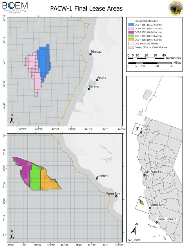
offshore wind solicitation schedule and deployment scenarios. On December 6, 2022, BOEM held an
offshore wind energy lease sale for five lease areas, two within the Humboldt WEA and three within the
Morro Bay WEA (BOEM 2022). The size of each lease area ranges from 63,338 to 80,418 acres and has a
potential installation capacity of 769 to 976 megawatts (MW), refer to Figure 1. On December 7, 2022,
the lease sale ended and five provisional winners were announced – RWE Offshore Wind Holdings, LLC;
California North Floating LLC; Equinor Wind US LLC; Central California Offshore Wind LLC; and
Invenergy California Offshore LLC. It is imperative that the build out of port infrastructure can support
this proposed schedule and offshore wind deployment scenarios. This study examines the following port
development options:
• Utilize a single port (or as few as possible) to support all floating offshore wind fabrication,
assembly, and operations (e.g., co-locate integration, fabrication, and operations and maintenance
facilities).
• Utilize multiple port facilities to optimize development at the most ideal locations and to spread
the economic impact throughout the state (e.g., separate integration, fabrication, and operations
and maintenance facilities).
This study, and additional offshore wind studies, will help inform the AB 525 Strategic Plan that is
intended to present findings that will help the state make decisions regarding the offshore wind industry
within California. The AB 525 Strategic Plan will be informed by the following studies:
• BOEM Study (Task Order 1), Port of Coos Bay Port Infrastructure Assessment for Offshore
Wind Development (Moffatt & Nichol 2022)
o Extensive offshore wind developer outreach was conducted within this Port of Coos Bay,
Oregon study to help inform the port facility requirements for offshore wind development
on the U.S. West Coast. These port requirements are summarized within Section 2.
• BOEM Study (Task Order 2), California Floating Offshore Wind Regional Ports Assessment (this
report)
o Extensive California port outreach was conducted for the entire state within this study to
assess how much space/acreage the existing California ports have available to support the
offshore wind industry.
• BOEM Study (Task Order 3), California Floating Offshore Wind Regional Ports Feasibility
Analysis (Moffatt & Nichol 2023a) (next BOEM study)
o The feasibility of port upgrades and associated cost estimates and timelines will be
determined and assessed for the sites previously identified in BOEM Task Order 2.
• California State Lands Commission (CSLC) Study, Alternative Port Assessment to Support
Offshore Wind (Moffatt & Nichol 2023b)
o A feasibility assessment was conducted for the region between San Francisco and Long
Beach to determine the opportunities and limitations for creating new alternative port
locations to support the offshore wind industry.
7Figure 1. California final lease areas (BOEM 2022)
82 Port Requirements
The floating offshore wind industry requires port sites to stage, assemble, and provide ongoing operations
and maintenance of the wind turbines. Based on the industry outreach completed for the BOEM study
titled Port of Coos Bay Port Infrastructure Assessment for Offshore Wind Development, this section
defines the requirements of this port assessment and the design criteria for the following types of offshore
wind port sites (Moffatt & Nichol 2022):
• Staging and Integration (S&I) Site: a site to receive, stage, and store offshore wind components
and to assemble the floating turbine system for towing to the offshore wind area. This facility is
likely to support the following services:
o Turbine Maintenance Site: a facility to perform major maintenance on a fully
assembled turbine system that cannot otherwise be performed in the offshore wind area
such as replacement of a nacelle or blade.
• Manufacturing/Fabrication (MF) Site: a port site located on a navigable waterway that receives
raw materials via road, rail, or waterborne transport and creates larger components in the offshore
wind supply chain. This site typically includes factory and/or warehouse buildings and space for
storage of completed components.
• Operation and Maintenance (O&M) Site: a base of wind farm operations with warehouses/
offices, spare part storage, and marine facility to support vessel provisioning and refueling/
charging for the following O&M vessels during the operational period of the offshore wind farm:
o Crew Transfer Vessel (CTV): transfers small crews to offshore wind turbine
installations for day-trip O&M visits and inspections.
o Service Operating Vessel (SOV): vessels that loiter and operate as in-field
accommodations for workers and platform assist for wind turbine servicing and repair
work. This vessel may remain in the vicinity of an offshore windfarm for an extended
period of time with a permanent or semi-permanent personnel rotation.
o Service Accommodation Transfer Vessel (SATV): intermediate between SOVs and
CTVs, with ability to sleep onboard for multiday trips.
Additional offshore wind port sites that are not included in this study but will be required for offshore
wind industry use include:
• Other Types of Offshore Wind Port Sites:
o Installation Support Site: a base of construction operations for the fleet of construction
vessels necessary for construction and commissioning of the offshore wind farm.
o Mooring Line, Anchor, and Electrical Cable Laydown Site: a site to receive and stage
mooring lines, anchors, and electrical cables to support the installation of the offshore
wind farm.
o Cable Landing Site: locations for the electrical cables to transition from the offshore
(e.g., subsea cables) to a grid connection location. These sites may include electrical
infrastructure onshore.
o End of Life Decommissioning Site: a site to decommission, disassemble, recycle, and
dispose of turbine systems that are at end of life.
2.1 Turbine Size
Based on the information obtained from a previous BOEM study and industry outreach, currently 12-MW
offshore wind turbine systems are commercially available; however, the anticipated size of turbine
9systems to be installed on the U.S. West Coast may be 15 MW or larger (Moffatt & Nichol 2022). Table
1 summarizes the anticipated dimensions for a floating turbine system with capacity of up to 20 – 25
MW. Turbine device dimensions provided are relative to the future industry needs for 15 to 25-MW size
devices. Smaller size devices (beam, draft) are currently in development but are at reduced turbine
capacity. The values outlined in the table are those recommended for planning a major port terminal on a
50-year time horizon to meet the anticipated needs of the continuously developing offshore wind industry.
In addition, Figure 2 shows a depiction of the turbine dimensions.
Table 1. Floating offshore wind turbine dimensions (20 – 25 MW)
Approximate Approximate
Floating Offshore Wind Turbine
Dimension [ft] Dimension [m]
Foundation Beam / Width Up to 425 ft x 425 ft Up to 130 m x 130 m
Draft (Before Integration) 15 – 25 ft 4.5 – 7.5 m
Draft (After integration) 20 – 50 ft 6 – 15 m
Hub/Nacelle Height (from Water Level) Up to 600 ft Up to 183 m
Tip Height (from Water Level) Up to 1,100 ft Up to 335 m
Rotor Diameter Up to 1,000 ft Up to 305 m
Figure 2. Floating offshore wind turbine dimensions (20 – 25 MW)
102.2 Port Requirements
The following parameters document the required port infrastructure to unload, store, pre-commission, and
pre-assemble floating offshore wind farm components per the BOEM Port of Coos Bay study (Moffatt &
Nichol 2022).
2.2.1 Port Wharf and Loading Requirements
Per discussions with industry, the S&I wharf shall accommodate the delivery of components and at least
two turbine assemblies moored adjacent to one another, resulting in approximately 1,500 feet of quayside
space, as summarized in Table 2. For O&M and component manufacturing facilities, the length of the
wharf is dependent on the vessel type it serves. For example, SOV and CTV for O&M facilities and
delivery vessels and delivery barges for component manufacturing facilities.
In general, the wharf and uplands area for component manufacturing sites shall have a capacity of 2,000 –
3,000 pounds per square foot (psf) to support offshore wind turbine generator (WTG) components. At
S&I sites, the wharf loading will be higher where the crane for turbine assembly is located. Existing
crawler cranes, such as the Liebherr 1300, are not large enough to assemble turbines greater than 15 MW.
Thus, ring cranes or larger crawler or mobile cranes will likely be required to integrate components,
requiring a loading capacity of 6,000 psf on the wharf. Loading at O&M facilities is expected to range
from 100 – 500 psf.
The size of a site is also dependent on the type of facility it is. For an O&M facility, the site shall be
approximately 5 – 10 acres. For component manufacturing and staging and integration sites, a range of
30 – 100 acres is requested depending on the developer and their use.
Table 2. Port infrastructure requirements
Approximate Approximate Approximate
Floating Offshore Wind Turbine Criteria for S&I Criteria for MF Criteria for O&M
Sites Sites Sites
Acreage, minimum 30 – 100 acres 30 – 100 acres 5 – 10 acres
Wharf Length 1,500 ft 800 ft 300 ft
Minimum Draft at Berth 38 ft 38 ft 20 – 30 ft
Draft at Sinking Basin* 40 – 100 ft N/A N/A
Wharf Loading > 6,000 psf Up to 6,000 psf 100 – 500 psf
> 2,000 – 3,000 > 2,000 – 3,000
Uplands / Yard Loading (for WTG components) N/A
psf psf
*Options for transfer of floating foundation from land to water include use of semi-submersible barge and sinking basin, ramp
system, or direct transfer methods (lifting portions or complete foundation units from land into water)
2.2.2 Floating Foundation Type and Launching
Currently, there are three types of floating foundations for floating offshore wind turbines, as shown in
Figure 3:
• Spar: A Spar floating foundation, constructed of either concrete, steel, or a hybrid combination,
is a cylinder that floats vertically in the water.
11• Tension Leg Platform (TLP): A TLP floating foundation, constructed of steel, is comprised of
multiple columns and pontoons. It’s mooring system requires vertical tensioned tendons, which
provide stability to the structure.
• Semi-submersible: A semi-submersible floating foundation, constructed of either concrete, steel,
or a hybrid combination, is comprised of a submerged hull with multiple pontoons and columns.
Figure 3. Illustration of floating foundation types (left to right: spar, semi-submersible, TLP) (NREL
2022)
Although a semi-submersible floating foundation requires increased port infrastructure capacity, it is the
most probable technology to be used on the U.S. West Coast as Spar foundations are not feasible on the
West Coast, due to required deep draft, and offshore wind developers have indicated that semi-
submersible foundations are preferred. Therefore, by assuming semi-submersible foundations will be
utilized for offshore wind development on the West Coast, the port requirements developed in Table 2
are also suitable for TLP foundations – if utilized – as they are smaller and require less port infrastructure
capacity.
A major challenge the industry identified is the transfer of the completed floating foundation from the
assembly wharf into the water (i.e., launching). Several options are available to overcome this challenge
and each developer may prefer a different option; however, a few common approaches were identified:
• Semi-Submersible Barge: The floating foundation is moved from the wharf onto the barge and
the barge is moved to a 40 – 100-foot-deep sinking basin where the barge is partially submerged
by taking on ballast and the foundation is floated off the barge.
12• Ramp System: The floating foundation is moved onto a rail system and travels down a sloped
ramp into the water. This methodology is similar to a marine railway ship launching system.
• Direct Transfer: Methods that include lifting the floating foundation directly from the wharf into
the water (includes methods that involve placing pieces of the foundation into the water and
finalizing the construction in the water).
2.2.3 Wet Storage Requirements
Wet storage space is also required in addition to the water frontage and upland acreage. Ports must have
locations where floating foundation or integrated turbines can be safely moored to mitigate the risk of
weather downtime, vessel traffic, entrance channel congestion, and other transportation risks. This also
allows the developers to store and test the completed units and floating foundations to ensure they can
deliver the lease area on schedule. The size of the wet storage area is dependent on the developer’s
strategy, deployment schedule, and downtime risk.
2.2.4 Additional Port Requirements
Several additional port requirements include the following:
• Roll-on/Roll-Off (RORO) Capabilities: port sites shall have RORO capability built into the
wharf and yard to allow for a range of fabrication and assembly needs. Of particular importance
would be to allow for inside port transfers between multiple facilities. This may require the
construction of a sinking basin deeper than the proposed navigation channel depth.
• Green Port: new port terminals shall have infrastructure and equipment to support state and
federal carbon reduction initiatives, including electrification of the terminal operations and the
ability to accommodate vessel shore power. Considering greenhouse gas emission reduction
initiatives and desire to develop green ports, considerable load on the transmission grid may be
needed. An assessment of power grid upgrades for the proposed development site will be needed
to assess the range of power transmission upgrades needed to meet the vessel and terminal
operational needs.
• Shoreside Vessel Services: port sites will require all standard ship services (e.g., potable water),
shore power and security requirements.
• Buildings: indoor storage/warehouses are required for some items (e.g., floating foundation
mechanical equipment, painting, welding, etc.).
2.3 Design Life
All new marine structures at the port shall be designed for a 50-year service life. Design service life is
generally considered as the period of time during which a properly built and maintained structure is
expected to operate as designed without requiring major replacement or rehabilitation.
2.4 Governing Codes, Standards, and References
The following codes, standards, and references govern the design of port infrastructure and offshore wind
vessels.
American Bureau of Shipping (ABS):
• Guide for Building and Classing Floating Offshore Wind Turbine Installation, updated July 2014
13American Concrete Institute (ACI):
• ACI 318-19, Building Code Requirements for Structural Concrete
American Institute for Steel Construction (AISC):
• AISC 303-16, Code of Standard Practice for Steel Buildings and Bridges
• AISC 341-16, Seismic Provisions for Structural Steel Buildings
• AISC 360-16, Specification for Structural Steel Buildings
American Petroleum Institute (API):
• API RP 2A-LRFD, Recommended Practice for Planning, Designing and Constructing Fixed
Offshore Platforms – Load and Resistance Factor Design
American Society of Civil Engineers (ASCE):
• ASCE 7-16, Minimum Design Loads for Buildings and Other Structures
• ASCE 61-14, Seismic Design of Piers and Wharves
American Welding Society (AWS):
• AWS D1.1, Structural Welding Code, 2015
California Building Code (CBC):
• 2022 California Building Codes
National Fire Protection Association (NFPA):
• NFPA 307, Standard for the Construction and Fire Protection of Marine Terminals, Piers, and
Wharves
Oil Companies International Marine Forum (OCIMF):
• Mooring Equipment Guidelines (MEG4), 4th Edition, 2018
Permanent International Association of Navigation Congresses (PIANC):
• PIANC MarCom WG 145, Berthing Velocity Analysis of Seagoing Vessels over 30,000 dwt,
2022
• PIANC WG 121, Harbour Approach Channels – Design Guidelines, 2014
• PIANC WG 33, Guidelines for the Design of Fenders Systems, 2002
• PIANC WG 34, Seismic Design Guidelines for Port Structures, 2001
• PIANC WG 153, Recommendations for the Design & Assessment of Marine Oil &
Petrochemical Terminals, 2016
United States Army Corps of Engineers (USACE):
• USACE EM 1110-2-1100, Coastal Engineering Manual, 2002
• USACE EM 1110-2-1613, Hydraulic Design of Deep-Draft Navigation Projects, 2006
• USACE EM 1110-2-2502, Retaining and Flood Walls, 1989
14Unified Facilities Criteria (UFC):
• UFC 4-152-01 Design: Piers and Wharves, 2017
• UFC 4-159-03 Design: Moorings, 2020
153 Deployment Scenarios
On March 29, 2021, the Biden Administration established the goal of deploying 30 GW of offshore wind
power in the U.S. by 2030, which will largely be met using fixed-bottom wind turbines on the East Coast
and in the Gulf of Mexico (U.S. Government 2021). However, the water on the West Coast is
significantly deeper and will require floating wind turbines. Therefore, on September 15, 2022, the Biden
Administration announced the goal of deploying 15 GW of floating offshore wind power in the U.S. by
2035, building on the existing goal of 30 GW by 2030 (U.S. Government 2022).
In a letter to the California Air Resources Board (CARB) dated July 22, 2022, Governor Gavin Newsom
urged the California Energy Commission (CEC) to establish an offshore wind planning goal for the state
of California of at least 20 GW by 2045 (Newsom 2022). On August 1, 2022, the CEC established a
preliminary offshore wind planning goal of 2-5 GW by 2030 and 25 GW by 2045 (Flint 2022). Using
these goals as a baseline, this study assessed a range of deployment scenarios for 2030 through 2050,
specifically for the state of California. This section outlines the deployment scenarios and identifies the
number of port sites needed to achieve those goals.
3.1 Deployment Targets and Planning Goals
On June 6, 2022, BOEM, CSLC, and Moffatt & Nichol (M&N) held a Deployment Scenarios Workshop
to identify five deployment scenarios for 2030 through 2050. Using the CEC offshore wind planning
goals as the medium baseline, as discussed above, the additional deployment scenarios were established
using an incremental value of 0.5 GW per year. Table 3 summarizes these deployment targets.
Table 3. Deployment targets
Low Low-Medium Medium Medium-High High
Year
(0.5 GW/yr) (1 GW/yr) (1.5 GW/yr) (2 GW/yr) (2.5 GW/yr)
2030 1 GW 2 GW 3 GW 4 GW 5 GW
2035 3.5 GW 7 GW 10.5 GW 14 GW 17.5 GW
2038 5 GW 10 GW 15 GW 20 GW 25 GW
2045 8.5 GW 17 GW 25.5 GW 34 GW 42.5 GW
2048 10 GW 20 GW 30 GW 40 GW 50 GW
2050 11 GW 23 GW 33 GW 44 GW 55 GW
3.2 Required Number of Port Sites
From the various deployment targets, the required number of S&I and MF sites needed within California
to meet these targets can be determined. For this study, four different MF sites were considered:
• Blade MF Sites: a site that receives raw materials and manufactures blades
• Tower MF Sites: a site that receives raw materials and manufactures tower sections
• Nacelle Assembly Sites: a site that receives furnished parts of the nacelle and assembles the full
nacelle for turbine integration
• Foundation Assembly Sites: a site that receives furnished parts of the floating foundation and
assembles the full foundation system for turbine integration
16The determination of the number of O&M sites will be provided in the future AB 525 Strategic Plan.
Table 4 summarizes the number of S&I and MF sites required to meet the 2045 deployment targets
identified above.
Table 4. Required number of sites to meet 2045 deployment targets
Low Low-Medium Medium Medium-High High
Type of Site
(0.5 GW/yr) (1 GW/yr) (1.5 GW/yr) (2 GW/yr) (2.5 GW/yr)
S&I Sites 1 2 3 4 5
Blade MF Sites 1 2 2 3 3
Tower MF Sites 1 1 1 1 2
Nacelle Assembly Sites 1 1 1 1 1
Foundation Assembly Sites 1 2 2 3 4
Note: Number of port sites for each target and site type have been rounded up to the nearest whole number.
The following sections list the number of S&I and MF sites required to meet the deployment scenarios as
described in Table 3.
3.2.1 Required Number of Staging and Integration Sites
To meet the five deployment scenarios for 2030 through 2050, California would require the number of
S&I sites shown in Table 5. For Table 5 through Table 10, not applicable (N/A) is used to demonstrate
when it is not feasible to meet a target due to the assumed date when port sites are available for industry
use due to planning, permitting and regulatory approvals, engineering, and construction.
Table 5. Required number of S&I sites to meet deployment scenario targets
Low Low-Medium Medium Medium-High High
Year
(0.5 GW/yr) (1 GW/yr) (1.5 GW/yr) (2 GW/yr) (2.5 GW/yr)
2030 1 N/A N/A N/A N/A
2035 1 N/A N/A N/A N/A
2038 1 3 4 N/A N/A
2045 1 2 3 4 5
2048 1 2 3 4 5
2050 1 2 3 4 5
Note: Number of S&I sites for each target and year have been rounded up to the nearest whole number.
S&I Site Assumptions:
• Yard/Wharf Site Requirements: Sites in an existing California port are assumed to be upgraded
to provide at least 1,500 feet of heavy lift wharf with greater than 6,000 psf capacity and a
minimum of 75 acres of available land for developer use.
• Timing:
o Sites 1 and 2 are assumed to be located within the same port and ready for developer use
by 2028 and 2030, respectively.
o Sites 3 – 5 are assumed to be located within the same port complex and ready for
developer use by 2035.
• Turbine Size: Turbine sizes are assumed to be 15 MW up to 2035, then 20 MW after 2035.
• Production Rate: Assumed turbine system production rates per site are shown in Table 6.
17Table 6. Assumed turbine production rate per week
Year Site 1 Site 2 Site 3 Site 4 Site 5 Total
2028 – 2030 0.75 0 0 0 0 0.75
2030 – 2035 0.625 0.625 0 0 0 1.25
After 2035 0.625 0.625 1 1 1 4.25
3.2.2 Required Number of Blade Manufacturing / Fabrication Sites
To meet the five deployment scenarios for 2030 through 2050, California would require the number of
blade MF sites shown in Table 7. Note that this analysis assumes that blades required for projects before
2030 would need to be sourced outside of California. N/A is used to demonstrate when it is not feasible to
meet a target due to the assumed date when port sites are available for industry use due to planning,
permitting and regulatory approvals, engineering, and construction.
Table 7. Required number of blade MF sites to meet deployment targets
Low Low-Medium Medium Medium-High High
Year
(0.5 GW/yr) (1 GW/yr) (1.5 GW/yr) (2 GW/yr) (2.5 GW/yr)
2030 N/A N/A N/A N/A N/A
2035 1 2 N/A N/A N/A
2038 1 2 3 N/A N/A
2045 1 2 2 3 3
2048 1 1 2 3 3
2050 1 1 2 3 3
Note: Number of MF sites for each target and year have been rounded up to the nearest whole number.
Blade MF Site Assumptions:
• Yard/Wharf Site Requirements: Sites in an existing California port are assumed to be upgraded
to provide at least 600 feet of heavy lift wharf with greater than 6,000 psf capacity and a
minimum of 100 acres of available land for manufacturer use.
• Timing: Sites are assumed to be ready for use by 2030, 2032, and 2035.
• Production Rate: Blade MF sites are assumed to have a production rate of 182 blades per year.
Three blades are required for each turbine system.
• Turbine Size: Turbine sizes are assumed to be 15 MW up to 2035, then 20 MW after 2035.
3.2.3 Required Number of Tower Manufacturing / Fabrication Sites
To meet the five deployment scenarios for 2030 through 2050, California would require the number of
tower MF sites shown in Table 8. Note that this analysis assumes that tower sections required for projects
before 2030 would need to be sourced outside of California. N/A is used to demonstrate when it is not
feasible to meet a target due to the assumed date when port sites are available for industry use due to
planning, permitting and regulatory approvals, engineering, and construction.
18You can also read