Broadcast Positioning System (BPS) Using ATSC 3.0 - Tariq Mondal, Robert D. Weller, Sam Matheny - GPS
←
→
Page content transcription
If your browser does not render page correctly, please read the page content below

Broadcast Positioning System
 (BPS) Using ATSC 3.0

 Tariq Mondal, Robert D. Weller, Sam Matheny

What is BPS?
A system and method of estimating time and
 position at a receiver using Next Gen TV
 broadcast signals

 Compliant with Next Gen TV (ATSC 3.0)
 standard currently being deployed in the US

Independent and stand-alone
• GPS, Internet or cellular connectivity not required

 2

Concept

 Reference
 time

 3

PNT Capability

One TV tower can provide accurate time at a known
position
• 100 ns, 95% of the time

Four TV towers can provide both time and position
estimation
• 100 m average accuracy expected

 4
ATSC 3.0 Standard – Next Gen TV

 Standardization completed in 2018

 U.S. deployment started in 2019

 Can deliver data with television

 Works inside buildings
 5

High Power with Frequency Diversity

 516 VHF stations, up to 10 KW 1,526 stations, 100 – 1000 KW

 6

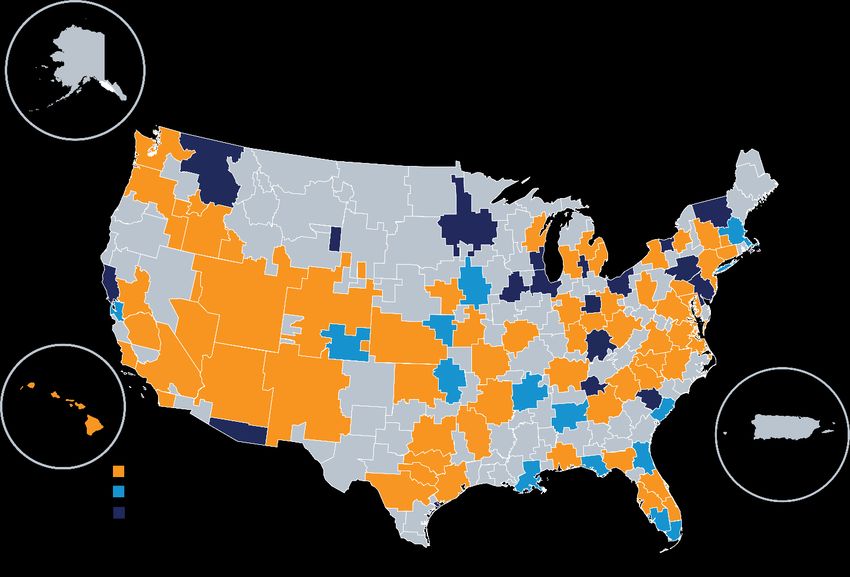
Current ATSC 3.0 Market Coverage

 Source: atsc.org
 7

ATSC 3.0 Coverage at Full UHF Deployment
 • Only 696 UHF
 towers separated
 by at least 1km are
 considered

 • 830 UHF and 516
 VHF towers are
 excluded for
 analysis

 • Thousands of low
 1-3 stations power stations are
 4-6 also excluded
 7-10
 >10

 8

Redundant Timing Sources
 GPS

 PTP/fiber
 Redundant
 time Reference Time
Atomic clock (cesium/rubidium)
 keeping
 system
Neighboring ATSC 3.0 TV stations

 eLoran
 9

Increasing Resiliency and Accuracy
 f2 f3

 Report emission time and location of
 f4 neighboring stations
f1
 Report timestamping errors of
 previous frames
 fn

 10
Advantages of BPS
Infrastructure is already built; can be deployed with low incremental cost
Reliable Tx facility designed to continue to operate during emergencies
Frequency diversity (wide range of frequencies)
In-building coverage (high-power, high-tower)
Works when GPS is spoofed or unavailable
Free to use
Receiver chip-sets are mass produced
Handles unlimited number of users
 11
Use Cases

Deliver GPS-independent time

Deliver GPS-independent position and time

Detect GPS spoofing

GPS-BPS hybrid location, DGPS/RTK, A-GPS Assistance data

 12
Development Phases
 Phase 1 Phase 2 Phase 3 Phase 4 Phase 5 Phase 6
2022-2023 2023-2024 2024-2025 2025-2027 2026-2027 2027-2029

 Build
 Modify Add backup Deploy ATSC 3.0 Add neighbor
 Build Tx-side multilateration
 equipment/soft timing sources based timing for measurement
 prototype receiver
 ware as needed at Tx site use by the public features
 prototype

 Deploy BPS
 Demonstrate Demonstrate Set up a test
 Deploy in a live Fund system (time and
 ATSC 3.0 time delivery in area with four
 market operations position) for use
 compliance a live market TV towers
 by the public

 Demonstrate
 Build a
 Identify joint positioning Fund system
 prototype
 technology gaps and timing use operations
 receiver
 case

 Demonstrate
 Measure timing Plan for future
 timing at a
 accuracy improvement
 known location
 13
Phase 1 – Funded by NAB
BPS Time Stabilization
 System Control

 1 Receiver
 2 HTTP, WebSocket Coax
 Antenna
 Avateq
 6
 AVQ 1022(1st Gen)
 HTTP RF Layer Monitoring Receiver

 3 4 5
 STLTP Coax
 Triveni Digital GatesAir
 Broadcast Gateway Maxiva XTE Exciter Transmitter
 (Atbis OEM)
 14
PEP: Example of Broadcaster-Gov’t Partnership

 • Executive Order 13407 -
 Public Alert and Warning
 System

 • FEMA Primary Entry Point
 (PEP) Stations

 • ATSC 3.0 supports
 Emergency Alert System
 (EAS)

 15
Government Support for Free-to-use Service

 Develop public-private partnership

 Fund R&D for Phase 4 Phase 5 Phase 6
Phases 2 and 3
 Deploy time use Test in live Deploy time and
Demonstrate in a case nationwide markets position use case
 live market nationwide

 16
Questions?

 17
Thank You

 18
BACKUP SLIDES

 19
ATSC 3.0 Signal
 Payload- tower location,
 Bootstrap – time of Preamble – time neighbor measurements,
arrival (TOA) estimation information and past measurement
 errors

 Source: ATSC Standard, Physical Layer Protocol, Doc. A/322:2020 20
Preamble Timestamp

Source: ATSC Standard, Physical Layer Protocol, Doc. A/322:2020 21
Time Synchronization at the Transmitter
 GPS
 Antenna TV Antenna
 Measured
 timing error Timing error measurement
 Loop
 device with demodulator
 filter
 and GPS

 Smoothed
 error
 Preamble timing
 adjustment circuitry TV Tower
 and software

 Analog delay (DAC,
 Digital delay
 Preamble amplifiers, filters,
 (software and
 generator transmission line,
 hardware)
 etc.)
 22
Coverage Assumptions
 Parameter Value Unit
• System System Bandwidth 6 MHz
 threshold -5 dB Thermal Noise (kTB) -106.2 dBm
 SNR (Data PLP
 is the weakest Frequency of Operation 539 MHz
 link) Antenna Gain 0 dBi
• Longley–Rice Antenna Factor -129.6 dBm-dBµV/m
 propagation
 model is used Noise Figure 6 dB
 Required Field Strength 24.4 dBµV/m
 RX Antenna height, AGL 1.5 m
 Location, Time Variability 50%, 50% –
 23
Approximate BPS Coverage Area (CONUS) # Stations Cell Count Cumulative Fraction of CONUS 10 40969 53% 9 43235 56% 8 45854 60% 7 48801 63% 6 52038 68% 5 55794 72% 4 60232 78% 3 65606 85% 2 71264 93% 1 76076 99% Total CONUS Land Area 77000 (100% = 7.7 million km2) 24
Pseudorange Multilateration Concept

 Pseudorange equations:
 d2 1 = 1 − 2 + 1 − 2 +
 d1
 (x2,y2) 2 2
 2 = 2 − + 2 − +

(x1,y1) 3 = 3 − 2 + 3 − 2 +
 d3

 (x,y)
 t: receiver clock offset
 c: speed of light

 (x3,y3) 25
Multilateration Technique
• (x̂,ŷ) is the estimated location of the receiver
• t ̂ is the estimated clock offset
• r̂1, r̂2, and r̂3 are the estimated pseudoranges

 = ො + 1 = 1Ƹ − 1
 = ො + 2 = 2Ƹ − 2
 = Ƹ + 3 = 3Ƹ − 3

 26
Multilateration Iterative Solution
 1 − ො 1 − ො
 1
 1 − ො 2 + 1 − ො 2 1 − ො 2 + 1 − ො 2
 2 − ො 2 − ො 1
 = = 1 = 2
 − 2 − ො 2 + 2 − ො 2 2 − ො 2 + 2 − ො 2
 3
 − ො − ො
 1
 3 − ො 2 + 3 − ො 2 3 − ො 2 + 3 − ො 2

 Least-square solution: = ( )−1
 1 ⋯ 0
Weighted least-square solution: = −1
 where = ⋮ ⋱ ⋮
 0 ⋯

 27
Simulation Set-up

4 towers at (50000, 0), Random TOA estimation Unresolved multipath Receiver clock offset is
(0, 50000), (-50000, 0), error between -5 m to error at the receiver set to the distance of the
and (0, -50000) meters on +5 m (uniform dist.) 0-100 m (uniform dist.) nearest tower
X-Y plane
200 m antenna height Standard deviation well Assumed that TOA Assumed that receiver
 above Cramer-Rao bound detector will detect the clock will synchronize with
 Bootstrap sample earliest path the strongest signal
 duration is 48.8 m Assumed that ambiguity
 function based joint time-
 frequency estimation

 28
A Typical Simulation Run

TOA estimation error: 4.1 m, -3.2 m, -2.4 m, -3.5 m,
multipath error: 13.6 m, 86.9 m, 58.0 m, 55.0 m,
clock offset: 25495.9 m

true (x,y,t): x = -25000.0 m, y = -5000.0 m, t = 25495.9 m
estimated (x,y,t): x = -24989.9 m, y = -5015.7 m, t = 25549.6 m

estimation error: x = -10.1 m, y = 15.7 m, t = -53.7 m
estimation error (distance): 18.7 m

 29
A Typical Simulation Run

 30
Simulation of 10,000 Points

 31
Simulation Results of 10,000 Points

 32
Increasing Yield, Resiliency, and Accuracy

 System threshold can be reduced to -9 dB SNR (preamble) if neighbor
 stations report all nearby neighbor antenna locations

 System threshold can be reduced to -12 dB SNR (bootstrap) if neighbor
 stations report all neighbor antenna locations, timing, and frequency

 Accuracies of previous fixes can be improved if timestamping error of the
 previous frame is sent on the next data frame

 33
Recommended Neighbor Measurements
• Transmit antenna ID (a unique ID to distinguish the antenna)
• Transmit antenna position (latitude, longitude, and elevation)
• Transmit antenna radiated power
• Transmit antenna radiation pattern (and/or average coverage radius)
• Neighbor station antenna IDs
• Neighbor station channels (frequencies)
• Neighbor antenna positions (latitudes, longitudes, and elevations)
• Neighbor antenna radiated power levels
• Neighbor antenna radiation patterns
• Timing offset of the neighbor bootstrap signals relative to the self bootstrap signal
– Could either be the value observed at the self (transmitter) site or can be compensated for the distance travelled
• Current number of leap seconds expressed as TAI – UTC
– To avoid decoding of A/331 video service messages for location computation
• Reported bootstrap transmission time of the previous frames (for both self and neighbors)
• Measured time-stamp reporting error of the previous frames (for both self and neighbors)

 34
You can also read