Bottleless Point-of-Use Water Dispenser - Single Stage Filtration System Owner's Manual
←
→
Page content transcription
If your browser does not render page correctly, please read the page content below
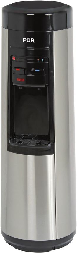
Bottleless Point-of-Use
Water Dispenser
Single Stage Filtration System

Owner’s Manual
P1QC7506BLS

          Includes
Quick-Connect Filter

                                                                                 © 2020 All rights reserved.
                                 PUR is a registered trademark used under license from Helen of Troy Limited.
                                                                                                     200908
Table of Contents:

Safety Precautions ................................................................... 1      Operation Instructions.......................................................8 - 10
Pre-Operation............................................................................ 2      * Child Resistant Safety Switch........................................... 8
   * Grounding Precautions...................................................... 2               * Dispensing Hot Water........................................................ 9
   * Specifications.................................................................... 2        * Dispensing Cold Water....................................................... 9
Water Dispenser Layout and Components................................. 3                         * Adjusting the Cold Water Temperature............................... 9
Installation Instructions.......................................................4 - 7         Cleaning and Maintenance..............................................10 - 11
   * Copper Pipe Plumbing....................................................... 4               * Cleaning the Drip Tray..................................................... 10
   * Flexible Pipe Plumbing...................................................... 4              * Cleaning the Outside of the Dispenser............................ 10
   * Installation Location.......................................................... 5           * Internal Reservoir Overflow Protection............................. 10
   * Water Line Hook-Up......................................................5 - 6               * Draining the Reservoirs................................................... 10
   * Filter Installation............................................................... 6        * Going Away on Vacation................................................... 10
   * Water Leakage Detection System....................................... 7                  Performance Data Sheet..................................................10 - 11
   * Filter Replacement............................................................ 7         Troubleshooting Guide............................................................. 11
Initial Product Cleaning.......................................................7 - 8          Warranty.................................................................................. 12

Safety Precautions:

• IMPORTANT: Refrigerants must be handled and disposed of by qualified service personnel only. Before discarding this water
  dispenser to landfill, contact local authorities for advice on proper disposal methods for refrigerants.
• This Water Dispenser is designed for “indoor” use only. DO NOT USE OUTDOORS.
• Never turn the dispenser upside down or tilt more than 45 degrees. During transportation, if the dispenser was transported
  sideways, the unit must be left to stand upright for 12 hours before connecting to power source and initiating operation.
• This Water Dispenser is equipped with a grounded power cord and plug for your safety.
• Keep your Water Dispenser in a dry place away from any heat source and direct sunlight.
• Never put anything flammable close to the dispenser.
• Leave a minimum of 2” (5cm) around the back and sides of the dispenser for proper ventilation.
• Always install your Water Dispenser on a level, solid floor.
• Wait 3 minutes before restarting dispenser after shutting it down.
• Always unplug (disconnect) the Water Dispenser power cord before servicing, cleaning and filter replacement.
• Service must be performed by qualified/authorized service personnel only. Service information is available through our
  Customer Service Department at 1-877-447-4768 or e-mail customerservice@ghpgroupinc.com.
• Regular cleaning of your Water Dispenser is required for your warranty.
• Please follow the cleaning and maintenance instructions outlined in this manual. Cleaning should be done every 4 ~ 6 months.
• It is your responsibility to ensure that all water line connections are properly connected and sealed and there are no system
  water leaks before operating the unit.
• Although this unit incorporates provision of a hot water “child resistant safety switch," never allow children to dispense hot
  water without proper and direct supervision.
• Only use original PUR filters with this unit. (Part # PQCCRB).

DANGER: The hot water in this dispenser is heated to approximately 90°C (194°F).
Temperatures above 52°C (125°F) can cause severe burns from scalding.

1
Pre-Operation:

Grounding Precautions:

WARNING: Failure to follow these instructions can result in death, fire or electrical shock.

• This appliance must be grounded. In the event of an electrical short circuit,
  grounding reduces the risk of electric shock by providing an escape wire for
  electric current.
• Improper use of the grounding plug can result in a risk of property damage,
  electric shock causing serious injury, and even death.
• This appliance is equipped with a power cord having a grounding wire with a
  grounding plug and must be connected into a properly grounded polarized outlet.
  Consult a qualified electrician if the grounding instructions are not completely
  understood, or if doubt exists as to whether the wall outlet is properly grounded.
• If the wall outlet is a standard 2 prong outlet, it is your personal responsibility
  and obligation to have it replaced with a properly grounded 3-prong wall outlet.
• Do not under any circumstances cut or remove the third (ground) pin from the
  power cord plug.
• Do not use adapter plugs or extension cords with this appliance.
• If the power cord is too short, have a qualified electrician install an electrical
  outlet near the appliance.
• Do not use the appliance if the power cord becomes frayed or otherwise damaged.
• A 115 Volt, 60 Hz., AC only 15 amperes fused, grounded electrical supply is
  required. It is recommended that a separate circuit serving only your Water
  Dispenser be provided. Use an outlet that cannot be turned off by a switch.

Specifications:

 P1QC7506BLS

 Heating Temp (approx.):             194°F/90°C

 Cooling Temp (approx.):             39-54°F/4-12°C

 Min./Max. Working Water Pressure:   30-100 psi

                                     Hot                     Cold
 Output per Hour:                    1.22 gal / 4.6 L        0.53 gal / 2.0 L

 Internal Tank Capacity:             0.16 gal / 0.6 L        0.95 gal / 3.6 L

 Power Consumption:                  1150W                   88W

                                                                                               2
Water Dispenser Layout and Components:
P1QC7506BLS
Front Back
1
2 5
3 6
4
9
10
7
11
8
12
13
14
Item Description Item Description
1 Top Cover 9 Drain Valve
2 Kettle Feature Activation Button 10 Adjustable Cold Water Thermostat
3 Hot/Room Temperature Water Dispensing Button 11 Water Inlet & Manual Shut-off Valve
4 Child Resistant Safety Switch 12 Condenser Coils
5 Ready-To-Dispense Indicator Lights 13 Filter Head (Factory Installed)
6 Cold Water Dispensing Button 14 Carbon Block Filter (Part # PQCCRB)
7 Removable Drip Tray
8 Lower Front Panel
3Installation Instructions:
WARNING: It is highly recommended to have your Water Dispenser installed by a licensed plumber. If you are
installing the Water Dispenser yourself, the following information is important: It is your personal responsibility
to adhere to all Governing State, Federal, Provincial and Local Plumbing Code Regulations.
Depending on the type of plumbing in your home (copper or flexible pipe), the following plumbing installation accessories
(not included with the Water Dispenser) will be required to complete the installation of your Water Dispenser. These items can be
purchased at your local hardware store.
Copper Pipe Plumbing (Soldering Required):
(A) 1/2” Copper Tee (B) 1/2” Male Solder x (C) Installation Appearance
1/4” OD Compression
Fitting Shut-Off Valve
Tools Required
• Soldering flux • Copper tube/pipe cutter
• Solder • Welding torch
• Emery cloth • Towels (water clean-up)
Flexible Pipe Plumbing (No Soldering or Glue Required):
(D) 1/2” x 1/2” x 1/2” (E) 1/2" Quick-Grip x 1/4" (F) Installation Appearance
Quick-Grip Tee OD Compression Fitting
Shut-Off Valve
Tools Required
• Plastic pipe/tube cutter
4Installation Instructions (continued):
Installation Location:
Select a suitable location where the Water Dispenser will be installed, making sure you have easy access to an electrical wall outlet
and the household cold water supply line.
Figure 1A
Water Line Hook-Up:
1. IMPORTANT: Turn off the household cold water supply line.
2. Open the cold water faucet allowing water to purge the system to minimize water leakage cleanup.
3. COPPER PIPE PLUMBING: Using a tube/pipe cutter, cut and remove a section of the cold water
line at the desired height. Cut should be made above any manual shut-off valve installed on the
water line.
4. Using an emery cloth, clean the ends of the copper pipes and apply a liberal layer of flux to both
the inside of the fitting and the outside of the pipe before sliding the two parts together that are
being soldered. Follow manufacturer’s installation instructions provided with the 1/2” Male Solder Valve Open
x 1/4” OD Compression Fitting Shut-Off Valve (B).
5. FLEXIBLE PIPE PLUMBING: Using a tube/pipe cutter, cut and remove a section of the cold water
line at the desired height. Cut should be made above any manual shut-off valve installed on the Figure 1B
water line. Follow manufacturer’s installation instructions provided with the 1/2” x 1/2” x 1/2”
Quick-Grip Tee (D) and 1/2” Quick-Grip x 1/4” OD Compression Fitting Shut-Off Valve (E).
6. Close the newly installed Shut-Off Valve (Figure 1A and Figure 1B) and slowly re-open the cold
water supply line and check for leaks. If leaks are detected, immediately turn off the water supply
and repair any leaks. If no leaks are detected, proceed to step 7.
7. The Water Dispenser includes 1.8 meters (6 feet) of 1/4” OD Flexible Tubing. If additional
Tubing is needed, it can be purchased at your local hardware store. Cut the desired length to
suit your installation requirements, making sure both ends of the Tubing are cut straight/square
(Figure 1 & Figure 2). Remove the Compression Nut and Ferrule from the Valve and install them
onto the Tubing (Figure 3). Insert the Tubing into the Valve until it stops (Figure 4). Slide both the Valve Closed
Compression Nut and Ferrule toward the Valve and tighten the Compression Nut firmly using a
wrench (Figure 5). DO NOT OVERTIGHTEN.
Figure 1 Figure 2 Figure 3
Figure 4 Figure 5 Figure 6
5Installation Instructions (continued):
8. The Water Dispenser is equipped with a Manual Shut-Off Valve installed on the rear of Figure 7
the unit (Figure 6) for easy access in case of an emergency. Remove sanitation plug
from the Shut-Off valve before installing the water line (Figure 7).
9. Connect the incoming water line into the open side of the Manual Shut-Off Valve
(Figure 6). This valve utilizes Quick-Connect Fittings, for which no tools are required. Sanitation Plug
Simply insert the end of the Tubing firmly into the Manual Shut-Off Valve until it
comes to a complete stop (approx. 1/4”) (Figure 8).
WARNING: DO NOT OPEN THE COLD WATER SUPPLY VALVE AT THIS STAGE.
(See Installation of Filter) Figure 8
Backstop
To disconnect the Tubing from the Manual Shut-Off Valve, you must first remove the Blue
"Horseshoe C-Clip” from the Quick-Connect Fitting (Figure 9). Then push in the Collet and
pull out the Tubing to remove it from the Manual Shut-Off Valve (Figure 7).
NOTE: The Blue "Horseshoe C-Clip” must always be installed PRIOR to
installation of the water lines.
Full engagement length
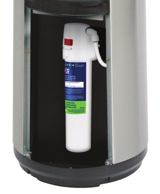
Filter Installation (See Figure 10 & 11): Figure 9
O-Ring
The Filter inside the Water Dispenser has not been factory installed. It has been shipped
in its original shrink-wrapped packaging for sanitation purposes.
The Filter is located behind the Lower Front Panel of the Dispenser. Follow these steps to
access/install the Filters:
1. Pull out the Drip Tray and then remove the Phillips Screw securing the Lower Panel.
Remove the Lower Panel from the Dispenser (Figure 10). Collet
Horseshoe Clip
2. Remove the Filter from the Retaining Clip, and remove the shrink-wrap.
3. Check that the Red Locking Tab (filter head) is positioned to the left “Unlock” position Figure 10
(Figure 11).
4. Insert the Filter into the Filter Head and give it a 1/4 turn clockwise until it stops and
the dots are properly aligned. Push the Red Locking Tab to the right “Locked” position
(Figure 11). If the Red Locking Tab fails to engage (lock), the Filter is not sufficiently
aligned. Make sure the dots on the filter head and filter are properly installed/aligned.
NOTE: The internal water connection lines to the Filter Head are factory
installed. Figure 11
The installation is now complete. Slowly open the Shut-Off Valve. Check all connections
for leaks prior to opening all water valves fully. If any leaks are detected, immediately
turn off the water supply and repair. Re-install the lower front panel and secure with
Phillips screw and then re-install the drip tray (Figure 10).
1/4
45˚
6Installation Instructions (continued):
Water Leakage Detection System: Figure 12a
This Water Dispenser is equipped with a low voltage water leakage detection system
located inside the base of the filter compartment and is covered by a removable drip tray
(Figure 12a). In the event any water makes contact with the leakage detection system,
an audible alarm will sound continuously until the water is removed. Upon activation
of the leakage detection system, the water inlet solenoid valve (located internally) is Figure 12b
automatically deactivated suspending incoming water activity until the alarm is silenced.
To silence the alarm, all accumulated water surrounding the sensors (Figure 12b),
must be removed using a sponge and/or paper towels. The water inlet solenoid valve
reactivates automatically once the alarm is silenced.
Filter Replacement:
For optimum water efficiency and performance, we recommend replacing the filter every 6 months. Replacement filters can be
ordered on-line at: www.ghpgroupinc.com. Use only original PUR filters with this unit. (Part # PQCCRB)
CAUTION: Before replacing the filters, always turn off the water supply using the manual shut-off valve located
at the rear of the dispenser. This will depressurize the water line and minimize water overspray when the filter
is released. Remove and empty drip tray of any accumulated water found under the filter. If the audible alarm
sounds, refer to “WATER LEAKAGE DETECTION SYSTEM” instructions.
Initial Product Cleaning:
Like most appliances, your Water Dispenser requires periodic maintenance for Figure 13
maximum efficiency and performance. It must be cleaned on a regular basis,
(coincide with filter replacement i.e. every 6 months) in order to maintain a
hygienic environment and prevent potential bacteria growth.
1. Always disconnect (unplug) the power cord before attempting any cleaning,
maintenance and filter replacement.
2. Before attempting any cleaning, maintenance and/or filter replacement,
always turn off the water supply using the manual shut-off valve at the rear of
the dispenser.
Figure 14
3. To access the reservoir system, you must remove the top cover on the
dispenser by removing the two Phillips screws located at the rear of the cover
(Figure 13).
4. Carefully lift off the top cover. This may require using a little force.
5. Remove the reservoir cover by carefully pulling upward (Figure 14).
6. Fill the reservoir with a pre-mixed solution of 15ml (1 tbsp) white vinegar with
3.0L (0.79 gal) of hot water and let stand for 20 min (Figure 15).
7. Place a jug under both hot and cold spigots and press both taps until the Figure 15
cleaning solution stops flowing (Figure 16).
15ml (1 tbsp)
8. Flush the reservoir with clean water and press both dispensing taps until vinegar
water stops flowing. 3.0L (0.79 gal)
hot water
7Initial Product Cleaning (continued):
9. T o drain any remaining water from the reservoirs, unscrew the drain cap and Figure 16
plug located at the rear of the dispenser (Figure 17). Collect the water into a
bucket. Flush the reservoir a second time with clean water.
IMPORTANT: Remember to re-install and tighten the drain cap and the plug.
10. Re-install the reservoir cover by pressing down firmly.
11. Re-install the dispenser top cover and secure using the two Phillips screws.
12. Re-connect the power cord.
13. Re-open the manual shut-off valve. You will hear water entering the system
which will stop automatically when the appropriate water levels are reached. Figure 17
14. Place a container under the water spigots and press both dispensing buttons
(separately) to make sure water is flowing normally from each side.
Operation Instructions:
IMPORTANT NOTE: Your PUR® Water Dispenser is designed with a special safety feature (float switch
mechanism) that controls the operation of the Kettle Feature hot water tank heating system.
If no water is present and/or low water levels are detected inside the internal reservoir system, operation of the hot water heating
system is not possible. Likewise, if the hot water heating is operational and water is being drawn simultaneously causing water levels
to drop below safe levels, hot water tank operation is automatically terminated until normal water levels are restored, at which time
you must “manually” re-activate the hot water heating system by pressing the Kettle Feature (red) button (Figure 20).
NOTE: Operation of the cold water system is not affected by this safety feature.
Child Resistant Safety Switch (See Figure 18 & 19): Figure 18
CAUTION: Do not allow children to use the hot water dispensing button
without proper and direct supervision.
To prevent hot water from being dispensed accidentally and possibly harming a child,
the hot water dispensing button can only be operated when the child resistant safety
switch is activated. To dispense hot water, slide the child safety switch sideways and
hold (in the direction of the arrow located on the switch) from right to left (Figure 18),
then press/hold the hot water button (Figure 19). As soon as water starts flowing
you can release the child safety switch until the desired amount of hot water is
dispensed. Upon releasing the hot water button, the child safety switch automatically Figure 19
re-engages to the locked position.
8Operation Instructions (continued):
Dispensing Hot Water (See Figure 20): Figure 20
WARNING: The hot water is heated to approximately 90°C (194°F).
Temperatures above 52°C (125°F) can cause severe burns from scalding.
The Kettle Feature (hot water) dispensing system on this unit is designed to save
energy and money. Conventional hot water dispensing systems operate 24/7 regardless
of water usage. The on demand Kettle Feature activates the hot water system only
when the Kettle Feature (red) button is activated delivering steaming hot water within
3 minutes. To stop/cancel the Kettle Feature during a cycle, simply press the Kettle
Feature (red) button a second time and the red LED light will turn off.
1. Press the Kettle Feature (red) button and the red LED light will start flashing to signify the heating system is operational.
The heating cycle takes approximately 3 minutes. When the heating cycle is completed, the red LED light will change from
“flashing” to a steady “on” condition, meaning water has reached optimum temperature and is ready for dispensing.
2. To dispense hot water, place cup/glass under dispensing spigot, push/hold the child safety switch to the left and press the
hot water dispensing button (with red line indicator), until the desired amount of water is dispensed. The red LED light will
turn off automatically as hot water is dispensing.
NOTE: The hot water temperature (factory default setting) is not adjustable on this unit.
Dispensing Cold Water:
The cooling system on this unit is designed to activate automatically as soon as the power cord is connected.
1. When the blue LED light is “off” the cooling cycle is operational. When the blue LED is light is “on” the cooling cycle
(compressor) is off and the cold water has reached optimum temperature.
2. To dispense cold water, place cup/glass under dispensing spigot, push/hold the cold water dispensing button (with blue line
indicator) until the desired amount of water is dispensed.
NOTE: This Water Dispenser left the factory with the cold water temperature control default setting positioned for Energy
Star compliance (Figure 21). This setting will deliver cold water temperatures between 8°C - 10°C (46°F - 50°F).
Adjusting the Cold Water Temperature (See Figure 21): Figure 21
The temperature of the cold water reservoir is monitored by a cold water control
located at the rear of the dispenser. By turning the thermostat set screw (Figure 21)
the temperature can be adjusted. Using a screwdriver, turn the dial clockwise between Thermostat
“L” (lower setting for warmer water) and “H” (higher setting for colder water) until the Set Screw L H
desired temperature is reached. If water is not being properly dispensed, there could
be possible ice build-up in the reservoir due to the thermostat being set too cold. If this
happens, slowly rotate the thermostat set screw counterclockwise to a warmer setting.
NOTE: Any change to the cold water temperature control may effect Energy Star efficiency.
Cleaning and Maintenance:
Cleaning the Drip Tray (See Figure 22): Figure 22
NOTE: The drip tray is NOT dishwasher safe.
To remove, pull the drip tray towards you. Drain and clean. The drip tray should be
emptied and cleaned regularly to remove spotting and mineral deposits.
Clean with a mild soap and water mixture. For tough deposits, add vinegar and let
soak until the deposits come loose. Then wash, rinse and dry thoroughly. Put the grill
back on the tray and install on the dispenser.
9Cleaning and Maintenance (continued):
Figure 23
Cleaning the Outside of the Water Dispenser:
The outside of the dispenser can be wiped clean using a mild soap and water
mixture. Never use harsh chemicals or abrasive cleaners. Rinse thoroughly with
clean water and then dry surfaces. Condenser
Vacuum or sweep away the dust from the condenser coils (Figure 23) at the back of Coils
the dispenser. Keeping the condenser coils clean improves cooling efficiency.
Internal Reservoir Overflow Protection:
Figure 24
The internal (cold tank) reservoir incorporates a water overflow flotation device
(Figure 24). The operating parameter of this device allows the float to move freely
“up/down” according to related water levels. As water levels rise, so does the float
causing the water inlet valve to close at a pre-determined level. As water levels fall,
so does the float causing the water inlet valve to open allowing replenishment of
incoming water.
Draining the Reservoirs:
Figure 25
IMPORTANT! Unplug the dispenser before performing this procedure.
Dispense hot water until temperature drops to a safe level to avoid the
risk of scalding.
1. Turn off the water supply, using manual shut-off valve at the rear of the dispenser.
2. Press both dispensing buttons until water stops flowing (Figure 25).
3. Place a bucket beneath the drain valve located at the rear of the
dispenser (Figure 26).
4. Remove the drain cap and plug from the drain valve and let the remaining water
flow into the bucket. Figure 26
5. Replace the cap and plug.
Going Away on Vacation:
When not using the dispenser for long periods of time or when going on vacation,
unplug the dispenser and drain the reservoirs (See Draining the Reservoirs above).
Follow Initial Product Cleaning Procedures upon return, found on page 7.
Performance Data Sheet:
Note: Read this performance data and compare the capability of this system with your actual water treatment
needs. It is recommended that, before installing the system, you have your water supply tested to determine
your actual water treatment needs.
This system conforms to NSF/ANSI 42 for the specific performance claims as verified and substantiated by test data. While testing
was performed under standard laboratory conditions, actual performance may vary.
The PQC1FS system has been certified by NSF International according to NSF/ANSI 42 and CSA B483.1 for the reduction of
substances listed below. The concentration of the indicated substances in water entering the system was reduced to a
concentration less than or equal to the permissible limit for water leaving the system as specified in NSF/ANSI 42.
10Performance Data Sheet (continued):
PQC1FS with PQCCRB Filter
Average Influent
Percent Reduction Percent Reduction
Substance Challenge
Requirement 1
Concentration
NSF Standard 42
Chlorine 2.0 mg/L ± 10% ≥ 50% 91.8%
Particulate Class III 10,000/mL ≥ 85% 99.9%
Flow Rate =1 gpm (3.78 lpm) Capacity = 1,000 gallons (3,780 L) or 6 months
1 Tested by NSF International according to NSF/ANSI Standard 42 and CSA B483.1.
Troubleshooting Guide:
Problem Possible Cause Solution
Check all water line connections for Repair water line connections and make sure blue locking “Horseshoe
leaks c-clips” are installed on water lines.
Water dispenser is leaking Filter not properly secured and locked Secure filter and lock.
Drain cap and plug are not secure Ensure drain plug is secure and tighten drain cap.
Insufficient water levels in the reservoir Make sure all water shut-off valves are open.
The unit is unplugged Plug in the power cord.
No hot water
Kettle Feature button was not activated Activate the Kettle Feature button.
The temperature limit switch will re-set automatically when the
Temperature limit switch tripped
temperature of the water drops.
The circuit breaker in your home is
Reset the breaker or replace the fuse.
tripped or the fuse is blown
No cold water The unit is unplugged Plug in the power cord.
Cold water control needs to be Adjust cold water control between L (warm) and H (colder) levels to
adjusted colder achieve desired temperature.
Water dispenser is not dispensing
Water shut-off valves are closed Open all water shut-off valves.
water
Water leakage detection system is
Alarm is beeping continuously Refer to Water Leakage Detection System instructions in the manual.
activated
Attention: Do not return this product to the store.
Should service be required or you have any questions regarding how to use your PUR product, please contact Customer Service at:
1-877-447-4768 or customerservice@ghpgroupinc.com
Manufactured and warranted by GHP Group Inc.
USA: 6440 W. Howard St. Niles, IL 60714-3302
Canada: 271 Massey Rd. Guelph, Ontario, N1K 1B2
11Warranty:
Limited Warranty:
This limited warranty is extended to the original retail purchaser of this water dispenser and warrants against any defect in material and workmanship for
a period of one (1) year from the date of retail sale. GHP Group, Inc., at its option, will either provide replacement parts or replace the unit, when properly
returned to the retailer where purchased within one (1) year of retail purchase. (Shipping costs, labor costs, etc. are the responsibility of the purchaser.)
Duties of the Owner:
This water dispenser must be installed and operated in accordance with the written instructions furnished with this unit. This warranty shall not excuse
the owner from properly maintaining this unit in accordance with the instructions. A bill of sale, canceled check or payment record must be kept to verify
purchase date and establish warranty period. Original carton should be kept in case of warranty return of the unit.
What is Not Covered?
• Service trips to your home to teach you how to use the product.
• Improper installation, delivery, or maintenance. Failure to maintain the product according to the instructions outlined in the product manual will
automatically void the warranty.
• Failure of the product if it is abused, misused, altered, used commercially, or used for other than the intended purpose.
• Products that are used outside a residential or office environment.
• Replacement of house fuses or resetting of circuit breakers.
• Use of this product where water is microbiologically unsafe or of unknown quality.
• Damage to the product if used to dispense anything other than water.
• Damage to the product caused by accident, fire, floods, or acts of God.
• Any service to the product by unauthorized personnel.
• Incidental or consequential damage caused by possible defects with this appliance, its installation or repair.
THIS LIMITED WARRANTY IS GIVEN TO THE PURCHASER IN LIEU OF ALL OTHER WARRANTIES, EXPRESSED OR IMPLIED, INCLUDING BUT NOT LIMITED TO THE
WARRANTIES OF MERCHANTABILITY OF FITNESS FOR A PARTICULAR PURPOSE. THE REMEDY PROVIDED IN THIS WARRANTY IS EXCLUSIVE AND IS GRANTED IN
LIEU OF ALL OTHER REMEDIES. IN NO EVENT WILL GHP GROUP. INC. BE LIABLE FOR INCIDENTAL OR CONSEQUENTIAL DAMAGES.
Some states/provinces do not allow limitations on how long an implied warranty lasts, so the above limitation may not apply to you. Some states/provinces
do not allow the exclusion or limitation of incidental or consequential damages so the above limitation or exclusion may not apply to you.
Claims Handled as Follows:
1. Contact your retailer and explain the problem.
2. If the retailer is unable to resolve the problem, contact our Customer Service Dept. detailing the system model, the problem, and proof of date of purchase.
3. A representative will contact you. DO NOT RETURN THE UNIT TO GHP GROUP, INC. unless instructed by our Representative, or with written authorization.
This warranty gives you specific legal rights and you may also have other rights that vary from state/province to state/province.
Product Registration:
To register your product, please visit: ghpgroupinc.com/product-registration.html and complete within (14) days of purchase.
After handling the electrical power cord,
please wash your hands
Warning: This Product can expose you to
chemicals including Diisononyl phthalate (DINP)
which is known to the State of California to
cause cancer and Di-isodecyl phthalates (DIDP)
which is known to the State of California to
cause birth defects or other reproductive harm.
For more information go to:
www.p65Warnings.ca.gov
12Product Notes: 13
Distributeur d’eau sans bouteille
branché à la canalisation
Système de filtration à une seule étape

Manuel du
propriétaire
P1QC7506BLS

 Filtre à connexion
       rapide inclus

                                                                                                                       © 2020 Tous droits réservés.
                               PUR est une marque déposée dont l’utilisation est autorisée en vertu d'une licence accordée par Helen of Troy Limited.
Table des matières :
Précautions de sécurité .......................................................... 15 Mode d’emploi..................................................................22 - 24
Avant l’installation.................................................................. 16 * Interrupteur de sécurité-enfants..................................... 22
* Précautions de mise à la terre......................................... 16 * Distribution de l’eau chaude........................................... 23
* Caractéristiques.............................................................. 16 * Distribution de l’eau froide.............................................. 23
Configuration et composants du distributeur d’eau ............... 17 * Réglage de la température de l’eau froide....................... 23
Instructions d’installation................................................18 - 21 Nettoyage et entretien......................................................24 - 25
* Installation pour plomberie en cuivre.............................. 18 * Nettoyage du plateau d’égouttement............................... 24
* Installation pour plomberie flexible................................. 18 * Nettoyage de l’extérieur du distributeur........................... 24
* Emplacement de l’installation......................................... 19 * Protection anti-débordement du réservoir interne........... 24
* Raccordement de la conduite d’eau.........................19 - 20 * Vidange des réservoirs.................................................... 24
* Installation du filtre........................................................ 20 * Partir en vacances........................................................... 24
* Système de détection des fuites d’eau............................ 21 Fiche de données sur la performance...............................24 - 25
* Remplacement du filtre................................................... 21 Guide de dépannage............................................................... 25
Nettoyage initial de l’appareil..........................................21 - 22 Garantie.................................................................................. 26
Précautions de sécurité :
• IMPORTANT: Les réfrigérants doivent être manipulés et éliminés uniquement par un personnel d’entretien qualifié. Avant
de jeter ce distributeur d’eau à la décharge, contactez les autorités régionales pour obtenir des conseils sur les méthodes
d’élimination appropriées des produits réfrigérants.
• Ce distributeur d’eau est conçu uniquement pour une utilisation « à l’intérieur ». NE PAS UTILISER À L’EXTÉRIEUR.
• Ne tournez jamais le distributeur à l’envers ni ne l’inclinez à plus de 45 degrés. Si le distributeur a été transporté sur le côté,
veuillez garder l’appareil debout pendant 12 heures avant de le brancher à une source d’alimentation et de le mettre en
marche.
• Ce distributeur d’eau est équipé d’un cordon d’alimentation et d’une prise mise à la terre pour votre sécurité.
• Gardez votre distributeur d’eau dans un endroit sec loin de toute source de chaleur et de lumière directe du soleil.
• Ne jamais poser d’objets inflammables près du distributeur.
• Laissez un dégagement minimum de 2 po (5 cm) derrière le distributeur et sur les côtés du distributeur pour une ventilation
adéquate.
• Installez toujours votre distributeur d’eau sur une surface solide et plate.
• Attendez 3 minutes avant de redémarrer le distributeur après l’avoir éteint.
• Débranchez toujours le cordon d’alimentation du distributeur d’eau avant tout entretien, nettoyage ou remplacement du filtre.
• Le service d’entretien doit être effectué uniquement par du personnel d’entretien qualifié/autorisé. Pour des renseignements
sur ce service, contactez notre service clientèle au 1-877-447-4768 ou par courriel sur customerservice@ghpgroupinc.com.
• Un nettoyage régulier de votre distributeur d’eau est nécessaire pour que votre garantie soit valide.
• Veuillez suivre les instructions de nettoyage et d’entretien décrites dans ce manuel. Le nettoyage doit être effectué tous les 4 à
6 mois.
• Il est de votre responsabilité de vous assurer que tous les branchements des tuyaux d’eau sont correctement reliés et scellés et
qu’il n’y a pas de fuites d’eau dans le système avant d’utiliser l’appareil.
• Bien que cet appareil soit doté d’un « interrupteur de sécurité-enfants » pour l’eau chaude, ne permettez jamais aux enfants
de se servir de l’eau chaude sans une supervision adéquate et directe.
• N’utilisez que les filtres PUR originaux avec cet appareil. (No. de pièce PQCCRB).
DANGER : L’eau chaude de ce distributeur est chauffée à environ 90 °C (194 °F). Des températures
supérieures à 52 °C (125 °F) peuvent causer de graves brûlures.
15Avant l’installation :
Précautions de mise à la terre :
AVERTISSEMENT : Le non-respect de ces instructions peut entraîner la mort, un incendie
ou un choc électrique.
• Cet appareil doit être mis à la terre. En cas de court-circuit électrique, la mise à
la terre réduit le risque de choc électrique en dirigeant le courant électrique vers
la terre.
• Une mauvaise utilisation de la prise de terre peut entraîner un risque de
dommages matériels, de choc électrique causant de graves blessures et même
de la mort.
• Cet appareil est équipé d’un cordon d’alimentation muni d’un fil mis à la
terre et d’une prise mise à la terre et doit être raccordé à une prise polarisée
correctement mise à la terre. Consultez un électricien qualifié si vous ne
comprenez pas toutes les instructions sur la mise à la terre, ou si vous n’êtes
pas certain que la prise murale soit correctement mise à la terre.
• Si la prise murale est une prise standard à 2 broches, il est de votre
responsabilité personnelle et de votre obligation de la faire remplacer par
une prise murale à 3 broches bien mise à la terre.
• En aucun cas, ne coupez ni ne retirez la troisième broche (mise à la terre) de la
prise du cordon d’alimentation.
• N’utilisez pas d’adaptateur ni de rallonges avec cet appareil.
• Si le cordon d’alimentation est trop court, demandez à un électricien qualifié
d’installer une prise électrique près de l’appareil.
• N’utilisez pas l’appareil si le cordon d’alimentation est effiloché ou endommagé.
• Il vous faudra une source d’alimentation de 15 ampères, 115 Volts et 60 Hz mise
à la terre et équipée d’un fusible. Il est recommandé d’utiliser un circuit séparé
qui se branche uniquement à votre distributeur d’eau. Utilisez une prise murale
qui ne peut pas être désactivée par un interrupteur..
Caractéristiques :
P1QC7506BLS
Températures de chauffage (environ) : 194°F/90°C
Températures de refroidissement (environ) : 39-54°F/4-12°C
Min max. Pression d'eau : 30-100 psi
Chaud Froid
Sortie d’eau par heure : 1,22 gal / 4,6 L 0,53 gal / 2,0 L
Capacité interne du réservoir : 0,16 gal / 0,6 L 0,95 gal / 3,6 L
Consommation d’énergie : 1150W 88W
16Configuration et composants du distributeur d’eau :
P1QC7506BLS
Avant Derrière
1
2 5
3 6
4
9
10
7
11
8
12
13
14
Article Description Article Description
1 Le couvercle supérieur 9 Vanne de vidange
2 Bouton d'activation de la fonction bouilloire 10 Thermostat d'eau froide réglable
3 Bouton de distribution d'eau chaude / à température ambiante 11 Entrée d'eau et robinet d'arrêt manuel
4 Interrupteur de sécurité résistant aux enfants 12 Bobines de condenseur
5 Voyants lumineux prêts à distribuer 13 Tête de filtre (installée en usine)
6 Bouton de distribution d'eau froide 14 Filtre de bloc de carbone (pièce # PQCCRB)
7 Plateau d'égouttement amovible
8 Panneau avant inférieur
17Instructions d’installation :
AVERTISSEMENT : Il est fortement recommandé de faire installer votre distributeur d’eau par un plombier
agréé. Si vous installez vous-même le distributeur d’eau, faites attention à ce qui suit: il est de votre
responsabilité personnelle de respecter tous les règlements du Code de la plomberie de l’État ou de
l’autorité fédérale, provinciale ou régionale en vigueur.
Selon le type de tuyauterie installée dans votre maison (tuyauterie en cuivre ou flexible), les accessoires d’installation de
tuyauterie suivants (non fournis avec le distributeur d’eau) seront nécessaires pour terminer l’installation de votre distributeur
d’eau. Ces articles peuvent être achetés dans votre quincaillerie locale.
Installation pour plomberie en cuivre (soudure requise) :
(A) un raccord en T en (B) Une soudure mâle d’un 1/2 po x une (C) Installation finale
cuivre d’un 1/2 po vanne d’arrêt à compression d’un 1/4 po
(diamètre externe)
Outils requis
• Flux de brasage • Tuyau de cuivre/coupe-conduits
• Soudure • Torche de soudage
• Toile émeri • Serviettes (pour nettoyer l’eau)
Installation pour plomberie flexible (pas de soudure ni de colle requise) :
(D) Un raccord en T (E) Un raccord Quick-Grip d’un 1/2 (F) Installation finale
Quick-Grip d’un 1/2 po x po x une vanne d’arrêt à compression
1/2 po x 1/2 po d’un 1/4 po (diamètre externe)
Outils requis
• Tuyau en plastique/coupe-conduits
18Instructions d’installation (suite) :
Emplacement de l’installation :
Choisissez un emplacement approprié où le distributeur d’eau sera installé en vous assurant d’avoir facilement accès à une prise
murale électrique et à la ligne d’alimentation en eau froide domestique.
Figure 1A
Raccordement de la conduite d’eau :
1. IMPORTANT : Fermez la ligne d’eau froide domestique.
2. Ouvrez le robinet d’eau froide pour permettre à l’eau de se vider du système pour minimiser les fuites
d’eau.
3. INSTALLATION POUR PLOMBERIE EN CUIVRE : À l’aide d’un coupe-conduits, coupez et retirez une
section de la conduite d’eau froide à la hauteur désirée. La coupe doit être faite au-dessus de toute
vanne d’arrêt manuelle installée dans la conduite d’eau.
4. À l’aide d’une toile émeri, nettoyez les extrémités des tuyaux en cuivre et appliquez une bonne couche
de flux de brasage à l’intérieur du raccord et à l’extérieur du tuyau avant de glisser les deux parties
ensemble qui vont être soudées. Suivez les instructions d’installation du fabricant fournies avec la Vanne ouverte
soudure mâle d'un 1/2 po x vanne d’arrêt à compression d’un 1/2 po (diamètre externe) (B).
5. INSTALLATION POUR PLOMBERIE FLEXIBLE : À l’aide d’un coupe-conduits, coupez et retirez une
section de la conduite d’eau froide à la hauteur désirée. La coupe doit être faite au-dessus de toute Figure 1B
vanne d’arrêt manuelle installée dans la conduite d’eau. Suivez les instructions d’installation du
fabricant fournies avec le raccord en T Quick-Grip (D) de 1/2 po x 1/2 po x 1/2 po x de la vanne
d’arrêt à compression d’un 1/4 po (diamètre externe) (E).
6. Fermez la vanne d’arrêt nouvellement installée (figure 1A et figure 1B) et ouvrez lentement la
ligne d’eau froide et vérifiez s’il y a des fuites. Si des fuites sont détectées, fermez immédiatement
l’approvisionnement en eau et réparez les fuites. Si aucune fuite n’est détectée, passez à l’étape 7.
7. Le distributeur d’eau est doté de 1,8 mètres (6 pieds) de tuyau flexible d’un 1/4 po (DE). Si des
tuyaux supplémentaires sont nécessaires, ils peuvent être achetés dans votre quincaillerie locale.
Coupez la longueur désirée en fonction de vos besoins d’installation en vous assurant que les deux
extrémités du tuyau sont coupées droit/à l’angle droit (figure 1 et figure 2). Retirez l’écrou de com-
pression et la virole de la vanne et installez-les sur le tuyau (figure 3). Insérez le tuyau dans la vanne Vanne fermée
jusqu’à ce qu’il s’arrête (figure 4). Faites glisser l’écrou de compression et la virole vers la vanne et
serrez fermement l’écrou de compression à l’aide d’une clé (figure 5). NE PAS TROP SERRER.
Figure 1 Figure 2 Figure 3
Figure 4 Figure 5 Figure 6
19Instructions d’installation (suite) :
8. Le distributeur d’eau est équipé d’une vanne d’arrêt manuelle installée à l’arrière Figure 7
de l’appareil (figure 6) pour faciliter l’accès en cas d’urgence. Retirez le bouchon
d’assainissement de la vanne d’arrêt avant d’installer la conduite d’eau (figure 7).
9. Reliez la conduite d’eau entrante sur le côté ouvert de la vanne d’arrêt manuelle
(figure 6). Cette vanne utilise des raccords à connexion rapide qui ne nécessitent pas Bouchon
d’assainissement
l’utilisation d’un outil quelconque. Il suffit d’insérer l’extrémité du tuyau fermement
dans la vanne d’arrêt manuelle jusqu’à ce qu’elle s’enclenche complètement (environ
1/4 po) (figure 8).
AVERTISSEMENT : N’OUVREZ PAS LA VANNE D’ALIMENTATION EN EAU Figure 8
FROIDE À CE STADE. (Voir Installation du filtre).
Antiretour
Pour déconnecter le tuyau de la vanne d’arrêt manuelle, vous devez d’abord retirer la
pince en fer à cheval bleue du raccord à connexion rapide (figure 9). Ensuite, poussez le
collet et sortez le tuyau pour le retirer de la vanne d’arrêt manuelle (figure 7).
REMARQUE : La pince en fer à cheval bleue doit toujours être installée
Longueur complète de
AVANT l’installation des conduites d’eau. l’enclenchement
Figure 9
Installation du filtre (voir les figures 10 et 11) :
Joint torique
Le filtre à l’intérieur du distributeur d’eau n’a pas été installé à l’usine. Il a été expédié
dans son emballage d’origine à des fins d’assainissement.
Le filtre est situé derrière le panneau avant inférieur du distributeur. Procédez comme suit
pour accéder aux filtres et les installer :
Collet
1. Retirez le plateau d’égouttement, puis retirez la vis Phillips qui sécurise le panneau Pince en fer à cheval
inférieur. Retirez le panneau inférieur du distributeur (figure 10).
Figure 10
2. Retirez le filtre de la pince de rétention et retirez le film thermorétractable.
3. Vérifiez que l’onglet de verrouillage rouge (tête de filtre) est en position « déverrouillé
» à gauche (figure 11).
4. Insérez le filtre dans la tête du filtre et tournez d’un 1/4 po dans le sens horaire
jusqu’à ce qu’il s’arrête et que les points soient correctement alignés. Poussez
l’onglet de verrouillage rouge en position « verrouillée » à droite (figure 11). Si
l’onglet de verrouillage rouge ne parvient pas à s’enclencher (verrouiller) complète-
ment, le filtre n’est pas bien aligné. Assurez-vous que les points de la tête du filtre
sont alignés et que le filtre est correctement installé. Figure 11
REMARQUE : Les lignes internes qui se branchent à la tête du filtre ont été
installées à l‘usine.
L’installation est maintenant terminée. Ouvrez lentement la vanne d’arrêt. Vérifiez tous
les raccords pour voir s’il y a des fuites avant d’ouvrir complètement toutes les vannes
d’eau. Si des fuites sont détectées, fermez immédiatement l’approvisionnement en eau et 1/4
réparez-les. Réinstallez le panneau avant inférieur et fixez-le à l’aide d’une vis Phillips,
puis réinstallez le plateau d’égouttement (figure 10).
45˚
20Instructions d’installation (suite) :
Système de détection des fuites d’eau : Figure 12a
Ce distributeur d’eau est équipé d’un système de détection des fuites d’eau à basse tension
situé à l’intérieur de la base du compartiment de filtre et est recouvert d’un plateau
d’égouttement amovible (figure 12a). Si l‘eau entre en contact avec le système de détection
des fuites, une alarme sonore retentira en continu jusqu’à ce que l’eau soit enlevée. Lors de
l’activation du système de détection des fuites, la vanne solénoïde d’entrée d’eau (située à Figure 12b
l’intérieur) est automatiquement désactivée, ce qui empêchera à l’eau d’entrer jusqu’à ce
que l’alarme ne sonne plus. Pour arrêter l’alarme, toute l’eau accumulée autour des capteurs
(figure 12b) doit être enlevée à l’aide d’une éponge ou d’une serviette en papier. La vanne
solénoïde d’entrée d’eau se réactivera automatiquement une fois que l’alarme ne sonne plus.
Remplacement du filtre :
Pour une efficacité et une performance optimales, nous vous conseillons de remplacer le filtre tous les 6 mois. Les filtres de
rechange peuvent être commandés en ligne à l’adresse suivante : www.ghpgroupinc.com. Utilisez uniquement les filtres PUR
originaux avec cet appareil. (No. de pièce PQCCRB).
ATTENTION : Avant de remplacer les filtres, fermez toujours l’alimentation en eau à l’aide de la vanne
d’arrêt manuelle située à l’arrière du distributeur. Cela dépressurisera la conduite d’eau et minimisera
l’éclaboussement de l’eau lorsque le filtre est retiré. Retirez et videz le plateau d’égouttement de toute eau
accumulée sous le filtre. Si l’alarme sonore retentit, reportez-vous aux instructions « SYSTÈME DE DÉTECTION
DES FUITES D’EAU ».
Nettoyage initial de l’appareil :
Comme la plupart des appareils, votre distributeur d’eau nécessite un entretien Figure 13
périodique pour une efficacité et une performance optimales. Il doit être nettoyé
régulièrement (en même temps que le remplacement du filtre, c’est-à-dire tous
les 6 mois) afin de maintenir un environnement hygiénique et de prévenir la
croissance potentielle des bactéries.
1. Débranchez toujours le cordon d’alimentation avant d’effectuer tout nettoyage,
entretien ou remplacement du filtre.
2. Avant d’effectuer tout nettoyage, entretien ou remplacement du filtre, fermez
toujours l’alimentation en eau à l’aide de la vanne d’arrêt manuelle située à
Figure 14
l’arrière du distributeur.
3. Pour accéder au réservoir, vous devez enlever le couvercle supérieur du
distributeur en enlevant les deux vis Phillips situées à l’arrière du couvercle
(figure 13).
4. Soulevez soigneusement le couvercle supérieur. Il peut être nécessaire
d’utiliser un peu de force.
5. Retirez le couvercle du réservoir en tirant doucement vers le haut (figure 14).
6. Remplissez le réservoir d’une solution pré-mélangée de 15 ml (1 c. à soupe) de Figure 15
vinaigre blanc dans 3,0 L (0,79 gal) d’eau chaude et laissez agir pendant 20
minutes (figure 15). 15ml (1 c. à soupe)
de vinaigre
7. Placez une carafe sous les robinets d’eau chaude et froide et appuyez sur les 3,0 L (0,79 gal)
deux robinets jusqu’à ce que la solution de nettoyage cesse de couler (figure d’eau chaude
16).
8. Rincez le réservoir avec de l’eau propre et appuyez sur les deux robinets de
distribution jusqu’à ce que l’eau cesse de couler.
21Nettoyage initial de l’appareil (suite) :
9. P our vider toute l’eau qui reste dans les réservoirs, dévissez le capuchon de Figure 16
vidange et le bouchon situés à l’arrière du distributeur (figure 17). Vider l’eau
dans un seau. Rincez le réservoir une deuxième fois avec de l’eau propre.
IMPORTANT : N’oubliez pas de réinstaller et de serrer le capuchon de
vidange et le bouchon.
10. Réinstallez le couvercle du réservoir en appuyant fermement.
11. Réinstallez le couvercle supérieur du distributeur et fixez-le à l’aide des deux
vis Phillips.
12. Rebranchez le cordon d’alimentation. Figure 17
13. Ouvrez de nouveau la vanne d’arrêt manuelle. Vous entendrez de l’eau entrer
dans le système qui s’arrêtera automatiquement lorsque les niveaux d’eau
appropriés sont atteints.
14. Placez un récipient sous les robinets d’eau et appuyez sur les deux boutons de
distribution (séparément) pour vous assurer que l’eau coule normalement de
chaque côté.
Mode d’emploi :
REMARQUE IMPORTANTE : Votre distributeur d’eau PUR® est doté d’une fonction de sécurité spéciale
(interrupteur à flotteur) qui contrôle le système de chauffage du réservoir d’eau chaude de la bouilloire.
Si aucune eau n’est présente ou de faibles niveaux d’eau sont détectés à l’intérieur du réservoir interne, le fonctionnement du système
de chauffage de l’eau chaude sera désactivé. De même, si l’eau chauffe et que l’eau est distribuée en même temps, faisant ainsi de-
scendre les niveaux d’eau en dessous du niveau de sécurité, le chauffe-eau s’éteindra alors automatiquement jusqu’à ce que le niveau
d’eau de sécurité soit atteint. À ce moment-là, vous devez rallumer « manuellement » le chauffe-eau en appuyant sur le bouton rouge
(figure 20).
REMARQUE : Le fonctionnement du système d’eau froide n’est pas touché par cette fonction de sécurité.
Interrupteur de sécurité-enfants (voir les figures 18 et 19) : Figure 18
ATTENTION : Ne laissez pas les enfants utiliser le bouton de distribution
d’eau chaude sans supervision adéquate et directe.
Pour éviter que l’eau chaude ne soit distribuée par accident et ne blesse un enfant, il
ne faut actionner le bouton de distribution d’eau chaude que lorsque le commutateur
de sécurité-enfants est activé. Pour vous servir de l’eau chaude, maintenez et faites
glisser le commutateur de sécurité-enfants sur le côté (dans le sens de la flèche
située sur le commutateur) de droite à gauche (figure 18), puis appuyez sur le bouton
d’eau chaude ou maintenez-le appuyé (figure 19). Dès que l’eau commence à couler,
vous pouvez relâcher le commutateur de sécurité-enfants jusqu’à ce que vous ayez Figure 19
la quantité d’eau chaude désirée. Lorsque vous cessez d’appuyer sur le bouton d’eau
chaude, le commutateur de sécurité-enfants se reverrouille automatiquement.
22You can also read