Advances in Diesel-LNG Internal Combustion Engines - MDPI
←
→
Page content transcription
If your browser does not render page correctly, please read the page content below

applied
           sciences
Review
Advances in Diesel-LNG Internal
Combustion Engines
Alberto Boretti
 Department of Mechanical Engineering, College of Engineering, Prince Mohammad Bin Fahd University,
 Al Khobar 34754, Saudi Arabia; a.a.boretti@gmail.com

 Received: 16 December 2019; Accepted: 14 January 2020; Published: 14 February 2020

 Abstract: Diesel-LNG internal combustion engines (ICEs) are the most promising light and heavy-duty
 truck (HDT) powering solution for a transition towards a mixed electric-hydrogen renewable energy
 economy. The diesel-liquid CH4 ICEs have indeed many commonalities with diesel-liquid H2 ICEs,
 in the infrastructure, on-board fuel storage, and injection technology, despite the fact H2 needs a
 much lower temperature. The paper outlines the advantages of dual fuel (2F) diesel-LNG ICEs
 developed adopting two high-pressure (HP) injectors per cylinder, one for the diesel and one for
 the LNG, plus super-turbocharging. The diesel-LNG ICEs provide high fuel energy conversion
 efficiencies, and reduced CO2 , PM, and NOx emissions. Super-turbocharging permits the shaping
 of the torque curve while improving acceleration transients. Diesel-LNG ICEs may also clean up
 the air of background pollution in many polluted areas in the world. Computational results prove
 the steady-state advantages of the proposed novel design. While the baseline diesel model is a
 validated model, the 2F LNG model is not. The perfect alignment of the diesel and diesel-LNG ICE
 performances proven by Westport makes however the proposed results trustworthy.

 Keywords: LNG; diesel; dual-fuel; internal combustion engines

1. Introduction
       Natural gas (NG) internal combustion engines (ICEs), both compression ignition (CI), derived from
diesel ICEs, and (spark) positive ignition (PI), derived from gasoline ICEs, are popular worldwide [1].
It is reported that there were (as of 31 July 2019) 27,765,376 NG vehicles in the world. While most of
these vehicles are PI, the best fuel economies are provided by CI ICEs.
       The heavy-duty trucks (HDT) sector is projected to be almost entirely covered by CI ICEs within
a few years [2]. HDT is the area where diesel-liquefied NG (LNG) ICEs may supply significant
advantages in terms of economy, which is one of the major drivers of the change, and emissions,
of both CO2 and PM, that is another major driver, vs. the traditional diesel ICEs. Because of the
cryogenic temperatures, LNG is more practical on large HDT continuously in movement than small
passenger cars mostly parked. Diesel-LNG engines are becoming popular for ships and heavy-duty
truck propulsion [3–22].
       A key advantage of LNG over Compressed NG (CNG) as a transport fuel is its energy density [23].
LNG is the preferred solution for HDT used in regional distribution as well as long haul transport [24,25].
CNG is the preferred solution for limited city distribution trucks, garbage collection trucks, and buses.
CNG is the only possibility being considered for passenger cars.
       Due to their higher reliability and superior fuel conversion efficiency, η hereafter, CI diesel ICEs
are the most common. However, diesel ICEs generate carbon dioxide (CO2 ) plus engine-out emissions
of particulate matter (PM) and nitrogen oxides (NOx). The PM engine-out emission is the result of
the diffusion combustion of the heavy hydrocarbon liquid diesel fuel [23]. Direct injection (DI) of
liquid fuels often translates into PM production during combustion. The NOx emission is intrinsic to

Appl. Sci. 2020, 10, 1296; doi:10.3390/app10041296                             www.mdpi.com/journal/applsci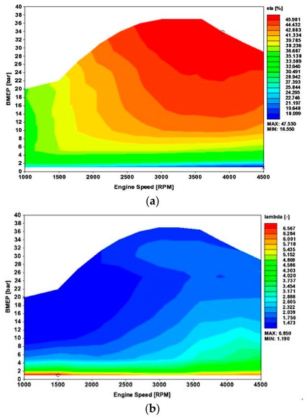
Appl. Sci. 2020, 10, 1296                                                                            2 of 28

the lean-burn operation, with combustion occurring with excess air [23]. The reduction of both PM
and NOx is achieved by after-treatment. As the after-treatment is imperfect, the diesel combustion
strategies are dictated by the best trade-off between PM and NOx emissions.
      The use of a fuel with reduced carbon content, that is also gas in normal conditions, such as the
NG, has major advantages in both CO2 and engine-out PM emissions. Even if injected liquid, the NG
rapidly vaporizes and quickly mixes with the air. The PM emissions are usually negligible. Not having
the constraint of the best PM-NOx trade-off to design the injection profile, the injection profile can
be shaped to achieve reduced NOx production. Thus, NG indirectly also permits to reduce the NOx
engine-out emissions. NG (CH4 ) has a smaller carbon-to-hydrogen ratio vs. the diesel (C13.5 H23.6 )
also featuring a higher lower heating value. Less CO2 is emitted to produce the same output of the
diesel with the same η. As NG is also gas in normal conditions, this practically reduces to zero the PM
emissions. In the dual-fuel (2F) operation, the only PM originates from the pilot diesel.
      As NG is a low cetane but a high octane number fuel, it is difficult to use alone in a CI ICE The
issue is solved by using the 2F diesel-NG design with the diesel-injection-ignition [24,25]. A small
amount of the DI diesel fuel ignites mixed with air within the cylinder. The NG that is injected prior,
or after the diesel, then burns premixed, i.e. diffusion. The first phase of combustion translates into a
rapid pressure build-up. The rate of combustion of the second phase is determined by the injection
rate of the NG.
      One issue with fuels that are gases under normal conditions is the specific volume, as the density of
the gas under normal conditions is much lower than that of liquid diesel or gasoline fuels. This creates
problems for the injection system. A fuel such as compressed natural gas (CNG) needs injectors of
much larger cross-sectional areas than diesel fuel. This makes difficult the fast actuation of the injector,
thus preventing multiple injection capabilities and shaping of the injection profile. There is also a
problem with the storage on board. The volume of CNG needed for a given amount of energy is much
larger than for diesel. The issue of CNG is partially addressed by the storage and the injection of the
NG as a cryogenic fluid. LNG gives opportunities but also challenges. LNG has a much larger density
than CNG, even if less than the diesel. However, it must be kept at very low temperatures of about
113 K.
      The two opportunities presently available, compressed NG or CNG, with the NG stored gas at
(relatively) high pressure (HP), and liquefied NG or LNG, with the NG, stored liquid at extremely low
(cryogenic) temperature, target different vehicles for different applications. The first is more suitable
for passenger cars, and vehicles that spend the most part of the time parked. The second better fits the
needs of long haul HDT, which are mostly traveling long distances.
      Current turbocharged (TC) DI diesel ICEs have achieved significant power densities and high η.
Brake mean effective pressures (BMEP) are in excess of 30 bar at about 4500 rpm maximum speed.
Peak power η is in excess of 46–47%, and peak efficiency η is about 50%. Additionally, these ICEs
deliver high η over the most part of the load range [26–29]. Same (or even better) performances are
possible with 2F operation diesel-LNG.
      Properties of diesel and LNG are given in Table 1 (data are from [30–33]). While CNG is stored in
the vehicle in HP tanks 200 to 250 bar, LNG is NG that is liquefied by cooling to 113.15 K at atmospheric
pressure for an about 2.5 larger volumetric density. Injection pressure here considered, achieved
through an LNG injection pump, is 300 bar. Being the LNG a real-world fluid, the actual formula
is different from pure methane CH4 , as the percentage of ethane C2 H6 is everything but negligible.
The formula C13.5 H23.6 proposed for the diesel is not representative of the actual composition, which is
quite variable across the markets, the seasons, and the suppliers.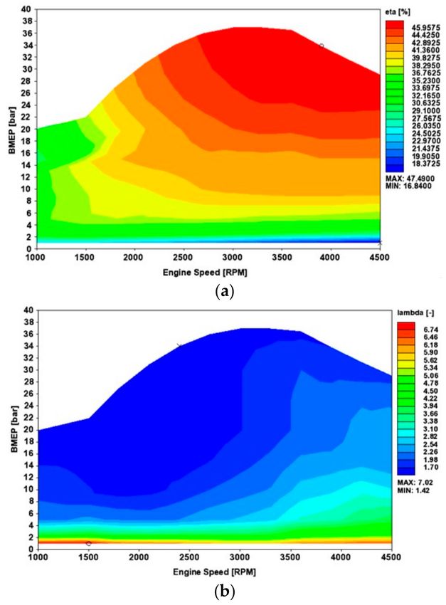
Appl. Sci. 2020, 10, 1296                                                                                   3 of 28

      Table 1. Reference properties of LNG and diesel fuel. Differences exist between sources, also depending
      on the actual composition of the real fluid.

                                                            Diesel                  LNG
                            Chemical Formula              C13.5 H23.6               CH4
                       Carbon Atoms per Molecule             13.5                      1
                      Hydrogen Atoms per Molecule            23.6                      4
                            Molecular Weight                 186                      16
                     Physical State at 15 ◦ C and 1 bar    Liquid                    Gas
                          Injection pressure bar             2850                    300
                         Injection temperature K             298                     113
                              Density kg/m3                  837                    443.5
                                LHV, MJ/kg                  43.25                   50.00
                               HHV, MJ/kg                   45.60                   55.00
                    Latent Heat of Vaporization, MJ/kg       0.25                    0.50
                         Critical Temperature, K            569.4                   190.4
                           Critical Pressure, bar            24.6                     46
                              Physical State               Liquid              Cryogenic Liquid
                             Cetane Number                  40–55                   N/A
                             Octane Number                   N/A                    120+
                               Flash Point K                 347                     425
                      Auto-ignition Temperature K            589                     813
                   Lower Flammability limit, volume %          1                      5.3
                   Higher Flammability limit, volume %         6                      15

     Figure 1 presents a sketch of a conventional diesel (C13 H28 ) and a conventional LNG (CH4 )
molecule. Figure 2 then presents the isothermal and isobaric density of methane at 114 K and 300 bars.
When injected within the combustion chamber, the pressure reduces and the temperature increases.
The temperature increases quickly, translating in the vaporization of the LNG.

                                         Figure 1. Diesel and LNG molecules.

     Replacing diesel by LNG can help reduce CO2 and PM engine-out emissions from diesel ICEs,
with the opportunity of also improving the NOx engine-out emissions, as the injection and heat release
curves of an LNG ICE are not constrained by the PM-NOx engine-out emission trade-off of a diesel
ICE. LNG-diesel 2F ICEs maintain the higher fuel conversion efficiency η of diesel ICEs while replacing
a significant amount of diesel with LNG.
     The 2F diesel-LNG ICE may perform better than the diesel, being the LNG much easier to vaporize,
and to mix with air, allowing relative fuel-to-air ratios ϕ = 1/λ larger than the diesel. A diesel ICE can
be easily converted to an LNG-diesel 2F ICE, which makes the technology suitable for both new ICE
manufacturing and retrofitting existing diesel ICEs.
Appl. Sci. 2020, 10, 1296                                                                                    4 of 28

      Figure 2. (a) Isobaric density of methane at 300 bars of pressure. (b) The isothermal density of methane
      at 114 K of temperature. Data from [30].

      Some known issues of the 2F diesel-LNG ICEs developed so far are the limited replacement ratio,
efficiency deterioration, and the incomplete combustion of the LNG at low load conditions [34,35].
These issues may be addressed by assisted turbocharging, where the speed of the turbocharger can be
altered from the balanced operation of turbine and compressor, by fitting an electric motor-generator
to the turbocharger shaft (the FIA F1 style MGU-H, [26,36]) or connecting the turbocharger shaft to the
crankshaft via gear and a variable speed transmission, that is an evolution of the Torotrak V-Charge
supercharger, [37–39], for super turbocharging, [26,27,40], and obviously with a better injection system.
The assisted turbocharger control, coupled to the air-cooling control, allows to produce the most
suitable values of pressure and temperature at intake valve closure (IVC) for every speed and load of the
steady-state map, and additionally address the transient issues, for both acceleration and deceleration.
      Further improvements of the injection system are however fundamental. The success of the
latest diesel ICEs in terms of power density and η stems from the opportunity to inject the diesel
at extremely elevated pressures (2850 bar already in 2014) with high flow rate, high atomization,
and using multiple injection events, precisely defined in time thanks to the fast actuation, often piezo
rather than solenoid. The shaping of the injection translates in the shaping of the heat release curve,
and thus the construction of a pressure curve where the rate of pressure build-up, the peak pressure,
Appl. Sci. 2020, 10, 1296                                                                               5 of 28

and the crank-angle location of the peak pressure, can be finely tuned. The shape of the temperature
curve is also relevant, for example for NOx production within the cylinder. Similar capabilities are
impossible with present CNG or LNG injectors that do not have the same speeds of actuation and
mass flow rates of the latest diesel injectors.
     The purpose of this paper is to focus, after a review of recent diesel and diesel-LNG achievements,
and the latest diesel and diesel-LNG developments, on the improvements needed in CI LNG-diesel 2F
ICEs using pre and post injections of LNG coupled to the diesel pre/pilot injections. The manuscript
covers fundamental injection and combustion strategies, with advanced control of turbocharging and air
cooling, as well as injection shaping for both fuels, diesel, and LNG, to achieve better-than-diesel-only η
and power density within constraints of pressure build-up rate, peak pressure, and peak temperature.
     The work will propose first a review of the literature and the market data of diesel-LNG ICEs.
Then, ICE performance simulations are proposed to provide the first proof of concept of the novel
technologies being developed for these ICEs.

2. Results

2.1. 2F Diesel-LNG ICEs R&D
     The principles of multijet diesel ICE operation are well-known [41]. In the past, diesel ICEs were
designed by using a single injection by a mechanical injector [42]. This single injection produced
significant issues despite the fact the flow rate was relatively small, as the premixed combustion after the
ignition delay produced a relatively large pressure build-up (dp/dθ, with p pressure, and θ crank angle),
as well as maximum cylinder pressure, with the subsequent diffusion combustion often insufficient to
allow a proper shape of the heat release curve and thus of the pressure curve. pre-chamber diesel ICEs
were often preferred to DI diesel ICEs due to the injection and combustion issues.
     Things drastically improved when FIAT replaced this single diesel fuel injection of the past,
with the Unijet [41]. In this case, the fuel injection was separated by introducing a pilot injection before
the main injection. A common rail was delivering at relatively HP the pressurized diesel to the different
injectors, and solenoid actuation was allowing relatively fast (for the times) speeds of actuation.
     The Unijet innovation was so successful that the share of diesel passenger cars in Europe increased
from about 10% to more than 50%. The Unijet technology then evolved in the more recent Multijet
(and comparable products) injection system featuring multi injection strategies, where the number
of injection events has been made larger, with actuation also made much faster, injection pressures
dramatically increased, and fuel atomization drastically enhanced. The diesel ICE dramatically
improved over the last three decades, mostly because of the turbocharger and the Multijet technology.
These two key developments improved efficiency, power density while delivering less noisy operation,
fewer vibrations, within acceptable mechanical stresses due to both peak pressure and rate of pressure
build-up and reduced out emissions of smoke and nitrous oxides (NOx).
     The Unijet fuel injection system of the 1990s was using a pilot injection for noise reduction and
the main injection for torque control. The Multijet fuel injection system of the early 2000s increased
the number of injections to a total of five for more refinement and performance. With Multijet,
the injection is divided into multiple smaller injections, pilot and pre for noise reduction, to produce
suitable conditions for the main injection fuel to easily and quickly burn diffusion-controlled, one main
injection, plus after and post injections for catalyst light-off, soot reduction, and diesel particulate filter
regeneration. In 2009, the further evolved Multijet II now included up to eight injections per cycle.
     With Multijet, the injection is divided into multiple smaller injections, pilot and pre for noise
reduction, to produce suitable conditions for the main injection fuel to easily and quickly burn
diffusion-controlled, a first main injection for noise and NOx reduction to further improve the
in-cylinder conditions to accept the most part of the fuel in a second main injection, a second main
injection to further control the torque within constraints of noise and NOx, plus after and up to three
post injections for catalyst light-off, soot reduction and diesel particulate filter regeneration with
Appl. Sci. 2020, 10, 1296                                                                            6 of 28

reduced oil dilution. The injection rate shaping resulted in better combustion control allowing to also
control emissions and improve fuel efficiency and power density while limiting noise and vibrations.
      As NG needs a higher ignition temperature than diesel, the temperatures about the top dead
center (TDC) of typical diesel ICEs are not enough to allow the combustion of the NG diesel-like.
While a properly redesigned ICE could work diesel-like also with high octane number gases such as
NG or hydrogen [43,44], this may require a different control of pressures and temperatures within
the chamber, as well as wall temperatures, to properly work, and therefore significant research and
development effort may be needed. To aid with ignition, a small amount of diesel fuel is injected into
the ICE followed by the main NG injection. Westport HPDI replaces approximately 92% of the diesel
fuel (by energy) with NG.
      The Westport HPDI technology was developed for diesel and LNG to replace the main injection
of the diesel with a more environmentally friendly fuel, NG, delivered liquefied. The Westport HPDI
system for diesel and LNG is well established by decades [24,25,45,46]. It may be regarded as an
innovation relevant to transport not less than turbocharging and the Unijet for the diesel. The Westport
HPDI technology uses NG as the primary fuel along with a small amount of diesel as a pilot ignition
source, or “liquid spark plug”. The ICE uses a revolutionary injector with a dual-concentric needle
design allowing DI of small quantities of diesel and copious quantities of LNG. The LNG is injected at
the end of the compression stroke, after the diesel pilot, and it burns diffusion controlled.
      The Westport HPDI [25] is an integrated system offered for new trucks or conversion of existing
diesel trucks permitting operation with NG for reduced fuel costs, reduced CO2 emissions, reduced
soot emissions, and diesel-like performance. The Westport HPDI offers the same power, torque, engine
braking and drivability of the diesel. The Westport HPDI also allows inherently low engine-out
emissions of unburnt methane. Westport HPDI consists of a cryogenic tank, an HP LNG, HP fuel rails,
and a dual concentric needle injector. This injector allows independent delivery of small quantities of
diesel fuel for pre/pilot injections and massive quantities of NG as the main injection, both at relatively
HP, directly to the combustion chamber. The NG is injected at the end of the compression stroke
after the diesel, and it burns diffusion controlled. Further developments are being considered for this
basic concept.
      The Westport HPDI system for diesel and CNG/LNG is a technology well established over the last
three decades [45,46]. This technology has been further evolved from a simple main injection of NG
following the pilot/pre diesel injection, to more complex strategies that include premixed and diffusion
combustion of the NG, as it was suggested in [47]. Traditional HPDI of LNG in HDT ICEs allows an
NG ICE to maintain diesel-like performance while using to a major extent the fuel energy of the NG.
The small diesel pilot injection accounts for 5–10% of the fuel energy. It is used to ignite the DI LNG.
The NG burns in a mixing-controlled, or diffusion, combustion mode, depending on being injected
prior or after the pilot diesel.
      Increased pressure, 600-bar 2F injectors for the LNG and the diesel are reported in [48]. The LNG
combustion event is limited by the injection pressure. The injection pressure dictates the rate of
mixing, and thus the combustion rate. By increasing the injection pressure from the traditional
300-bar to 600-bar, significant efficiency improvements and PM reductions are achieved at high loads,
and especially at higher speeds. As a collateral effect, because pressure build-up and combustion rate
are linked together, increases in combustion noise and harshness are drawbacks of the larger injection
rates and the faster combustion allowed by the higher injection pressure. As mitigation strategies,
a reduction of the diameter of the LNG nozzle holes may help to control the fuel injection rate and
the combustion rate. Higher pressures driven faster combustion improves efficiency, with benefits of
about 3%. Additionally, PM reductions are of the order of 40–60%.
      Reference [49] used a prototype fuel injector nozzle. Seven individual equally spaced gas injection
holes are replaced by seven pairs of closely-aligned holes (“paired-hole nozzle” in [49]). The paired
hole nozzle is intended to reduce PM formation by increasing the air entrainment due to the interaction
with the jet. Opposite to the expectations, CO and PM emissions increased. They were three to 10
Appl. Sci. 2020, 10, 1296                                                                             7 of 28

times higher when using the paired hole nozzles. Despite other significant differences, the relative
change in emissions in response to the parametric changes was similar for a single hole and paired
hole nozzles. The paired hole nozzle produced larger soot aggregates as well as larger numbers of
particles. There were no significant changes in the soot primary particle size.
      Reference [50] supplies an overview of the improvements in the Westport HPDI 2.0, as well as
performance and emissions results. The new generation HPDI delivers significant advantages vs. the
baseline diesel in terms of performance and emissions. Further improvements vs. the first generation
HPDI are also evidenced. The potential and challenges of adopting higher injection pressures are
also highlighted.
      Reference [51] uses the Westport HPDI ICE to study both diffusion-controlled and partially
premixed combustion strategies. The partially premixed combustion is called DI2 . The DI2 combustion
strategy is promising. It improves ICE efficiency by two efficiency points compared to the traditional
diffusion combustion.
      The DI2 is also studied in [52], where a partially premixed fuel-air charge is obtained by injecting
the NG during the compression stroke. This injection is then followed by the diesel-injection-ignition.
This combustion strategy improves the thermal and combustion efficiencies over the traditional
fumigated 2F ICEs. This is by no way a surprise. DI2 also supplies significant improvements in
thermal efficiency over the baseline diffusion combustion strategy of HPDI. Injecting some NG prior to
the diesel ignition injection thus sometimes provides better results than injecting the NG after diesel
ignition injection. The opportunity depends on the specific speed and loads operating point.
      References [53,54] study the effect of injection strategies on emissions from an HPDI ICE. The two
works report the two parts of the same experience. Part I investigates the effect of late post-injection
(LPI). Part II investigates slightly premixed combustion (SPC). The criteria for comparison are emissions
and performance. In the SPC operation, the diesel injection is delayed, allowing more premixing of the
NG before ignition. SPC operation at high load reduces 90% of the PM with a 2% improvement in
fuel efficiency while delivering the almost same level of NOx. Drawbacks of SPC are cycle-to-cycle
variation and excessive pressure rate of rising. PM does not increase for SPC with higher EGR level,
higher global oxygen-based equivalence ratio (EQR) or higher pilot mass, which normally increases
PM in mixing-controlled HPDI combustion. In the traditional diffusion combustion, there is too much
fuel-rich stoichiometry at the time the NG is ignited. With SPC, the mass of fuel in the rich zone is
less than 10% of the fuel in the rich zone of the mixing-controlled combustion. The potential for soot
formation is thus drastically reduced. The morphology of particles produced by SPC is similar to the
morphology of particles produced from the conventional diffusion combustion. The size and number
concentration are however reduced.
      The post-injection of [53,54] typically accounts for 10–25% of the total fuel mass. It occurs after the
main combustion event. LPI produces significant PM reductions. There are only minor other effects on
other pollutant emissions and performance. The morphology of particles produced by LPI is similar
to the morphology of particles produced from the conventional diffusion combustion. The size and
number concentration are however reduced. The main PM reduction of LPI originates from the smaller
amount of fuel in the first injection, which is leading to a lower PM formation in the main combustion
event. The second injection makes an insignificant contribution to the total PM.
      Significant advances have been recently achieved in CI hydrocarbon ICEs for racing car applications.
Novel 2F diesel-LNG CI ICEs may certainly receive help from these experiences. For what concerns CI
ICEs working with diesel fuel, the ICE of the Audi R18 TDI Le Mans (2016 specs) is certainly worth
mentioning. In 2016, Audi stepped up to the 6 MJ hybrid energy and adopted a lithium-ion battery in
their diesel-powered R18 for Le Mans. The electric drive system on the front axle had a recharging
power of 350 kW. However, the discharging power was less. At Le Mans, the electric drive system only
supplied 300 kW during accelerations.
      The maximum power delivered by the ICE was limited by the fuel flow rate. For a 6 MJ hybrid
energy, the maximum fuel flow rate was 71.4 kg/h. This translated, for a 43.4 MJ/kg Lower Heating
Appl. Sci. 2020, 10, 1296                                                                        8 of 28

Value (LHV) of a nearly pump diesel fuel, in a fuel flow power of 860.8 kW, or 1154.3 HP. For η = 0.45
at a speed of about 4500 rpm, that is a technological limit of diesel combustion, (this is the peak η
at a lower engine speed of the best in class production high-speed diesel ICEs for a passenger car),
the maximum engine power at the crankshaft was 387.4 kW or 519.4 HP. The ICE was working full load
lean diffusion with an air-to-fuel equivalent ratio of about λ = 1.45. Coupled telemetry and lap time
simulations [55] suggest for the 3.7 L V6 TDI ICE powering the rear axle of the R18 a maximum output
of 378 kW or 514 HP during 24h-race conditions. The computed maximum torque was about 850 Nm
over the speed range of 3250 to 4250 rpm where the engine typically works over a lap of Le Mans [55].
Figure 3 presents the reconstructed performance curves of a 2015 WEC LMP1-H TDI ICE. In (a) is
the maximum BMEP vs. speed, and in (b) the fuel conversion efficiency vs. speed. These curves are
reconstructed from the telemetry data of vehicle and engine speed vs. time, plus the maximum torque
and power and the fuel flow rate limits as described in [55].

      Figure 3. Reconstructed performance curves of a 2015 WEC LMP1-H TDI ICE. (a) BMEP vs. speed,
      (b) fuel conversion efficiency vs. speed.

     Figure 4 presents the performance curves of a modified Westport 15L HPDI diesel-LNG ICE
and the baseline Cummins L15 ISX 450 ICE. Data digitized from images previously published by
www.westport.com. This HDT ICE only works up to 2000 rpm. Over the speed range 1100 to 2000 rpm,
the full-load performance of the diesel is perfectly reproduced by the diesel-NG conversion. IN terms
of torque, the diesel-only has a small advantage at 1100 rpm, and a small disadvantage at 1600 rpm.
At 1900 and 2000 rpm, the diesel-NG ICE has some consistent advantage. As reported by Westport,
also the fuel conversion efficiencies were comparable, while the PM emissions were dramatically
reduced, as reduced where the CO2 emissions.
Appl. Sci. 2020, 10, 1296                                                                           9 of 28

      Figure 4. Performance curves of a Westport 15L HPDI diesel-LNG ICE and the Cummins L15 ISX 450
      ICE. Data digitized from images previously published by www.westport.com.

      Being the combustion of the diesel limited by the time needed by the fuel to evaporate, mix with
the air and auto-ignite, the duration of the combustion event is very well known to become prohibitive
above the 4500 rpm, reason why also racing diesel ICEs have same, or marginally higher, maximum
engine speed of passenger car diesel ICEs, and therefore a small power density compared to gasoline.
Slightly larger efficiencies, than the peak power efficiency, are obtained at peak torque. Additionally,
by reducing the load by the quantity of fuel injected, the efficiency may be further improved in the
medium to high load range about the peak torque speed.
      DI is superior to port fuel injection (PFI) of LNG or CNG for obvious reasons. The displacement
effect, i.e., the volume of air through the intake valves reduced by the volume of the NG, that is minimal
with LNG, as the vaporization of the LNG then reduces the temperature of the intake air and thus
increases its density, is not the major issue. In the high boost, high compression ratio environment
typical of the latest TDI, even a high-octane number fuel such as NG may experience knock under some
circumstances. DI during the compression stroke of the NG, even to burn premixed, leaves less time
to knock to occur before the diesel-injection-ignition. Furthermore, every homogeneous combustion
produces larger heat losses to the wall and incomplete combustion for flame quenching. Hence, best it
to inject the NG to burn premixed during the compression stroke at the center of the combustion
chamber, to produce a central lean stratified mixture, surrounded by a cushion of air. Opposite to the
diesel, the NG is a much simpler hydrocarbon, and even if LNG, it takes less to vaporize and mix with
the air than the diesel. Injection of the NG to burn diffusion may only be direct. This occurs after the
diesel-injection-ignition has produced suitable conditions within the chamber for the NG to quickly
vaporize (if LNG), mix with air, and burn.
      The Westport HPDI 2F diesel-LNG injector does not offer the same performance for the diesel
of a latest-generation diesel-only injector, in both flow rate, speed of actuation, and atomization.
A dedicated LNG injector may also supply better performances than the LNG-diesel injector dual fuel.
2F diesel-hydrogen CI ICEs featuring this possibility were studied for example in [56,57]). In these
applications, two DI injectors were used per cylinder, one for the diesel and one for the hydrogen.
A diesel ICE converted to a 2F diesel-hydrogen ICE following this approach could have delivered full
load efficiencies up to 40–45% and reduced penalties in efficiencies reducing the load.
      The secrets of the turbocharged TDI CI Diesel ICEs performances are the high compression
ratio and boost, the lean bulk combustion mostly diffusion-controlled, in addition to the better use
of the exhaust energy. A latest production common-rail diesel ICE could be changed, replacing the
diesel injector by a double injector as those proposed by Westport [45,46] for CNG/LNG, or also
by using two injectors, to supply same or better performances of the diesel, [57]. The use of two
dedicated, rather than one 2F injector may have advantages and disadvantages. It is more complex and
difficult to propose in conversions of existing ICEs. It may deliver much more flexibility in injection
Appl. Sci. 2020, 10, 1296                                                                             10 of 28

shaping. The 2F operation is typically characterized by pilot/pre-diesel injections, about the same
of diesel-only operation, followed by the main LNG injection. The power density is increased by
increasing the fuel-to-air ratio (i.e., reducing the λ) with LNG. The 2F diesel-LNG ICE may have slightly
better-than-diesel η and higher-than-diesel power outputs, same as the diesel-hydrogen ICE of [56],
as the NG vaporizes and mixes with air quicker than the diesel, providing about the same mass flow
rate is kept unchanged.
      As discussed later, the LNG has not to be all injected after the diesel-injection-ignition. It may also
be injected before or at the same time as the diesel. Thus, it may burn partially premixed and partially
diffusion, and not the only diffusion. The LNG injected before the diesel increases the heat released
during the premixed combustion, also reducing the amount of the diesel needed to produce suitable
conditions for the LNG injected later to burn diffusion controlled.
      The CI 2F diesel-injection-ignition ICE can be run with different modes of combustion by simply
modulating the amount of LNG injected before and after the diesel-injection-ignition. More or less
“controlled” HCCI modes of combustion are also possible, with the diesel-injection-ignition occurring
prior to the expected start of the HCCI auto-ignition, to supply stability to the otherwise unstable HCCI
system [58]. It is, however, to be pointed out that HCCI has no advantage vs. the bulk combustion in
the center of the combustion chamber surrounded by a cushion of air, as the homogeneous combustion
always suffers from larger heat losses at the walls and incomplete combustion for quenching of the
flame. From a pure pressure build-up perspective, HCCI also does not produce a peak pressure during
the expansion stroke, being HCCI ICEs statistically limited to deliver peak pressure exactly at top
dead center. Hence, the LNG must be injected at the center of the chamber and burned by the diesel
injection before filling homogeneously all the chamber. This is possible with late, fast, high flow rate,
injections of the LNG.
      Also, Westport HPDI is evolving towards more complex injection and combustion modes, where
there is the opportunity of premixed and diffusion NG combustion but constrained using their patented
large 2F injector. The major advantages of HPDI are the ability to do the injection of the diesel
and the NG with a single injector. The major disadvantage of this approach, vs. the use of two
dedicated injectors, one for the diesel and one for the NG, is the inability to achieve for the diesel same
actuation times, injection pressure, atomization, and flow rates, of the latest single fuel diesel injectors,
and certainly longer actuation times, smaller flow rates, and more constrained jet shapes, for the LNG,
vs. a dedicated single fuel LNG injector, however presently unavailable off the shelf.
      It is the rate of injection that limits the diffusion combustion of the LNG. It is the actuation time
and the rate of injection, to a lesser extent, that limit the amount of LNG that can be introduced to burn
premixed. The injection profile and the heat release profile are linked to each other. Apart from the 2F
diesel LNG DI injector by Westport, which is a high-tech, off-the-shelf product, other manufacturers
have not developed competitive products in recent years. Hoerbiger developed a single fuel DI injector
for hydrogen, a much more demanding than NG fuel that is at normal conditions, in the early 2000s
during the attempts by BMW to produce a hydrogen car. However, the development of this injector
ended with the end of the BMW project [44]. Hoerbiger designed HP injectors for DI of hydrogen into
the combustion chamber with pressures of up to 300-bar. These injectors were tested and calibrated at
the Hydrogen Center Austria, which also supplied the hydrogen infrastructure for the project.
      To conclude, the latest development of 2F diesel LNG ICEs is to directly inject both fuels, in a
chamber with suitable pressure and temperature, as resulting from advanced turbocharging, shaping
the heat release rate curve to produce a pressure profile where:

-     Pressure must rise fast about TDC during the premixed combustion phase, but within limits for
      what concerns the dp/dθ and the TDC maximum pressure.
-     Pressure must continue to grow during the early expansion phase, to produce a peak pressure
      about 13–14 degrees crank angle after TDC. The peak pressure must be within acceptable limits.
      The fuel flow rate must be large enough during this phase.
Appl. Sci. 2020, 10, 1296 11 of 28
- As the work during compression is negative, and only the work during expansion is positive,
the amount of heat released during the premixed and diffusion phases must be carefully controlled
to maximize the η within the constraints.
- An adequate fuel flow rate from the LNG DI injector, as well as the rate of actuation, are crucial to
achieving the above goals.
Further developments of 2F diesel LNG ICEs strongly depend on the ability to produce dedicated
injectors allowing high flow rates, and fast actuation, with multiple injection capabilities, i.e.,
pretty much the same demand for the latest single fuel diesel injectors but for the reduced density
cryogenic LNG.
It must be added that the use of two injectors per cylinder is not certainly a problem of packaging,
as diesel ICEs have easily accommodated a DI and a glow plug for many years until the further
progress of DI has made the glow plug redundant, and gasoline DI, jet or spark positive ignition (PI)
ICEs adopt one DI injector plus the jet ignition (JI) device or the spark plug (SI) with much larger intake
and exhaust valves than the CI diesel ICEs.
2.2. Computational Proof of Concept of Novel Diesel-LNG ICE Designs
ICE performance simulations are performed by using state of the art computer codes of the
operation of turbocharged and super-turbocharged diesel and diesel-LNG ICEs. Description of the
modeling strategy and past application to dual-fuel diesel-alternative fuel engines are presented
in [59–65]. Simulations have been performed for an engine fueled in one case with diesel only, and one
case with diesel and LNG. Pollutant emissions are disregarded. Figure 5 presents a sketch of a V6 TDI
CAE model, that allows simulation of the operation of turbocharged, electrically aided turbocharged
and super-turbocharged ICEs, for CI operation.
Figure 5. Sketch of a V6 TDI model, with compressor and turbine shafts connected to the crankshaft.Appl. Sci. 2020, 10, 1296 12 of 28
This model may be used to simulate super-turbocharging, with gears and a continuously variable
transmission (CVT) toroidal mechanism connecting crankshaft and turbocharger shaft, as well as a
motor-generator unit connected to the turbocharger shaft of electrically assisted turbocharging. In this
case, post-processing is needed to depurate the crankshaft power output of the power from/to the
turbocharger shaft. Through the motor/generator unit (MGU-H), this extra power is delivered or
extracted from the traction battery, also used by the kinetic motor generator unit (MGU-K) delivering
power to the wheels or recovering the braking energy.
Figure 6 is the sketch of the classic turbocharged solution. Computer-Aided Engineering (CAE)
ICE performance simulations are very well known and very well established tools, with many
different suppliers as well as users of products providing very close results in between them and with
experiments. Modelling of V6 TDI engines is discussed in [65–67].
Figure 6. Sketch of a V6 TDI model, with a traditional turbocharger.
The ICE considered is a 3.7-L TDI V6, of bore 92.5 mm, stroke 90 mm, connecting rod length
180 mm, compression ratio 17.5. The V6 had a V-angle of 120 degrees. This ICE model was developed
as part of a study for the ICE of a Fédération Internationale de l0 Automobile (FIA) world endurance
championship Le Mans Prototype class1 hybrid car. Target performances were those expected from
the Audi LMP1-H.
With electrically assisted turbocharging, the total power at the crankshaft must be depurated
during post-processing of the difference between the power from the turbine and the power to the
compressor. The extra power needed at the turbocharger is obtained from the battery, as the extra
power produced by the turbocharged is delivered to the battery, through the electric motor/generator
unit. In mechanically assisted turbochargers, the positive difference between the power from the
turbine and the power to the compressor is multiplied by the mechanical transmission efficiency.
The negative difference between the power from the turbine and the power to the compressor is
divided by the mechanical transmission efficiency. In the case of a traditional, balanced turbocharger,Appl. Sci. 2020, 10, 1296 13 of 28
compressor and turbines are linked to each other through a shaft and disconnected from the crankshaft.
While the efficiency of the mechanical connection to the crankshaft is relevant [40], it must be pointed
out as this efficiency only weighs on the difference between the turbine and compressor works.
Combustion is modeled through diesel Wiebe functions. Combustion is not predictive but
correlative. It is modeled by using the same DI diesel Wiebe functions for the super turbocharged and
turbocharged versions, diesel only and diesel-LNG. This model permits to define the Ignition Delay,
that is the delay in crank-angle degrees between the start of injection and the start of combustion,
the Premixed Fraction, that is the fraction of fuel that mixes before the start of combustion and burns
in the premix portion of the Wiebe function, the Tail Fraction, that is the fraction of fuel that burns
beyond the main diffusion burn, the Premixed Duration, that is the duration in crank-angle degrees
of the premixed burn, the Main Duration, that is the duration in crank-angle degrees of the main
diffusion burn. The main duration excludes the first and the last parts of the area under the main burn
curve, the Tail Duration, that is the duration in crank-angle degrees of the tail burn curve, and finally
the Premixed, Main and Tail Exponents of the Wiebe curves for the premixed burn, the main burn,
and the tail burn. These parameters are empirical values obtained from measurements of similar ICEs
tabulated vs. BMEP and speed.
The definition of the combustion model is coupled to the definition of the multi-event injection
profile, which includes pre/pilot and main injections. This model is set up for the diesel-only operation.
In the case of the 2F diesel-LNG, it is simply assumed that the diesel pre/pilot amounts are the same as
the diesel only, and only the main LNG replaces the main diesel. As only one fuel is considered in
the model, the pre/pilot diesel injection is replaced by an LNG injection of equivalent energy content,
the same as the main diesel injection. As the controller adjusts the total mass of fuel injected to match
the requested BMEP at every speed, there are minor differences between the energy inputs of the diesel
and the diesel-LNG models for the same BMEP and speed operating point.
While the accuracy may certainly be improved by adopting a model accounting for chemical
kinetics and multiple species, this approach not only needs more computational effort, it also needs
substantial experimental support to tune and confirm the model. Not considered here is the possibility
in the real ICE to inject some LNG prior or contemporary to the diesel pre/pilot, which may increase
the premixed combustion, and produce conditions within the chamber more favorable for the LNG
main injection fuel to burn diffusion controlled.
Finally, in computing the LNG replacement fuel, it is simply assumed that the amount of the
diesel fuel injected during the pilot/pre-injections is about constant in mass, and thus a linear function
of the engine speed. Experimentally, this assumption is correct at medium-to-high loads and high
speeds, while in the low speed and low loads region the amount the diesel fuel introduced with the
pilot/pre-injections may be larger.
Figures 7 and 8 present the computed η and λ maps of the super turbocharged and turbocharged
diesel ICE, while Figures 9 and 10 present the η, λ, and LNG energy/total fuel energy maps of the super
turbocharged and turbocharged diesel-LNG ICE.
The advantages of the super turbocharger (or electrically assisted turbocharger) are clear at low
speeds, where higher BMEP is made possible, and at high speeds high loads, where the extra energy at
the turbine is not waste gated but recovered. Not included in the simulations, that are only steady-state,
are the further advantages during a transient, both accelerations, as the turbo-lag is completely canceled
supplying the extra energy needed by the compressor, and during decelerations, where the extra
energy delivered by the turbine is also recovered.
Concerning diesel only, the diesel-LNG ICEs provide slightly better η, both in the
super-turbocharger and turbocharger versions, running with smaller λ at the higher loads.
The replacement LNG energy may be as high as 98% of the total fuel energy, at the higher loads and
speeds. It is well above 90% up to 8 bar BMEP. The LNG energy reduces with the load and the speed.
The values proposed in Figures 9 and 10 are certainly optimistic for the low load and low-speed area,
which was not of interest in the development of the racing ICE.Appl. Sci. 2020, 10, 1296 14 of 28
Figure 7. Maps of η (a) and λ (b) of the super turbocharged diesel ICE.Appl. Sci. 2020, 10, 1296 15 of 28
Figure 8. Maps of η (a) and λ (b) of the turbocharged diesel ICE.Appl. Sci. 2020, 10, 1296 16 of 28
Figure 9. Maps of η (a), λ (b) and LNG energy/total fuel energy (c) of the super turbocharged
diesel-LNG ICE.Appl. Sci. 2020, 10, 1296 17 of 28
Figure 10. Maps of η (a), λ (b) and LNG energy/total fuel energy (c) of the turbocharged diesel-LNG ICE.Appl. Sci. 2020, 10, 1296 18 of 28
3. Discussion
3.1. Substitutional LNG
As shown by [68] studying a 2F diesel-LPG 1.6-L 4-cylinder ICE derived from a passenger car ICE,
the amount of diesel needed in these operating conditions may be larger. As the baseline ICE model of
the present study was developed targeting the high speed and load operation as customary in racing
ICE applications, the low-speed low load definition of the pre/post injections was not of particular
interest. The reference experimental definition of the pre/pilot mass flow rate of the small diesel 1.6 L
is proposed in Figure 11.
Figure 11. Reference mass flow rate of diesel pre/pilot for a small 1.6-L diesel ICE for passenger cars.
(a) fuel flow rate. (b) the ratio of pre/pilot to pre/pilot plus main flow rates.Appl. Sci. 2020, 10, 1296 19 of 28
Especially in the low-speed operating points, where turbocharging does not produce enough
boost, the amount of diesel needed for the pre/pilot injections may be large, also 50% of the total mass
injected in the worse cases. With super turbocharging or electrically assisted turbocharging, the issue
is less relevant. With more complex strategies of injection of the LNG, suitable conditions for the main
injection of the LNG to progress diffusion-controlled may also be obtained by injecting a small amount
of LNG prior or contemporary with the diesel-injection-ignition. This option may permit to drastically
reduce the diesel needed. This is a major advantage vs. the Westport HPDI.
Where convenient, the amount of the LNG injected before the diesel-injection-ignition may be
increased to almost any value, thus producing a very fast combustion, close to an HCCI combustion,
but with the advantage of reduced heat losses, as the LNG premixed with air may be concentrated
at the center of the chamber where it is ignited by the diesel-injection-ignition, with a cushion of air
surrounding this area and limiting the heat transfer to the walls.
In addition to assisted turbocharging, air cooling, and injection shaping, exhaust gas recirculation
(EGR) is a control option that is effective to reduce the NOx engine-out emissions [52,69,70]. The EGR
reduces the NOx lowering the oxygen concentration in the combustion chamber, as well as absorbing
heat. As the present work has only focused on performances and not emissions, EGR has not
been considered.
It must be added that the injection of liquid CH4 after the diesel under certain conditions may
quench the burning of a too-small quantity of diesel that consumes at relatively low pressure and
temperature. Similarly, the injection of liquid CH4 before the diesel if excessive for the pressure
and temperature of air and residuals in the chamber can also make difficult the autoignition of
the diesel. While this is unlikely to occur in the conditions here examined of a high boost high
compression ratio ICE, these opportunities are certainly worth further studies preferably through
experimental approaches.
The proposed performances of the 2F diesel-LNG CI ICEs may be further improved. As shown
in [65], a more aggressively designed ICE, with higher boost obtained by a larger mechanically assisted
turbocharger, larger compression ratio, and fuel-to-air ratio slightly less lean of stoichiometry, may have
larger BMEP and power density values (up to 30% larger), albeit without any significant improvement
of efficiencies.
The diesel ICE model was developed in 2013 and 2014 for FIA WEC applications. The injector was
a 2850-bar diesel DI injector allowing fast actuation and high flow rates and atomization. The proposed
2F diesel-LNG needs of a proper LNG injector allowing about the same of the diesel actuation times
and energy flow rates. The LNG has a drastically reduced density compared to the diesel, but a slightly
larger lower heating value. To help the design of the requested DI LNG injector, the LNG vaporizes
and mixes with air much quicker than the diesel. The density penalty is, however, a major issue, as the
larger cross-sectional areas needed to accommodate a much larger volumetric flow rate with the LNG
translate in a larger and heavier design making more problematic fast actuation. The LNG injector
supposed to be used in this paper is not available off-the-shelf, but it may be certainly produced with
today’s technological capabilities.
Starting from the experience of Prof. Hill in the 1980s and early 1990s, Westport has built a
considerable strength in converting HDT to LNG and diesel, by using their HPDI injectors. Their ICEs
have been tested on dynos by them, and by the many Original Equipment Manufacturers (OEM) who
purchased from them the HPDI conversion. There are many thousands of HDT trucks adopting this
technology that has been circulating for many years on the road, with good performances confirmed
by the truck drivers, the hardest reviewers to convince about ICE development. The Westport HPDI
conversion is very well known to produce the same of original diesel steady and transient performances,
plus the benefits of using LNG for the economy, CO2 and PM, by using a pilot diesel and the main
LNG injection.Appl. Sci. 2020, 10, 1296 20 of 28
The Westport HPDI injector is a single injector for two fuels that is very large and heavy, and it
is slow to actuate. Modern diesel injectors permit better injection strategies for more opportunities
to shape the heat release rate curve at any speed and load. The injection strategy for the diesel and
the LNG can be improved through the use of two dedicated DI injectors, one for the diesel, and one
for the LNG. The hard fact that LNG plus diesel 2F works have not to be proven once more in any
paper, and thus the proposed results are by no mean not trustworthy as they lack a specific validation.
Westport and their customers, either OEM and truck drivers, did already. It is 30 years that the Westport
HPDI is a successful product.
The novelty of the paper is the use of two dedicated injectors, rather than one single injector for
the diesel and the LNG, which is the main feature of the Westport HPDI, moving from a validated
diesel-only ICE model. Also, Westport is moving towards mixed modes of combustion, with premixed
and diffusion combustion of the LNG, that is injected prior or after the diesel-injection-ignition, as it is
also shown in their latest SAE papers. However, they are still constrained by the use of a single fuel
injector for both fuels.
The proposed two injectors, specifically developed, permit a much better shaping of the heat
release rate curve, as explained in the manuscript, thanks to the higher flow rates, the better atomization,
and the faster actuation. These improvements are logical consequences of the specific design for one
fuel only, and the higher pressures and smaller nozzle areas.
The results proposed are quite logical, perfectly aligned with what has been shown by the Westport
experience. Thus, the proposed results are backed by the Westport experience, good engineering logic,
and simulations with computer codes that have widespread use within the OEM, where changes such
as the fuel are easily accomplished with generally satisfactory results.
Regarding the injection pressure of the LNG injector, this pressure must be much larger than the
600-bar proposed by Westport to make the injector small and fast-actuating, but with large flow rates
and enhanced atomization. As the injection velocity is proportional to the product of the square root of
the difference between the injection pressure and the in-cylinder pressure, by the nozzle holes’ area,
the values being considered are presently about 1600 bar.
3.2. Environmental Advantages of 2F Diesel-LNG ICEs
The advantages of 2F diesel-LNG ICEs have been recently reported in [71]. The proposed 2F
system with two separate injectors also has the advantage vs. the Westport solution of permitting
operation diesel-only, or diesel-LNG. A vehicle fitted with these ICEs having the full after-treatment of
the diesel will not only deliver very high fuel conversion efficiencies and reduced emissions of CO2 ,
it will deliver tail-pipe emissions of all the regulated pollutants within the regulatory limits no matter
the quality of the intake air, thus permitting to clean up the air in areas that are polluted for other
reasons, for example, areas of higher concentration of PM or NOx at the road level. Figure 12 presents
the average annual PM2.5 , PM10 , nitrogen dioxide, and sulfur dioxide concentrations and seasonal
patterns for China in 2014–2015. Images reproduced modified from www.berkeleyearth.org. At a
localized level, the situation is much worse than the average over still large areas. Especially PM can
be drastically reduced by the circulation of the latest diesel vehicles and even more by the circulation
of diesel-LNG vehicles.Appl. Sci. 2020, 10, 1296 21 of 28
Figure 12. Cont.Appl. Sci. 2020, 10, 1296 22 of 28
Figure 12. Average annual concentrations and seasonal patterns of PM2.5 (a), PM10 (b), nitrogen
dioxide (c), and sulfur dioxide (d) for China in 2014–2015. Images reproduced modified from
www.berkeleyearth.org.
Figure 13 finally presents the UAH satellite MSU global temperatures, and the atmospheric
CO2 measured at the Mauna Loa Observatory, Hawaii. Images reproduced modified from www.
climate4you.com/. The global temperatures are increasing at a rate that is less of what is assumed
in the climate models. The figure also presents the total primary energy supply (TPES) by source,
World 1990–2017, in ktoe. Images reproduced modified from [72].
Figure 13. Cont.Appl. Sci. 2020, 10, 1296 23 of 28
Figure 13. (a) UAH satellite MSU global temperatures and (b) atmospheric CO2 measured at the Mauna
Loa Observatory, Hawaii. Images reproduced modified from www.climate4you.com/. (c) Total primary
energy supply (TPES) by source, World 1990–2017, in ktoe. Images reproduced modified from [72].
Worldwide, the energy production solar, wind, and geothermal, tide, wave, and ocean, is still
about only 1.8% of the global total primary energy supply (TPES). The solar and wind share of the
TPES is still small, despite the dramatically increasing capacities, and not going to improve that much,
until the energy storage issue is addressed, due to the intermittency of both solar and wind, that is the
major challenge of renewable energy only economy, additional to the generally low average capacity
factors, at the best one third for both wind and solar photovoltaic energy facilities [73]. The recent small
reduction of coal consumption is more than compensated by the increased use of natural gas and oil.
Not only the LNG injection system, but also the onboard cryogenic storage system, and the
infrastructure to recharge the fuel tank of HDT vehicles fitted with the 2F ICEs have strong commonalities
with liquid hydrogen LH2 . Hence, if the CO2 could be a real concern, considering electric vehicles stillAppl. Sci. 2020, 10, 1296 24 of 28
suffer of the still reduced contribution by wind and solar to the total primary energy mix, because
of their intermittency more than the total installed capacity, that require massive energy storage to
be provided [74,75], the development of diesel-LNG ICEs is a step forward to permit a transport
model based on hydrogen [76–78] renewable, or more likely from fossil fuels, natural gas or coal,
by developing novel, more energy-efficient, and more environmentally friendly processes [79].
4. Conclusions
With reference to diesel-only engines, diesel-LNG engines have many advantages. They have a
better C/H ration, and thus reduced CO2 emissions. LNG is from methane, and not oil. This permits
diversification of fossil fuel supplies, interesting for countries such as Australia with substantial
amounts of natural gas and a small amount of oil. Being gas in normal conditions, LNG vaporizes,
mixes and burns much better than diesel, for reduced emissions of regulated pollutants, starting from
the PM.
The paper has shown the opportunities of achieving enhanced injection, and thus heat release,
shaping, that is limited by using a 2F injector for the diesel and the LNG as done by Westport, by using
two injectors per cylinder, one for the diesel, and one dedicated for the LNG.
HP, fast actuation, high atomization, and high flow rate capabilities for the LNG injector are found
as crucial to achieving even better-than-diesel-only performances, with an even smaller amount of
diesel energy needed to sustain combustion, and thus further reduced emissions of PM, NOx, and CO2 .
The use of electrically or mechanically assisted turbocharging is shown to supply a further means
to improve the power and torque curve of the ICE, while also addressing acceleration (turbo-lag)
and deceleration issues typical of TC ICEs. Control of the air cooling also helps to achieve the best
performances over the full range of speeds and loads.
The diesel-LNG ICE has the same or better-than-diesel-only performances, and the same or
better-than-diesel-only emission, with both criteria subjected to further improvements through the
further development of the injection and combustion systems.
Funding: This research received no external funding.
Conflicts of Interest: The author declares no conflict of interest.
Abbreviations
2F dual fuel
BMEP brake mean effective pressure
DI direct injection
CI compression ignition
CNG compressed natural gas
EGR exhaust gas recirculation
HDT heavy duty trucks
HP high pressure
IVC intake valve closure
JI jet ignition
LHV lower heating value
LNG liquefied natural gas
NG natural gas
PI positive ignition
PFI port fuel injection
PM particulate matter
SI spark ignition
TDC top dead center
TDI turbo direct injectionYou can also read


