Abstract graphical method
←
→
Page content transcription
If your browser does not render page correctly, please read the page content below
Modern light on ancient feud: Robert Hooke and Newton’s
                                                                                       graphical method

                                                                                             Siu A. Chin
                                                                              Department of Physics and Astronomy,
arXiv:2106.07082v1 [physics.hist-ph] 13 Jun 2021

                                                                    Texas A&M University, College Station, TX 77843, USA

                                                                                              Abstract
                                                     The feud between Robert Hooke and Isaac Newton has remained ongoing even after 300 years,
                                                   over whether Newton should have acknowledged Hooke’s influence on his graphical method of
                                                   constructing planet orbits, the celebrated Proposition 1, Theorem 1 of the Principia. The drama
                                                   has escalated in recent decades, with a claim that Hooke may have used the same method and
                                                   obtained an elliptical orbit for a linear force, a feat that some considered Newton never did for
                                                   the inverse-square force. Modern understanding of Newton’s graphical method as a symplectic
                                                   integrator can now shed light on whether this claim is creditable. This work, based on knowing the
                                                   Hamiltonian of the symplectic integrator, deduced the analytical orbit corresponding to Newton’s
                                                   graphical construction. A detailed comparison between this analytical orbit and Hooke’s drawing
                                                   shows that it is unlikely that Hooke had used Newton’s graphical method and obtained the correct
                                                   orbit.

                                                                                                  1
I. INTRODUCTION
Historians of science have continued to debate Robert Hooke’s influence on Newton’s
formulation of orbital dynamics1–9 . According to a series of well-studied correspondences10 ,
Hooke wrote a letter to Newton on November 24, 1679, asking for his thought on Hooke’s
hypothesis of “compounding” the “direct motion by the tangent” of the planet and the “at-
tractive motion” toward the central body. Newton replied that he did not hear about
Hooke’s hypothesis prior to this letter, a claim that some have viewed as “evasive”11 ,
“disingenuous”12 , or even possibly a “bare-face lie”13 . In 1684 Newton deposited the De
Motu, an initial draft of the Principia, with the Royal Society, which Hooke has access. In
the De Motu, Newton showed a graphical construction of a central force orbit incorporating
Kepler’s equal area law, which later became Proposition 1, Theorem 1 of the Principia.
(See Fig.1.) To Hooke, and to many of his later supporters3–9,14 , this graphical construction
seemed the exact embodiment of Hooke’s idea of compounding tangential inertial motion
with a central attractive force, yet Newton gave Hooke no credit whatsoever.
Newton’s action was probably due to his strong and negative reaction to Hooke’s interim
accusation of him plagiarizing the inverse-square law. A year before the publication of the
Principia, Edmond Halley wrote to Newton on May 22, 1686, relating that “... Mr Hooke
has some pretension upon the invention of the rule of decrease of gravity being reciprocally
as the squares of the distances from the center. He says you had the notion from him, ...
Mr Hook seems to expect you should make some mention of him, in the preface [of the
Principia]...”10 Newton was furious and wrote back on June 20, 1686 that “he [Hooke] has
done nothing and yet written in such a way as if he knew and had sufficiently hinted all but
what remained to be determined by the drudgery of calculations and observations, excusing
himself from that labour by reason of his other business: whereas he should be rather have
excused himself by reason of his inability.”10
This acrimony not only persisted in Hooke’s and Newton’s life time, but flared up dramat-
ically in 1989 when Pugliese5 found, among Hooke’s unpublished manuscripts, a drawing,
Fig.2, dated September 1, 1685, 10 months after the De Motu, but nearly two years before
the publication of the Principia, seemingly showing an elliptical orbit due to a central linear
(“Hooke’s law”) force! Nauenberg14,15 has seized upon this diagram as the basis for re-
assessing Hooke’s mathematical “ability”, arguing that Hooke has achieved something even
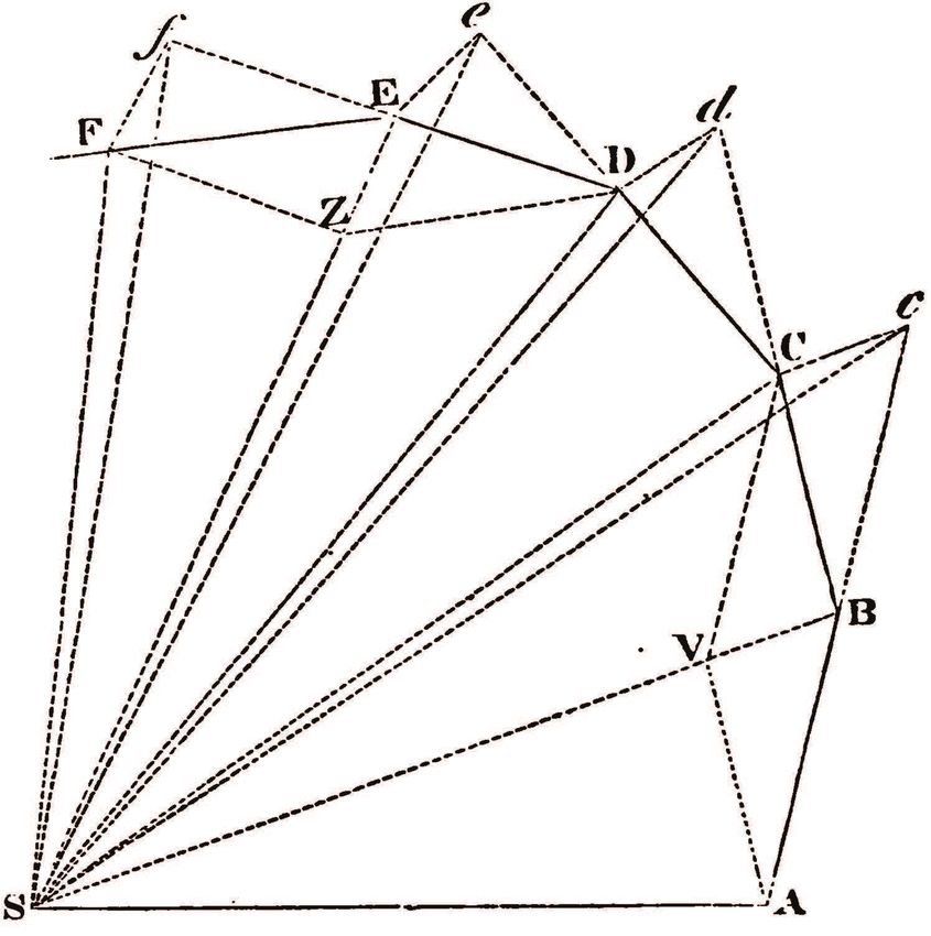
2FIG. 1. Newton’s iconic graphical construction; the Principia’s Proposition 1, Theorem 1, taken
from Ref.19 and further explained in the text.
Newton did not, that of using a graphical method to solve an inverse problem of determining
the orbit from a given force. A claim that has since repeated by Cooper16 .
However, Nauenberg’s conclusion was disputed by Erlichson17 , who argued that Hooke
had simply constructed an ellipse geometrically by uniformly squeezing a circle and found
that the resulting vertices can be fitted according to Newton’s graphical method for a linear
force. Therefore, at most, what Hooke has solved is the direct problem, that given a centered
elliptical orbit, the force can be determined to be linear.
It is difficult even for experts to evaluate each side of the argument. Clearly, Hooke
has drawn a circumscribing circle in Fig.2. His orbital vertices α, β, κ, etc., were marked
precisely at midpoints18 of chord lines drawn between the central vertical to points on
the circle’s circumference, a known method (an affine transformation) of constructing an
ellipse. This fact was admitted as possible by Nauenberg in his original article14 and in his
3FIG. 2. Hooke’s unpublished manuscript, taken from Ref.5, showing his construction of an ellipse
whose vertices α, β and κ, etc., were marked at half the distances between the central vertical and
the circumscribing circle. For a more detailed description, see Nauenberg14 and Erlichson17 .
4rebuttal20 to Erlichson. However, Hooke’s text accompanying the diagram did mention that
each impulse produced by the attractive body is proportional to the radial distance.
A related puzzle is that if Hooke had been successful in graphing the orbit of a linear
force, why didn’t he apply it to the all-important inverse-square force? Many of Hooke’s
supporters7,9,14 believed that he did, but those drawings were simply lost. When referring
to Fig.2, Purrington21 ventured that “It is limited to the case of a linear force, and while
no similar calculation is known for the crucial case of the inverse-square force, such a proof
would be not terribly more difficult, and it does not require a great leap of faith to suppose
that such a proof by Hooke once existed.”
Fortunately, modern understanding of Newton’s graphical construction as a symplectic
integrator can now shed light on these issues. A symplectic integrator is a canonical trans-
formation which seeks to integrate Hamilton’s equation to obtain the system’s coordinate
and momentum as a function of time. The crucial point about a symplectic integrator is
that, the trajectory it produces, while only approximate for the original Hamiltonian it in-
tended to solve, is exact for a Hamiltonian which is the original Hamiltonian plus some error
terms. The key contribution of this work is to show that, when Newton’s graphical method
is applied to a linear force, its corresponding Hamiltonian with error terms remained har-
monic and exactly solvable. This means that the trajectory produced by Newton’s graphical
method can be determined analytically. By comparing this analytical solution to Hooke’s
construction, one can decide whether Hooke has applied Newton’s method and obtained the
correct elliptical orbit. Similarly, one can repeat the analysis for the inverse-square force,
and ascertain whether Newton’s graphical method can produce an ellipse with the force at
one of its focus. In short, this work substantiated many of Erlichson’s17 original criticisms
with precise analytical findings made possible by the modern development of symplectic
integrators.
In the following, Sect.II reviews Newton’s graphical construction, explain how its ge-
ometric formulation is translated into algebraic expressions, and why it is a symplectic
integrator. Sect.III gives the analytical form of the elliptical orbit produced by Newton’s
graphical method for a linear force. Sect.IV compares Newton’s graphical construction of
an upright symmetric orbit, similar to the one found in Hooke’s manuscript. Sect.V repeats
the orbit construction for the inverse square force. Sect.VI summaries key conclusions of
this work.
5II. NEWTON’S GRAPHICAL CONSTRUCTION AS A SYMPLECTIC INTE-
GRATOR
Newton’s graphical construction, the celebrated Proposition 1, Theorem 1 of the Principia
is shown in Fig.1. In order to fully appreciate its relationship to symplectic integrators, it is
necessary to review details of its construction. Newton stated that when a planet is initially
moving at a given velocity, it will move from A to B in a given time interval. If there were no
force acting on it, then by Newton’s first law, it will continue to move in the same direction
in the next time interval from B to c, with distance Bc equal to AB. Triangles SAB and SBc
(S=Sun) then have equal area; since their bases AB and Bc are of equal length, and both
have the same apex S. However, if at B, the planet is acted on by a force impulse directed
toward S along BS, instantaneously changing the planet’s velocity so that it is moving along
BC instead, then it will arrive at C. The position C (this is the key point), is along the new
direction BC such that cC is parallel to BS. Since cC is parallel to BS, triangles SBc and
SBC have the same perpendicular height to their common base SB. Therefore, their areas
are equal. It then follows that the area SBC equals area SAB, since both are equal to area
SBc. Repeating this process for D, E, etc., shows that for any central force, the discrete
trajectory ABCDE will sweep out equal areas SAB, SBC, SCD, SDE, etc., at equal time
intervals, thus proving Kepler’s second law for any time interval.
One can illustrate this construction concretely in Fig.3 for a central linear force with
acceleration exactly equal to the radial distance. One can take the initial position as r0 =
(0, 2), initial velocity v0 = (1, 0) and time step ∆t = 1. Red dots A, B, C, D, E, and F
are discrete positions generated by the the analytical forms (1) and (2) given below, which
anyone can plainly see as precisely matching Newton’s graphical construction as follow:
Starting at position A, the planet moves at constant velocity vx0 = 1 for time ∆t = 1 to
position B. If there were no force, the planet would have drifted at the same velocity to c in
another ∆t time interval. However, at B, the central force exerted an impulse exactly equal
to the distance BO, thereby changing velocity direction from AB to BC instantaneously.
Because of this new velocity, the planet actually moved from B to C in time interval ∆t.
The position C is precisely along the new trajectory Bd such that cC is parallel to BO. With
the new velocity BC, if there were no force, the planet would again drift on from C to d.
However, the impulse CO at C, changes the velocity BC to CD, and the planet actually
64 b
3
a A B c
2
1
0 F C
y
O
−1
−2 f d
E D
−3
−4 e
−4 −3 −2 −1 0 1 2 3 4
x
FIG. 3. Red dots are orbital positions produced by Newton’s graphical method for a linear central
force at ∆t = 1. The green ellipse is its analytical description. The black ellipse is the correct
orbit. See text for details.
arrived at D, and so on. The unit triangular areas OAB, OBC, OCD, ODE, OEF, OFA,
sweep out by the polygonal trajectory ABCDEF, are obviously equal. The black and green
ellipses will be discuss below.
Newton’s graphical construction consisted of iterating two steps: 1) Drifting at a constant
velocity for time ∆t and 2) Changing the velocity according to impulse a∆t instantaneously.
These are just Newton’s first and second laws respectively. As first noted by Nauenberg14 ,
these two steps, occurring at one time interval ∆t, can be identified analytically as
r′ = r + v∆t (1)
v′ = v + a(r′ )∆t. (2)
7For a central linear or inverse square force, a(r) = f (r)r, with f (r) = −ω 2 or f (r) = −k/r 3
respectively. Note that the updated position r′ is used immediately in a(r′ ) to update the
velocity. This sequential updating is at the heart of Newton’s graphical method, clearly
shown in Fig.1, but easily overlook. The force impulse is evaluated at B, after drifting from
A, and evaluated at C, after drifting from B, and so on. Newton singles out the drift step
(1) first, then follow by the change in velocity (2) together with the next iteration of (1).
That is, Newton iterates his algorithm at successive ∆t to the rhythm of (1), (2)(1), (2)(1),
etc., always ending with (1) drifting into the final position with the updated velocity. For
example, if (2) were followed by by (1) again, one would get
r′′ = r′ + v′ ∆t = r + v∆t + v∆t + (a(r′ )∆t)∆t, (3)
corresponding to the initial position r drifted 2∆t at the original velocity v, then the impulse
(the change of velocity) a(r′ )∆t is evaluated at the previous position r′ , and drift for a time
∆t to the final position. This precisely corresponds to the initial drift from A to c in Fig.1,
then correcting the trajectory from c to C . Note that the trajectory correction (or deviation)
cC = (a(r′ )∆t)∆t, is parallel to the impulse a(r′ )∆t evaluated at the prior position r′ .
Equations (1) and (2) also gives an analytical proof of Kepler’s equal area law. Referring
to Fig.1, let SA = r and AB = v∆t, then area SAB = |r × v∆t|/2. After the updating
according to (1) and (2), the area SBC = |r′ × v′ ∆t|/2 will be equal to that of SAB, since
r′ × v′ = r′ × (v + f (r ′)r′ ∆t) = (r + v∆t) × v = r × v, (4)
independent of the actual form of f (r). Thus, as it is well known, Kepler’s equal area law
is just angular momentum conservation.
This equal area law is is not evident in Hooke’s notion of “compounding” inertial and
attractive motions. For example, if one were to replace (2) by v′ = v + a(r)∆t, which
evaluates the force at the old position r, and not at the updated position r′ , then the result
would be the disastrous Euler algorithm,22 with no conservation of angular momentum, and
for a non-constant force, unstable at any ∆t, no matter how small. Yet, such a mathematical
algorithm would still be consistent with Hooke’s notion of “compounding” inertial motion
with an attractive force. Therefore, for orbital motion around a central force, what is needed,
but missing from Hooke’s hypothesis, is a special way of “compounding” that would conserve
angular momentum, i.e., respecting Kepler’s area law. Even if he had been influenced by
8Hooke’s idea of “compounding”, Newton’s way of “compounding”, of incorporating Kepler’s
second law, is entirely due to his own genius.
Newton’s graphical construction, as described earlier, and obvious from its analytical form
(1)-(2), is that it is sequential. As emphasized in Ref.22, this is a defining hallmark of being a
symplectic integrator. As a matter of fact, it is one of two fundamental, long known first order
symplectic integrator.22 (The other one, Cromer’s algorithm,23 is the sequential updating of
(2) followed by (1).) When Nauenberg14 first wrote down (1)-(2), he did not know that they
corresponded to a symplectic integrator. Those who knew (1)-(2) as a symplectic integrator
were unaware of its connection to Newton’s graphical construction. This work, aware of this
connection, also knows the Hamiltonian which govern the trajectories produced by (1)-(2).
If the original motion is governed by the Hamiltonian H = p2 /2m + V (r) then the trajec-
tory generated by Newton’s algorithm (1)-(2) is governed by the approximate Hamiltonian,24
1
HA = H − p · a(r)∆t + O(∆t2 ), (5)
2
where v = p/m and a(r) = F(r)/m. For the harmonic potential V (r) = mω 2 r2 /2, the
above Hamiltonian with only the first order ∆t term, is exact for Newton’s algorithm. (All
higher order ∆t terms only sum to an overall multiplicative constant25,26 .) Thus, as will be
shown in the next Section, for a linear central force, the trajectory produced by Newton’s
graphical method is known analytically.
III. ELLIPTICAL ORBITS OF A LINEAR FORCE
Consider a central linear force in two dimension, the Hamiltonian with unit mass is
1 2
H= v + ω 2 r2 , (6)
2
with trajectory given by
v0
r(t) = r0 cos(ωt) + sin(ωt). (7)
ω
For r0 = (0, y0 ), v0 = (vx0 , 0) one has
vx0
x(t) = sin(ωt), y(t) = y0 cos(ωt), (8)
ω
which is the elliptical orbit !2 !2
x y
+ = 1. (9)
vx0 /ω y0
9For ω = 1, vx0 = 1 and y0 = 2, this is the exact orbit x2 + (y/2)2 = 1, the black ellipse,
shown in Fig.3.
The Hamiltonian (5) corresponding to Newton’s algorithm is
1
HA = (v2 + ω 2r2 + ∆tω 2 v · r)
2 !
1 ω 2 ∆t 2 2 ω 2∆t2 2
= (v + r) + ω (1 − )r , (10)
2 2 4
which can be rewritten as
1 2
HA = e + Ω2 r2 ,
v (11)
2
q
e = v + ω 2 ∆tr/2 and Ω = ω 1 − ω 2 ∆t2 /4. Therefore as long |∆t| < 2/ω, this remains
with v
a harmonic oscillator with angular frequency Ω and trajectory
v
e0
r(t) = r0 cos(Ωt) + sin(Ωt), (12)
Ω
e 0 = v0 + ω 2 ∆tr0 /2. Here, HA is the Hamiltonian exactly conserved by Newton’s
where v
algorithm (1)(2) in that HA (r′ , v′ ) = HA (r, v).
For a given ∆t, and with the same initial conditions as above, the trajectory generated
by Newton’s algorithm (12) is
vx0
x(t) = sin(Ωt),
Ω
ω 2 ∆ty0
y(t) = y0 cos(Ωt) + sin(Ωt), (13)
2Ω
which is a closed elliptical orbit
!2 2
2
x y − ( ω 2v∆ty 0
)x
+ x0 = 1. (14)
vx0 /Ω y0
Thus Newton’s graphical construction, when applied to a linear central force, will always
yield orbital positions on a closed ellipse, as long as |∆t| < 2/ω.
This surprisingly result is the key contribution this work. Normally, when one applies a
numerical method, one has no expectation that it will yield anything resembling the exact
result at a large value of ∆t. To illustrate this we compare Newton’s graphically constructed
orbit in Fig.4 with trajectories produce by other well-known algorithms.
That’s why Erlichson17 remarked that, had Hooke used Newton’s method to solve the
inverse problem, “then there would be no requirement that the vertex points lie on-orbit [on
108
6
4
Newton
2
RK2
0 Euler
RK4
y
−2
−4
−6
−8
−10
−8 −6 −4 −2 0 2 4
x
FIG. 4. Comparing Newton’s graphical method (red) with Euler’s algorithm (blue), second-order
Runge-Kutta algorithm RK2 (orange) and fourth-order Runge-Kutta algorithm RK4 (light blue)
at ∆t = 1 for 18 iterations. Only Newton’s graphical construction remains a closed orbit.
the elliptical orbit]”. He therefore thought that Hooke’s results were too good to be true, and
can’t possibly from using Newton’s method. However, Nauenberg20 , also observed that “In
general, a graphical construction can give only an approximation to such a curve, but in this
case, the resulting vertex points of the polygon lie on an ellipse.” Since Hooke’s construction
is consistent with using a linear force, Nauenberg drawn the opposite conclusion that Hooke
had produced an elliptical orbit using Newton’s graphical method. Both conclusions were
wrong because both tacitly assumed that the ellipse drawn by Hooke is the correct orbit for
the linear force. They did not anticipate the result of this work, that Newton’s graphical
method, when applied to a linear force, will always yield positions on a closed ellipse, but
that ellipse is not the correct elliptical orbit!
114 b
3
a A B c
2
1
0 F
y
O C
−1
−2
f E D d
−3
−4 e
−4 −3 −2 −1 0 1 2 3 4
x
FIG. 5. linear force orbit (red dots) generated by Newton’s graphical method at ∆t = 1 with a
pair of symmetric initial positions A and B.
That ellipse, (14), is shown in Fig.3 as the green ellipse encompassing the polygonal orbit
ABCDEF. This green ellipse approaches the correct black ellipse only in the limit of ∆t → 0.
At any finite ∆t, this ellipse has a characteristic “tilt” from the vertical because its first step
r1 = (vx0 ∆t, y0) is asymmetric with respect to the y-axis. Therefore, as originally noted
by Erlichson17 , had Hooke just applied Newton’s graphical method, using similar initial
conditions, he would not have gotten an upright, left-right symmetric ellipse (to be discuss
in the next Section). The reason why Hooke did not choose such a natural starting point is
clear; he did not apply Newton’s graphical method.
12IV. THE UPRIGHT SYMMETRIC ELLIPSE
Instead, Hooke chooses the initial position to be r0 = (−vx0 ∆t/2, y0), so that after step
(1) of Newton’s algorithm, r1 = (vx0 ∆t/2, y0 ). This then guarantees that the first two
vertices of the polygonal orbit will be symmetric with respect to the y-axis. The resulting
orbit from (12) is then given by
ω 2x(t) ω 2 ∆t
=− cos(Ωt) + Ω sin(Ωt),
vx0 2
y(t) ω 2 ∆t
Ω = Ω cos(Ωt) + sin(Ωt). (15)
y0 2
The cross terms cancel when both sides are squared and added. Since Ω2 + ω 4∆t2 /4 = ω 2,
this gives remarkably,
!2 2
x y
+ q = 1, (16)
vx0 /ω y0 / 1 − ω 2∆t2 /4
which differs from the exact orbit of (9) only by the factor (1 − ω 2 ∆t2 /4)1/2 ! Such a starting
condition not only produces an upright symmetric ellipse, but also dramatically improved
the algorithm from first to second order in ∆t! There is now no “tilt” proportional to ∆t.
Using the same parameter values as in Fig.3, the algorithm’s orbit (16) is shown as the green
ellipse ABCDEF in Fig.5. This green ellipse is now much closer to the black ellipse, but it
is still not the correct orbit! The discrete graphical constructed points are again A, B, C,
D, E and F. It is now even more obvious that Kepler’s equal area law is obeyed: the areas
swept out are equal area segments of the hexagon ABCDEF.
However, the choice of ∆t = 1, which divided the algorithm’s orbit exactly into six
segments, is rather special. Although the orbit of the algorithm is determined by Ω, the
actual angular velocity of the algorithm is given by ΩA , defined by25
cos(ΩA ∆t) = 1 − ω 2∆t2 /2. (17)
Therefore, if one were to chose a ∆t such that T /∆t = n, where the period T = 2π/ΩA ,
then one must have ΩA ∆t = 2π/n or
s
1 h 2π i
∆t = 2 1 − cos , (18)
ω n
which gives ∆t = 1 for ω = 1 and n = 6. For any other arbitrary value of ∆t, say
∆t = 0.8, ∆t would not divide the period evenly. This is shown in Fig.6. The positions
132 A B
1
C
0
y
G
−1
D
−2 F
E
−2 −1 0 1 2
x
FIG. 6. Same as Fig.5 but with ∆t = 0.8.
produced by the graphical method still lie on the predicted green ellipse (16), but are no
longer left-right symmetric. This is another of Erlichson’s criticism.17 Therefore, if Hooke
were simply applying Newton’s graphical method, he would have gotten, either the tilted
polygonal orbit of Fig.3, or an upright but left-right asymmetric polygonal orbit of Fig.6.
The fact that Hooke is marking off parallel chord lines in Fig.2 shows that he is using the
circumscribing circle to construct left-right symmetric elliptical vertices17 . But such vertices
are highly unlikely, because unless ∆t is specifically chosen according to (18), the resulting
orbital vertices cannot be left-right symmetric.
Nauenberg14 also claimed that Hooke’s diagram (Fig.2) proved the area law differently
from Newton. Newton’s graphical proof of Kepler’s area law is general, true for any central
force. Hooke’s demonstration of the area law is specific to his ellipse construction. This is
because Hooke is uniformly squeezing the circle; areas of pie-like slices on the circumscribing
14circle are all squeezed by the same factor into areas of pie-like slices on the ellipse. Therefore,
if the original slices on the circle are of equal area, then the squeezed slices on the ellipse
are also of equal area. This is just a geometric consequence of Hooke’s construction, not a
general embodiment of Kepler’s equal area law.
V. THE INVERSE-SQUARE FORCE
What happens when Newton’s graphical method is applied to the gravitational force?
Why didn’t Newton use it to compute Kepler’s orbit? Since Newton has claimed in Corol-
lary 1 of Book 1’s Proposition 13, that an inverse-square force would yield an elliptical
orbit, he would not have felt the need to use his graphical method to prove anything else
except Kepler’s second law. However, others, such as Weinstock27 , have argued that New-
ton’s Corollary 1 is not a proof, and that Newton never solved the inverse problem for the
inverse square force in the Principia. But is it possible that Hooke could have used the
same graphical method to produce an orbit for the inverse-square force, as suggested by
Purrington21 ?
Nauenberg14 has shown that if ∆t is too large, the orbit will not be elliptical near the
force center. Here, we can again study the trajectory produced Newton’s graphical method
in greater details by analyzing the approximate Hamiltonian (5). For the inverse-square
force, the approximate Hamiltonian is
1 k ∆t kr · v
HA = v 2 − + 3
+ O(∆t2 ). (19)
2 r 2 r
In the linear force case, the first-order error term (∝ v · r) is less singular (as r → ∞)
than the original potential (∝ r2 ), and therefore the approximate Hamiltonian can still be
redefined as harmonic (11) with a potential ∝ r2 . This then produces at most, a tilted, but
still closed elliptical orbit (14). By contrast, for the gravitational force, the first-order ∆t
term above (∝ v · r/r 3 ) is more singular (as r → 0) than the original potential (∝ 1/r) and
can never be redefined so that the approximate Hamiltonian is having a potential ∝ 1/r.
By Bertrand’s theorem28 ,if the potential is neither r 2 nor 1/r exactly, then the orbit cannot
be closed. Thus when applied to the gravitational force, Newton’s graphical method, even
if ∆t is sufficiently small so that the trajectory can go around the force center, will not yield
a closed orbit. The orbit will remain open and and just precess. For the kind of geometrical
152
1
y
0
−1
−3 −2 −1 0 1 2
x
FIG. 7. Inverse-square force orbits generated by Newton’s graphical method at ∆t = 0.5 (red)
∆t = 0.2 (blue-green) and ∆t = 0.01 (blue). See text for details.
construction that can be done by hand, one would not get a recognizable ellipse. This is
illustrated in Fig.7 for ∆t = 0.5, k = 1 and a symmetrical start with initial velocity reduced
to vx0 = 0.5. The exact orbit with eccentricity 1/2 given by
!2 !2
x y − 2/3
√ + = 1, (20)
2/ 3 4/3
can be produced by Newton’s algorithm (1)-(2) with ∆t = 0.01. The red dot trajectory
generated by ∆t = 0.5 also coincide with the correct orbit as it proceeds down the right
side of the ellipse. However, as noted by Nauenberg14 , this is no longer the case after the
trajectory passes below the force center at the origin. Further iterations show that the orbit
precesses counter-clockwise. After ≈5 periods, the semi-major axis has rotated 90◦ . (The
precession shown is actually due to the ∆t2 terms (not shown) in (19) because the ∆t term
16contribution vanishes after each period. To verify this ∆t2 -dependence, Fig.7 also shows
that the orbital precession for ∆t = 0.2 is roughly (0.5/.2)2 ≈ 6 times smaller than that of
∆t = 0.5.)
Thus when Newton’s graphical method is applied, the resulting trajectory differs greatly
depending on whether the central force is linear or inverse-square. For the inverse square
force a closed orbit is possible only for very small time steps, such as ∆t = 0.01, as shown
in Fig.7. However, such a time step is probably 50 times too small to be drawn by hand.
Most likely, a hand construction would resemble the red dot orbit in Fig.7, corresponding to
∆t = 0.5. In this case, the orbit will not close. Therefore, contrary to Purrington’s musing,
it is also unlikely that Hooke could have constructed by hand, a closed elliptical orbit for
the inverse square force.
VI. CONCLUSIONS
This work, by knowing the Hamiltonian which governs the trajectory of a symplectic
integrator, has shown that when Newton’s graphical method is applied to a central linear
force, the resulting trajectory is always an centered ellipse, just not the correct elliptical orbit.
By carefully comparing this analytically ellipse to Hooke’s drawing, this work substantiated
Erlichson’s conclusion that Hooke was trying to repeat what he had done before with a
circular orbit, that he was trying to follow an elliptical orbit in order to determine the
required force. He constructed an elliptical orbit, then found that, consistent with Newton’s
graphical construction, the required force is linear. This solves the direct, not the inverse
problem. Moreover, even this success is fortuitous; because by the same result above, it is a
peculiar property of Newton’s graphical method that any centered ellipse can be fitted to a
linear force.
When the same analysis is applied to the inverse square force, the result is drastically
different. When Newton’s graphical method is applied by hand to the inverse square force,
it is unlikely to yield a closed, elliptical orbit. This is the more likely reason why no similar
drawing for the inverse square force can be found in Hooke’s possession.
17ACKNOWLEDGMENTS
I thank my colleague Wayne Saslow, for initiated my interest in this work.
1 Johs Lohne, “Hooke versus Newton”, Centaurus, 7 (1960), 6-51.
2 R. S. Westfall, “Hooke and the Law of Universal Gravitation: A Reappraisal of a Reappraisal,”
British Journal for the History of Science, 3 (1967) 245–261.
3 F. F. Centore, Robert Hooke’s Contributions to Mechanics: A Study in Seventeenth Century
Natural Philosophy, Martinus Nijhoff, The Hague, 1970.
4 Robert Hooke: New Studies, M. Hunter and S. Schaffer, ed., (Woodbridge, England and
Wolfeboro, USA, The Boydell Press, 1989)
5 Patri J. Pugliese, “Robert Hooke and the Dynamics of Motion in a Curved Path,” in Ref.4,
181–205.
6 O. Gal, Meanest Foundations and nobler superstructures, Kluwer Academic Publishers, Dor-
drecht, Netherlands, 2002.
7 M. Cooper, Robert Hooke and the Rebuilding of London, Sutton Publishing, Phoenix Mill,
England, 2003.
8 Robert Hooke: Tercentennial Studies M. Cooper and M. Hunter ed., (Aldershot, England and
Burlington, USA, Ashgate Publishing Company, 2006)
9 R. D. Purrington, The First Professional Scientist: Robert Hooke and the Royal Society of
London, Birkhäuser Verlag AG, Basel-Boston-Berlin, 2009.
10 H. W. Turnbull, ed., The Correspondence of Isaac Newton. Vol. II. 1676–1687 (Cambridge,
Cambridge University Press, 1960).
11 J. B. Barbour, The Discovery of Dynamics, P.542, Oxford University Press, New York, 2001.
12 M. Cooper, ibid, Chapter 7, footnote 23, P.230.
13 O. Gal, ibid, P.20.
14 M. Nauenberg, “Hooke, Orbital Motion and Newton’s Principia”, Am. J. Phys. 62 (1994) 331-
350.
15 M. Nauenberg, “Robert Hooke’s Seminal Contribution to Orbital Dynamics”, Phys. Perspect.
7 (2005) 4–34.
1816 M. Cooper, ibid, P.82.
17 H. Erlichson, “Hooke’s September 1685 Ellipse Vertices Construction and Newton’s Instanta-
neous Impulse Construction”, Historia Mathematica 24 (1997) 167–184.
18 M. Nauenberg in Ref.14, P.342 and footnote 33; H. Erlichson in Ref.17, P.175.
19 https://commons.wikimedia.org/w/index.php?curid=9485680
20 M. Nauenberg, “On Hooke’s 1685 Manuscript on Orbital Mechanics,” Historia Mathematica 25
(1998) 89–93.
21 R. D. Purrington, ibid, P.186
22 Siu A. Chin, “Structure of numerical algorithms and advanced mechanics”, Am. J. of Phys. 88,
883 (2020); https://doi.org/10.1119/10.0001616
23 Alan Cromer, “Stable solutions using the Euler approximation”, Am. J Phys. 49, 455-459
(1981).
24 H. Yoshida, “ Recent progress in the theory and application of symplectic integrators”, Celest.
Mech. Dyn. Astron. 56, 27-43 (1993).
25 S. R. Scuro and S. A. Chin, “Exact evolution of time-reversible symplectic integrators and their
phase errors for the harmonic oscillator”, Phys. Lett. A 397, 342-403 (2005)
26 Kenneth M. Larsen, “Note on stable solutions using the Euler approximation”, Am. J. Phys.
51, 273 (1983).
27 R. Weinstock, “Dismantling a centuries-old myth: Newton’s Principia and inverse-square or-
bits”, Am. J. Phys. 50, 610 (1982).
28 J. Bertrand, “Thórm̀e relatif au mouvement d’un point attiré vers un centre fixe,” C. R. Acad.
Sci. 77, 849-853 (1873)
19You can also read


