A Study to Enhance the Nitrate-Nitrogen Removal Rate without Dismantling the NF Module by Building a PFSA Ionomer-Coated NF Module - MDPI
←
→
Page content transcription
If your browser does not render page correctly, please read the page content below
Article

A Study to Enhance the Nitrate-Nitrogen Removal Rate
without Dismantling the NF Module by Building a PFSA
Ionomer-Coated NF Module
In-Kee Park 1,†, Jian Hou 1,†, Jaehan Yun 1, Hee-Dae Lee 2 and Chang-Hyun Lee 1,*

                                          1 Department of Energy Engineering, Dankook University, Cheonan 31116, Korea;
                                            inkee0149@gmail.com (I.-K.P.); houjimmy@naver.com (J.H.); ruri7220@naver.com (J.Y.)
                                          2 Coway R & D Center, Seoul 08826, Korea; lhd1371@coway.co.kr

                                          * Correspondence: chlee@dankook.ac.kr; Tel.: +82-41-550-3683
                                          † These authors have contributed equally to this work.

                                          Abstract: Water resource pollution by nitrate-nitrogen, mainly caused by anthropogenic causes, in-
                                          duces eutrophication of water resources, and indicates the degree of organic pollution. Therefore,
                                          this study devised a method for coating PFSA ionomer with excellent chemical resistance without
                                          disassembling the module to improve the removal rate of nitrate-nitrogen in water by using a cyclic
                                          coating method on a commercially available nanofiltration membrane (NF membrane) module.
                                          Nafion was prepared as a supercritical fluid dispersion using a high-temperature and high-pressure
                                          reactor, and the particle size and the degree of dispersion of the dispersion were analyzed by DLS.
                                          The crystallinity was confirmed through XRD by drying the dispersion in the liquid state. After the
                                          dispersion was prepared as a membrane according to the heat treatment conditions, the character-
                                          istics according to the particle size were analyzed by tensile strength and TEM. The nitrate-nitrogen
Citation: Park, I.K.; Hou, J.; Yun, J.;
                                          removal rate of the NF membrane module coated with the dispersion was increased by 93% com-
Lee, H.D.; Lee, C.H. A Study to
                                          pared to that before coating. Therefore, the result showed that the cycle coating method devised in
Enhance the Nitrate-Nitrogen
Removal Rate without Dismantling
                                          this study could efficiently coat the already commercialized module and improve performance.
the NF Module by Building a PFSA
Ionomer-Coated NF Module.                 Keywords: NF module; supercritical fluid; dispersion; PFSA ionomer; nitrate-nitrogen removal
Membranes 2021, 11, 769. https://
doi.org/10.3390/membranes11100769

Academic Editor: Tae-Hyun Bae             1. Introduction
                                                Nitrogen is an essential component of plant and animal proteins and is a vital com-
Received: 26 August 2021
                                          ponent of organisms but is toxic when contained in excessive amounts [1]. In particular,
Accepted: 5 October 2021
                                          artificial contamination caused by fertilizer spraying and livestock wastewater is the lead-
Published: 9 October 2021
                                          ing cause [2], and it is the causative agent of methemoglobinemia (cyanosis) when infants
Publisher’s Note: MDPI stays neu-
                                          ingest wastewater [3]. Nitrate-nitrogen indicates the degree of contamination according
tral with regard to jurisdictional
                                          to the content of nitrogen compounds, such as nitrogen oxides and ammonia, in water or
claims in published maps and institu-     soil [4]. The concentration of nitrate-nitrogen is limited to 10 ppm or less based on water
tional affiliations.                      quality standards [5]. However, as a result of a 2004 World Health Organization (WHO)
                                          survey of 2000 of the world’s drinking water sources [6], 30% of them had a nitrate con-
                                          centration of 24 mg/L (24 ppm) or higher, and the problem of nitrate-nitrogen continues
                                          to be an issue [6].
Copyright: © 2021 by the authors. Li-           So far, the methods to remove nitrate-nitrogen in water include biological denitrifi-
censee MDPI, Basel, Switzerland.          cation [7], ion exchange, reverse osmosis, etc., and membrane technology and electrodial-
This article is an open access article    ysis methods are most commonly used [2]. The biological denitrification method uses a
distributed under the terms and con-      large amount of disinfectant, so there is a stability problem [8]. The ion exchange method
ditions of the Creative Commons At-       is disadvantageous as divalent sulfate ions are preferentially removed before nitrate-ni-
tribution (CC BY) license (http://crea-
                                          trogen, producing regeneration waste [9]. It is not easy to dispose of the used regeneration
tivecommons.org/licenses/by/4.0/).
                                          waste since it contains a large amount of nitrate-nitrogen. Once released, it causes soil

Membranes 2021, 11, 769. https://doi.org/10.3390/membranes11100769                                              www.mdpi.com/journal/membranes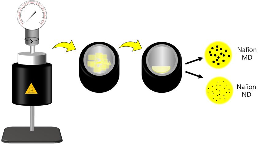
Membranes 2021, 11, 769                                                                                         2 of 10

                          contamination and eutrophication of water quality [10]. The reverse osmosis method is
                          used as the most effective method, together with the electrodialysis method [11]. Still, high
                          pressure or additional electrical energy is required to treat the contaminated water, so the
                          operation cost is considerable [9]. Therefore, the cycle-coating method used in this study
                          has the advantage of being able to easily coat the commercially available NF membrane
                          module (nanofiltration membrane module) without disassembling it and through this, a
                          higher removal rate of nitrate-nitrogen can be expected.
                                A perfluorosulfonic acid ionomer (PFSA ionomer) consists of a polytetrafluoroeth-
                          ylene (PTFE) backbone having a chemically strong structure [12] and a perfluoro side
                          chain containing a sulfonic acid group (-SO3H) at the end [13]. The perfluoro structure
                          containing sulfonic acid induces a hydrophobic/hydrophilic microphase separation form
                          for fast proton conduction [14]. The high electronegativity of the F atom makes it easy to
                          release a proton from the sulfonic acid group [15]. It is expected that these PFSA ionomers
                          will be coated on the NF membrane module in a dispersed form in an aliphatic alcohol-
                          water mixture to prevent the permeation of nitrate-nitrogen. In addition, as PFSA iono-
                          mers have higher reliability than hydrocarbons in chemical and thermal stability, as
                          demonstrated in several kinds of literature [16], Nafion dispersions (e.g., 5 wt% Nafion
                          D521, DuPont, USA) are commonly used [17]. However, Nafion dispersions have difficul-
                          ties controlling the particle size and dispersibility characteristics, and attempts have been
                          made to control particle size or dispersibility through chemical and physical routes [18].
                                Supercritical fluids (SCFs) have fast heat and material movement, low viscosity, and
                          high permeability into micropores due to their unique properties, such as high diffusion
                          coefficients and other liquids and gases [19]. In addition, it is widely used in industry and
                          research [20] because it can solve the technical problems of adverse effects on the environ-
                          ment or low efficiency in the existing reaction process and is particularly useful for the
                          synthesis of unique pharmaceuticals, polymers, and nanomaterials [21]. Therefore, in this
                          study, a Nafion ionomer dispersion having colloidal particles smaller than a commercially
                          available Nafion dispersion obtained by treatment with water-soluble aliphatic alcohol
                          studied in the past was prepared through supercritical technology. Then, we coated the
                          Nafion ionomer dispersion on the surface of the separation membrane without separating
                          the commercially available NF membrane module, using the cyclic coating method, and
                          examined the nitrate-nitrogen removal properties in water.

                          2. Materials and Methods
                          2.1. Materials
                              1-propanol (NPA, >99.9%) and isopropyl alcohol (IPA, >99.7%) were purchased from
                          Sigma Aldrich Co. (Saint Louis, MA, USA) and used without further purification. The
                          sodium nitrate (NaNO3, >99.9%), calcium chloride dihydrate granular (CaCl2 2H2O,
                          >98%), and magnesium sulfate heptahydrate (MgSO4 7H2O, >99%) were purchased by
                          Daejung Chemical & Metal. Co. Ltd., Siheung-si, Korea. The NF membrane module (NF
                          module 8 inch, NF8S) was provided by Coway Co., Ltd., Seoul, Korea. The deionized wa-
                          ter (D.I. water) used to prepare and wash the dispersion was prepared using an ultrapure
                          water manufacturing apparatus Milli-Q (Progard® T3, Millipore, Darmstadt, Germany).
                          Nafion 117 film (Dupont Co., Wilmington, NJ, USA) was used to prepare a PFSA ionomer
                          dispersion for coating the NF membrane module.

                          2.2. PFSA Ionomer Dispersion Preparation and Analysis
                                The PFSA ionomer dispersion used to prepare the coating layer of the NF module
                          was made with Nafion117 as liquid SCFs through a supercritical dispersion process. To
                          prepare Nafion117 as SCF, it was prepared by mixing NPA and D.I. water as solvents in
                          a high-pressure/high-temperature reactor (4560 Mini-Bench Reactor System, PARR, Mo-
                          line, IL, USA) at a volume ratio of 1:3 (Figure 1). The particle size of the PFSA ionomer
                          dispersion prepared in a high-pressure/high-temperature reactor was confirmed using
Membranes 2021, 11, 769                                                                                           3 of 10

                          dynamic light scattering (DLS, Zetasizer Nano ZS, Malvern, Worcestershire, UK). Nafion
                          micro-dispersion ionomer solution (Nafion MD) and Nafion nano-dispersion ionomer so-
                          lution (Nafion ND) were named according to the dispersed particle size. After drying the
                          prepared ionomer dispersion, crystallinity and D-spacing analysis were performed using
                          an X-ray diffraction analyzer (Ultima IV, Tokyo, Japan). XRD analysis was measured at
                          5°/min in the 5–30° scan range at 35 mA and 40 kV, and the degree of crystallinity (Xc) in
                          the XRD diffraction pattern obtained through the analysis was calculated using the fol-
                          lowing Equations (1) and (2) [13]:
                                                                                      4
                                                         Diffraction vector q                                         (1)
                                                                                    sin θ/2

                                                   Crystallinity                                                      (2)

                          Figure 1. Preparation process schematic diagram of Nafion ionomer micro/nano-dispersions.

                                In Equation (1), λ represents the wavelength of Cu-Ka light used for analysis, and
                          Ia(q) and Ic(q) represent the peak intensities of amorphous and crystalline wavelengths,
                          respectively. The degree of crystallinity was expressed by dividing the crystal scattering
                          area by the sum of the crystal and amorphous scattering areas. At this time, 2θ values
                          corresponding to crystalline and amorphous in the XRD diffraction pattern of the PFSA
                          ionomer dispersion are 16° and 17.5°, respectively.

                          2.3. NF Membrane Module Coating
                                As a coating solution for forming the PFSA ionomer layer on the NF membrane mod-
                          ule, a PFSA ionomer dispersion was prepared at 5 wt.% using a solvent containing a 55:45
                          composition ratio of NPA and D.I. water. Then, after washing for 10 min with D.I. water
                          through the inlet and drain of the membrane module, the coating solution was circulated
                          at 100 mL/min for 30 min to coat and dried in an oven at 85 °C for three days (Figure 2).
                          In order to measure the basic properties of the NF membrane coating layer, a membrane
                          was prepared under similar conditions using PFSA ionomer dispersion. The membrane
                          prepared under similar conditions was developed through solidification in a convection
                          oven for 24 h at 85 °C, the same temperature condition applied to the preparation of the
                          ionomer layer.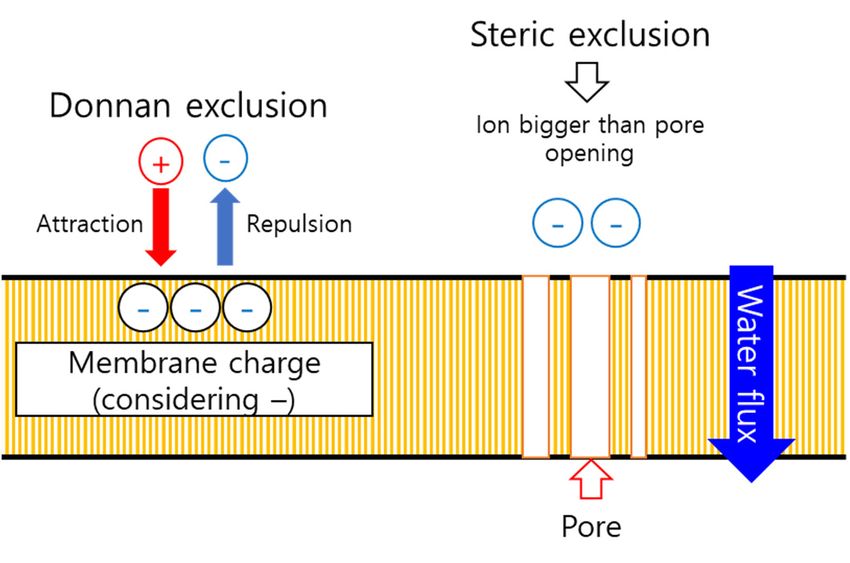
Membranes 2021, 11, 769                                                                                      4 of 10

                          Figure 2. NF membrane module coating process via a simple circulation process.

                                Small-angle X-ray scattering (SAXs, Model Bl 4C SAXs II, Pohang, Korea) was used
                          to analyze the inter-domain distance, which means the average distance between the hy-
                          drophilic domains of the coating layer. The X-ray beam had power of 3.0 GeV, a wave-
                          length of 0.07 nm, 1 × 10¹² ph/sec, and a beam flux size of 100 (V) μm × 300 (H) μm, and
                          the sample-detector distance (SDD) between the sample and the detector was set to 1 m.
                          Here, the sample was stacked to a thickness of 100–120 μm and was sampled with an area
                          of 1 × 1 cm2. The SAXs profile result was calculated using Bragg’s equation as in Equation
                          (3), which corresponds to q(1)max [22]:
                                                                              2
                                                                                                                 (3)
                                                                             1
                                The cross-section of the NF membrane was measured at an acceleration voltage of 20
                          kV using a scanning electron microscope (SEM, Scanning Electron Microscope, JEOL,
                          JSM-6360, Tokyo, Japan). The sample was attached to a double-sided carbon tape (Nishin
                          EM, Tokyo, Japan) and coated with platinum (Pt) for pretreatment. In addition, the chem-
                          ical composition of the sample was confirmed by energy-dispersive X-ray spectroscopy
                          (EDS).
                                Additionally, to confirm the morphology of the membrane prepared from the iono-
                          mer dispersion, the sample was measured at an acceleration voltage of 120 kV using a
                          transmission electron microscope (FE-TEM, Field-Emission Transmission Electron Mi-
                          croscopy, LIBRA 120, Carl Zeiss, Jena, Germany). The sample was sequentially pre-treated
                          (fixation, dehydration, and embedding) using dimethylaminoethanol (DMAE), nonenyl
                          succinic anhydride (NSA), diglycidyl ether polypropylene glycol (DER), and 4-vinylcy-
                          clohexene dioxide (VCD). The prepared sample was cut using an ultramicrotome
                          (EMUC7, Leica, Hessen, Germany) and then immersed in lead citrate to stain the ionic
                          domain of the sample, washed with D.I. water, and dried thoroughly before use.

                          2.4. Nitrate Removal Characteristics of Ionomer Coated Modules
                               A feed solution was prepared by mixing CaCl2-MgSO4 with 30 ppm NaNO3 so that
                          the hardness became 600 ppm to observe the nitrate-nitrogen removal characteristics of
                          the coated NF module. The prepared feed solution was passed through at a pressure of
                          3.54 kgf/cm2 at room temperature (25 °C), and the residual NaNO3 content was analyzed
                          to show the removal rate.

                          3. Results
                              Figure 3 shows the particle size distribution of the Nafion ionomer dispersion meas-
                          ured by DLS. Ionomer particles were classified into a small particle area (
Membranes 2021, 11, 769                                                                                              5 of 10

                          mixture showed a bimodal ionomer particle distribution regardless of the EW value. For
                          the Z-average size of each dispersion, the measured size of Nafion ND was relatively
                          smaller: 9.4 nm for Nafion MD and 1.76 nm for Nafion ND, because the Nafion MD small
                          particle distribution is relatively low (57%) compared to the Nafion ND’s distribution
                          (84%). Therefore, since the Nafion ND has smaller pores than the NF membrane with ex-
                          cellent SCF permeability, it seems to increase the nitrate-nitrogen removal rate more ef-
                          fectively when applied to the module coating with its higher permeability.

                                                 Concentration = 0.1 wt.%
                                            18
                                                      Nafion MD
                                                      Nafion ND
                                            15

                                            12              84%
                            Intensity [%]

                                                            57%
                                             9

                                             6

                                             3                                 43%
                                                                                16%
                                             0
                                                        0         1        2        3        4
                                                   10        10       10       10       10
                                                                  Size [nm]

                          Figure 3. Particle size distribution pattern of Nafion ionomers by DLS.

                                Figure 4a,b shows the results of measuring the crystallinity of Nafion MD and Nafion
                          ND using XRD. Nafion ND and Nafion MD have the same molecular weight. Still, like
                          Nafion ND, if the particles are entangled at the nano level, they will solidify, and the den-
                          sity of the polymer may increase. At the same time, the self-assembly between the hydro-
                          philic functional group and the hydrophobic functional group improves the regularity of
                          the polymer packing, thereby increasing the crystallinity [23]. Due to this effect, the crys-
                          tallinity of Nafion ND was increased by 16% to 41.8%, compared to 25.8% of Nafion MD.

                                                            (a)                                  (b)
                          Figure 4. XRD pattern of solidified-state Nafion ionomers; (a) Nafion MD, (b) Nafion ND.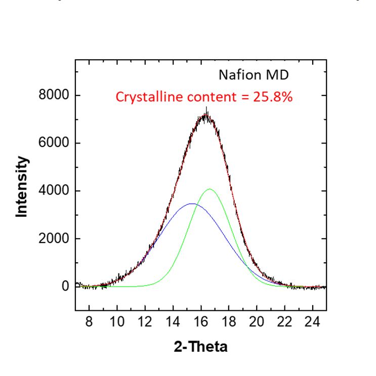
Membranes 2021, 11, 769                                                                                                   6 of 10

                                 Figure 5 shows the results of analyzing the tensile strength and elongation of the
                           membranes prepared according to the heat treatment temperature of Nafion MD and
                           Nafion ND. The micro-dispersion membrane (MD) showed tensile strength and elonga-
                           tion that were impossible to analyze under the heat treatment conditions below 220 °C,
                           and MD220 processed at 220 °C had a tensile strength of 19.5 MPa and an elongation of
                           199.1%. Additionally, unlike MD, the nano-dispersion membrane (ND) exhibited better
                           tensile strength than MD220 at a relatively low temperature (140 °C). According to the
                           particle size, the change of the heat treatment temperature is not smooth for heat transfer
                           to the inside of the particle in the case of MD because the size of the particles included in
                           the dispersion is relatively larger than that of ND. Therefore, it is considered that the in-
                           termolecular entanglement caused by the intermolecular interaction occurs at a higher
                           temperature in the MD compared to the ND. From the XRD results, the higher crystallinity
                           of ND than that of MD affected the increase in tensile strength [24]. However, since the
                           size of the ND particles is small, the effect on temperature is significant. Therefore, when
                           the ND was heat-treated at 160 °C or higher, the intermolecular bonding force due to de-
                           terioration should have decreased, which might cause lower tensile strength and elonga-
                           tion.

                                                   30                                              250
                                                                                Tensile strength
                                                                                Elongation

                                                   25
                                                                                                   200
                          Tensile strength [MPa]

                                                   20
                                                                                                         Elongation [%]

                                                                                                   150

                                                   15
                                                                                                   100
                                                   10

                                                                                                   50
                                                    5

                                                    0                                              0
                                                        MD140 MD220 ND140   ND150 ND160

                                                                    Sample

                           Figure 5. Mechanical property of solidified-state Nafion ionomers.

                                Figure 6 shows the TEM images of MD220 and ND140 prepared with PFSA ionomer
                           dispersion, and the samples were stained with lead citrate to understand the higher-reso-
                           lution film morphology. Due to lead citrate, complex ions were formed in the mixture of
                           sulfonic acid groups (-SO3), which causes Pb2+ ions contained in the colorant to bubble,
                           and the hydrophilic domain (SO3H) appears black. Regardless of the manufacturing
                           method, hydrophilic and hydrophobic regions were observed in all ionomer membranes.
                           Through TEM, the size of the hydrophilic domains of the sulfonic acid groups of MD and
                           ND were 6.5 and 2.8 nm, respectively, and this trend was similar to 5.9 and 3.1 nm in SAXS
                           analysis, which can measure the distance between bulky hydrophilic domains (Figure 7).
                           This meant that Nafion ND had a shorter ion pass way between hydrophilic domains than
                           Nafion MD; consequently, the distance of the whole domains was shortened [13]. In the
                           final NF membrane coating process, considering the ineffective influence on the coating
                           inside of pores due to the larger particle size of Nafion MD. Therefore, Nafion ND was
                           used that could effectively penetrate inside based on the small particle size.
Membranes 2021, 11, 769 7 of 10
Figure 6. TEM images of solidified-state Nafion ionomers; (a) MD220, (b) ND140.
10
10
Sample Interdomain distance
9
10 Micro-dispersion 5.9 nm
10
8 Nano-dispersion 3.1 nm
7
10
6 qmax
10
I [cm ]
-1
5
10
4 qmax
10
3
10
2
10
1
10
0
10
-1 -1 -1
10 2x10 3x10
q [Angstrom]
Figure 7. SAXS spectra of solidified-state Nafion ionomers.
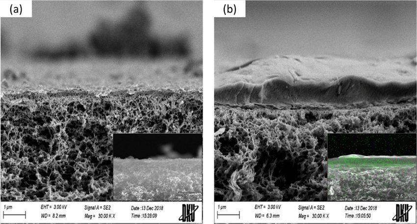
Figure 8 shows the results of SEM and EDS analysis. In SEM images, the Nafion ND
layer was formed on the surface of the NF membrane. Furthermore, F atoms were also
partially confirmed inside the membrane and on the surface based on the EDS result. This
result seems to be caused by the Nafion ND having a smaller particle size than the pores
of the NF membrane, and the particles easily penetrated the membrane during the iono-
mer coating process, as shown in Figure 2. It is expected that nitrate-nitrogen will be ef-
fectively removed due to the penetration of ionomers into the pores, but a decrease in flux
is expected.Membranes 2021, 11, 769 8 of 10
Figure 8. SEM cross-section images of NF membranes before/after ionomer coating. (a) NF8S_Ref-
before, (b) NF8S_C-after and F-EDS.
Figure 9 shows the change in the nitrate-nitrogen removal rate and permeability ac-
cording to the presence or absence of Nafion ND coating on the NF membrane module.
Figure 10 shows the principle of the removal mechanism by this hybrid ionomer coating
process. The removal rate of nitrate-nitrogen was increased by 93% through the ND ion-
omer coating, most possibly due to the effect of the smaller pore size of the NF membrane
and removal due to the difference in charge between the membrane and ions (Figure 10)
[25]. However, the permeability decreased by about 0.05 LPM due to the ionomer blocking
the pores, as shown in Figure 6. Therefore, the permeability was slightly decreased by
coating the ionomer, but the removal rate was improved. Coating the ionomer without
separating the module increased the removal rate of nitrate-nitrogen contained in water.
100 0.20
(a) (b)
80 0.16
Removal rate [%]
60 0.12
Flux [LPM]
40 0.08
20 0.04
0 0.00
NF8S_Ref NF8S_C NF8S_Ref NF8S_C
Sample Sample
Figure 9. (a) Nitrogen nitrate removal rate, and (b) filtration flux.Membranes 2021, 11, 769 9 of 10
Figure 10. Synergetic effect diagram of ionomer coating on the removal rate.
4. Conclusions
This study analyzed a method for coating Nafion ionomers without disassembling
the commercially available NF membrane module and the removal efficiency of nitrate-
nitrogen in water. Nafion ionomers with strong chemical resistance could be dispersed in
the form of SCFs using a high-pressure/high-temperature reactor. Then, the physical
properties were analyzed according to the particle size of the dispersed ionomers.
Changes in tensile strength and elongation were verified according to the heat treatment
temperature, and excellent physical properties were identified even though ND140 was
heat-treated at a lower temperature than MD220. In addition, changes in the physical
properties proved that the Nafion ND had a higher degree of crystallinity than Nafion
MD through XRD. Nafion ND was coated on the NF membrane module by a simple cyclic
method. We confirmed, through SEM and EDS, the ionomer was coated on the module
membrane, and the nitrate-nitrogen removal rate increased by 93%. The cyclic coating
method conducted in this experiment was designed to coat the ionomer without disas-
sembling the previously manufactured NF membrane module. Through this process, the
removal rate of nitrate-nitrogen could be effectively increased.
Author Contributions: The experiments were conceptualized by J.H., H.-D.L. and C.-H.L.; I.-K.P.
and J.Y. performed the experiments; J.Y, J.H. and I.-K.P. analyzed the data; J.H. and C.-H.L. wrote
the manuscript; funding acquired by C.-H.L. All authors have read and agreed to the published
version of the manuscript.
Funding: This research was supported by Korea Electric Power Corporation (Grant number:
R20XO02-31) and also, supported by the research fund of Dankook University in 2020.
Institutional Review Board Statement: Not applicable
Informed Consent Statement: Not applicable
Acknowledgments: We gratefully acknowledge the support from Dankook University’s Depart-
ment of Energy, and Coway R & D Center, Korea.
Conflicts of Interest: The authors declare no conflict of interest.
References
1. Moura, R.B.; Damianovic, M.H.R.Z.; Foresti, E. Nitrogen and carbon removal from synthetic wastewater in a vertical structured-
bed reactor under intermittent aeration. J. Environ. Manag. 2012, 98, 163–167.
2. Lejarazu-Larrañaga, A.; Ortiz, J.M.; Molina, S.; Zhao, Y.; García-Calvo, E. Nitrate-selective anion exchange membranes prepared
using discarded reverse osmosis membranes as support. Membranes 2020, 10, 377.
3. Vo, T.K.Q.; Lee, J.J.; Kang, J.S.; Park, S.; Kim, H.S. Nitrogen removal by sulfur-based carriers in a membrane bioreactor (MBR).
Membranes 2018, 8, 115-125.
4. Schoeman, J.J. Nitrate-nitrogen removal with small-scale reverse osmosis, electrodialysis and ion-exchange units in rural areas.
Water SA 2009, 35, 721–728.Membranes 2021, 11, 769 10 of 10
5. Fux, I.; Birnhack, L.; Tang, S.C.N.; Lahav, O. Removal of nitrate from drinking water by ion-exchange followed by nzvi-based
reduction and electrooxidation of the ammonia product to N2(g). ChemEngineering 2017, 1, 1–19.
6. Archna, S.; Sharma, S.K.; Sobti, R.C. Nitrate removal from ground water: A review. J. Chem. 2012, 9, 1667–1675.
7. Henze, M. Capabilities of biological nitrogen removal processes from wastewater. Water Sci. Technol. 1991, 23, 669–679.
8. Aslan, S.; Kapdan, I.K. Batch kinetics of nitrogen and phosphorus removal from synthetic wastewater by algae. Ecol. Eng. 2006,
28, 64–70.
9. Epsztein, R.; Nir, O.; Lahav, O.; Green, M. Selective nitrate removal from groundwater using a hybrid nanofiltration-reverse
osmosis filtration scheme. Chem. Eng. J. 2015, 279, 372–378.
10. Min, J.-H.; Kim, H.-S. The removal of Nitrate-nitrogen from ground water by electrodialysis. J. Korean Soc. Water Wastewater
2008, 22, 307–313.
11. Zou, L.; Zhang, S.; Liu, J.; Cao, Y.; Qian, G.; Li, Y.Y.; Xu, Z.P. Nitrate removal from groundwater using negatively charged
nanofiltration membrane. Environ. Sci. Pollut. Res. 2019, 26, 34197–34204.
12. Ahn, J.; Ali, M.I.; Lim, J.H.; Park, Y.; Park, I.K.; Duchesne, D.; Chen, L.; Kim, J.; Lee, C.H. Highly dispersed CeOx hybrid
nanoparticles for perfluorinated sulfonic acid ionomer–poly(Tetrafluoethylene) reinforced membranes with improved service
life. Membranes 2021, 11, 143.
13. Ahn, C.Y.; Ahn, J.; Kang, S.Y.; Kim, O.H.; Lee, D.W.; Lee, J.H.; Shim, J.G.; Lee, C.H.; Cho, Y.H.; Sung, Y.E. Enhancement of
service life of polymer electrolyte fuel cells through application of nanodispersed ionomer. Sci. Adv. 2020, 6, 1–10.
14. Kreuer, K.D. On the development of proton conducting polymer membranes for hydrogen and methanol fuel cells. J. Memb. Sci.
2001, 185, 29–39.
15. Park, C.H.; Kim, H.K.; Lee, C.H.; Park, H.B.; Lee, Y.M. Nafion® nanocomposite membranes: Effect of fluorosurfactants on
hydrophobic silica nanoparticle dispersion and direct methanol fuel cell performance. J. Power Sources 2009, 194, 646–654.
16. Kim, S.; Yuk, S.; Kim, H.G.; Choi, C.; Kim, R.; Lee, J.Y.; Hong, Y.T.; Kim, H.T. A hydrocarbon/Nafion bilayer membrane with a
mechanical nano-fastener for vanadium redox flow batteries. J. Mater. Chem. A 2017, 5, 17279–17286.
17. Marinoiu, A.; Carcadea, E.; Sacca, A.; Carbone, A.; Sisu, C.; Dogaru, A.; Raceanu, M. One-step synthesis of graphene supported
platinum nanoparticles as electrocatalyst for PEM fuel cells. Int. J. Hydrog. Energy 2020, 46, 12242–12253.
18. Lei, C.; Bessarabov, D.; Ye, S.; Xie, Z.; Holdcroft, S.; Navessin, T. Low equivalent weight short-side-chain perfluorosulfonic acid
ionomers in fuel cell cathode catalyst layers. J. Power Sources 2011, 196, 6168–6176.
19. Kondratenko, M.S.; Elmanovich, I.V.; Gallyamov, M.O. Polymer materials for electrochemical applications: Processing in
supercritical fluids. J. Supercrit. Fluids 2017, 127, 229–246.
20. Campardelli, R.; Baldino, L.; Reverchon, E. Supercritical fluids applications in nanomedicine. J. Supercrit. Fluids 2015, 101, 193–214.
21. Knez, Ž.; Markočič, E.; Leitgeb, M.; Primožič, M.; Knez Hrnčič, M.; Škerget, M. Industrial applications of supercritical fluids: A
review. Energy 2014, 77, 235–243.
22. Lee, S.Y.; Kang, N.R.; Shin, D.W.; Lee, C.H.; Lee, K.S.; Guiver, M.D.; Li, N.; Lee, Y.M. Morphological transformation during
cross-linking of a highly sulfonated poly(phenylene sulfide nitrile) random copolymer. Energy Environ. Sci. 2012, 5, 9795–9802.
23. Hamrock, S.J. Final Report—Membranes and MEA’s for Dry, Hot Operating Conditions; U.S. Department of Energy: Washinton DC,
USA, 2011.
24. Starkweather, H.W., Jr.; Moore, G.E.; Hansen, J.E.; Roder, T.M.; Brooks, R.E. Effect of crystallinity on the properties of nylons.
J. Polym. Sci. 1956, 21, 189–204.
25. Roy, Y.; Warsinger, D.M.; Lienhard, J.H. Effect of temperature on ion transport in nanofiltration membranes: Diffusion,
convection and electromigration. Desalination 2017, 420, 241–257.You can also read


